

Top
Abstract
The Flex System x240 Compute Node is a high-performance server that offers outstanding performance for virtualization with new levels of CPU performance and memory capacity, and flexible configuration options. Now available with Intel Xeon E5-2600 v2 processors, the x240 Compute Node is an efficient server designed to run a broad range of workloads, armed with advanced management capabilities that allow you to manage your physical and virtual IT resources from a single pane of glass. This Product Guide describes the Flex System x240 Compute Node.
Withdrawn from marketing: The models covered in this product guide are now withdrawn from marketing. The replacement system is the x240 M5 (E5-2600 v4) which is described in https://lenovopress.com/lp0093.
Note: There are three Product Guides for the x240 Compute Node, as follows:
- x240 (7162, E5-2600 v2) – see http://lenovopress.com/tips1284
- x240 (8737, E5-2600 v2) – this product guide
- x240 (8737, E5-2600) – see http://lenovopress.com/tips0860
Change History
Changes in the January 15 update:
- Removed withdrawn options:
- 146GB 15K 6Gbps SAS 2.5" SFF G2HS HDD, 90Y8926
- 8GB (1x8GB, 2Rx8, 1.5V) PC3-14900 CL13 ECC DDR3 1866MHz LP RDIMM, 00D5040
- 8GB (1x8GB, 2Rx8, 1.35V) PC3L-12800 CL11 ECC DDR3 1600MHz LP RDIMM, 00D5044
Introduction
The Flex System x240 Compute Node is a high-performance server that offers outstanding performance for virtualization with new levels of CPU performance and memory capacity, and flexible configuration options. Now available with Intel Xeon E5-2600 v2 processors, the x240 Compute Node is an efficient server designed to run a broad range of workloads, armed with advanced management capabilities that allow you to manage your physical and virtual IT resources from a single pane of glass. This Product Guide describes the Flex System x240 Compute Node.
Suggested uses: Database, virtualization, enterprise applications, collaboration/email, streaming media, web, HPC, Microsoft RemoteFX, and cloud applications.
Figure 1 shows the Flex System x240 Compute Node.
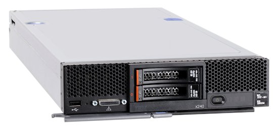
Figure 1. The Flex System x240 Compute Node
Did you know?
Flex System is a new category of computing that integrates multiple server architectures, networking, storage, and system management capability into a single system that is easy to deploy and manage. Flex System has full built-in virtualization support of servers, storage, and networking to speed provisioning and increased resiliency. In addition, it supports open industry standards, such as operating systems, networking and storage fabrics, virtualization, and system management protocols, to easily fit within existing and future data center environments. Flex System is scalable and extendable with multi-generation upgrades to protect and maximize IT investments.
Key features
The Flex System x240 Compute Node is a high-availability, scalable compute node optimized to support the next-generation microprocessor technology and is ideally suited for medium and large businesses. This section describes the key features of the server.
Scalability and performance
The x240 offers numerous features to boost performance, improve scalability, and reduce costs:
- Improves productivity by offering superior system performance with 12-core processors (up to 2.7 GHz core speeds), 10-core processors (up to 3.0 GHz core speeds), 8-core processors (up to 3.3 GHz core speeds), 6-core and 4-core processors (up to 3.5 GHz core speeds), up to 30 MB of L3 cache, and up to two 8 GT/s QPI interconnect links.
- Supports up to two processors, 24 cores, and 48 threads to maximize the concurrent execution of multithreaded applications.
- Supports up to 1866 MHz memory speeds.
- Up to 24 DIMM sockets for maximum scalability and performance.
- Supports up to 768 GB memory with 24x 32 GB LRDIMMs.
- Intelligent and adaptive system performance with Intel Turbo Boost Technology 2.0 allows CPU cores to run at maximum speeds during peak workloads by temporarily going beyond processor TDP.
- Intel Hyper-Threading Technology boosts performance for multi-threaded applications by enabling simultaneous multi-threading within each processor core, up to two threads per core.
- Intel Virtualization Technology integrates hardware-level virtualization hooks that allow operating system vendors to better utilize the hardware for virtualization workloads.
- Intel Advanced Vector Extensions (AVX) significantly improve floating point performance for compute-intensive technical and scientific applications compared with Intel Xeon 5600 series processors.
- The theoretical maximum memory bandwidth of the Intel Xeon processor E5 family is 51.6 GBps, which is 60% more than in the previous generation of Intel Xeon processors.
- The use of solid-state drives (SSDs) instead of or along with traditional spinning drives (HDDs) can significantly improve I/O performance. An SSD can support up to 100 times more I/O operations per second (IOPS) than a typical HDD.
- Supports the Storage Expansion Node providing an additional 12 hot-swap 2.5-inch drive bays for local storage.
- Up to 32 virtual I/O ports per compute node with integrated 10 Gb Ethernet ports, offering the choice of Ethernet, iSCSI, or Fibre Channel over Ethernet (FCoE) connectivity.
- The x240 offers PCI Express 3.0 I/O expansion capabilities that improve the theoretical maximum bandwidth by 60% (8 GT/s per link), compared with the previous generation of PCI Express 2.0.
- With Intel Integrated I/O Technology, the PCI Express 3.0 controller is integrated into the Intel Xeon processor E5 family. This helps to dramatically reduce I/O latency and increase overall system performance.
- Support for high-bandwidth I/O adapters, up to two in each x240 Compute Node. Support for 10 Gb Ethernet, 16 Gb Fibre Channel, and FDR InfiniBand.
- Supports the PCIe Expansion Node for support for up to six additional I/O adapters.
Availability and serviceability
The x240 provides many features to simplify serviceability and increase system uptime:
- Chipkill, memory mirroring and memory rank sparing for redundancy in the event of a non-correctable memory failure.
- Tool-less cover removal provides easy access to upgrades and serviceable parts, such as CPU, memory, and adapter cards.
- Hot-swap drives supporting integrated RAID 1 redundancy for data protection and greater system uptime.
- A light path diagnostics panel and individual light path LEDs to quickly lead the technician to failed (or failing) components. This simplifies servicing, speeds up problem resolution, and helps improve system availability.
- Predictive Failure Analysis (PFA), which detects when system components (such as processors, memory, and hard disk drives) operate outside of standard thresholds and generates pro-active alerts in advance of possible failure, therefore increasing uptime.
- Solid-state drives (SSDs), which offer significantly better reliability than traditional mechanical HDDs for greater uptime.
- Built-in Integrated Management Module II (IMM2) continuously monitors system parameters, triggers alerts, and performs recovering actions in case of failures to minimize downtime.
- Built-in diagnostics using Dynamic Systems Analysis (DSA) Preboot speeds up troubleshooting tasks to reduce service time.
- Three-year customer replaceable unit and onsite limited warranty, next business day 9x5. Optional service upgrades are available.
Manageability and security
Powerful systems management features simplify local and remote management of the x240:
- The x240 includes an Integrated Management Module II (IMM2) to monitor server availability and perform remote management.
- Integrated industry-standard Unified Extensible Firmware Interface (UEFI) enables improved setup, configuration, and updates, and simplifies error handling.
- Integrated Trusted Platform Module (TPM) 1.2 support enables advanced cryptographic functionality, such as digital signatures and remote attestation.
- Industry-standard AES NI support for faster, stronger encryption.
- Integrates with the IBM® Flex System™ Manager for proactive systems management. It offers comprehensive systems management for the entire Flex System platform that help to increase up-time, reduce costs, and improve productivity through advanced server management capabilities.
- Fabric Manager simplifies deployment of infrastructure connections by managing network and storage address assignments.
- Intel Execute Disable Bit functionality can help prevent certain classes of malicious buffer overflow attacks when combined with a supporting operating system.
- Intel Trusted Execution Technology provides enhanced security through hardware-based resistance to malicious software attacks, allowing an application to run in its own isolated space protected from all other software running on a system.
Energy efficiency
The x240 offers the following energy-efficiency features to save energy, reduce operational costs, increase energy availability, and contribute to the green environment:
- Component-sharing design of the Flex System chassis provides ultimate power and cooling savings.
- The Intel Xeon processor E5-2600 v2 product family offers significantly better performance over the E5-2600 family while fitting into the same thermal design power (TDP) limits.
- Intel Intelligent Power Capability powers individual processor elements on and off as needed, to reduce power draw.
- Low-voltage Intel Xeon processors draw less energy to satisfy demands of power and thermally constrained data centers and telecommunication environments.
- Low-voltage 1.35 V DDR3 memory RDIMMs consume 15% less energy than 1.5 V DDR3 RDIMMs.
- Solid state drives (SSDs) consume as much as 80% less power than traditional spinning 2.5-inch HDDs.
- The x240 uses hexagonal ventilation holes, a part of Calibrated Vectored Cooling™ technology. Hexagonal holes can be grouped more densely than round holes, providing more efficient airflow through the system.
Locations of key components and connectors
Figure 2 shows the front of the server.
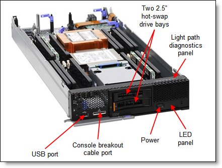
Figure 2. Front view of the Flex System x240 Compute Node
Figure 3 shows the locations of key components inside the server.
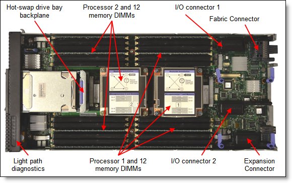
Figure 3. Inside view of the Flex System x240 Compute Node
Standard specifications
The following table lists the standard specifications.
| Components | Specification |
|---|---|
| Models | 8737-x2x, 8737-x4x, and 8737-xMx (x-config). 8737-15X (e-config). |
| Form factor | Standard-width compute node. |
| Chassis support | Flex System Enterprise Chassis. |
| Processor | Up to two Intel Xeon processor E5-2600 v2 product family CPUs with 12 cores (up to 2.7 GHz) or ten cores (up to 3.0 GHz) or eight cores (up to 3.3 GHz) or six cores (up to 3.5 GHz) or four cores (up to 3.5 GHz). Two QPI links up to 8.0 GT/s each. Up to 1866 MHz memory speed. Up to 30 MB L3 cache. |
| Chipset | Intel C600 series. |
| Memory | Up to 24 DIMM sockets (12 DIMMs per processor) using Low Profile (LP) DDR3 DIMMs. RDIMMs, UDIMMs, and LRDIMMs supported. 1.5V and low-voltage 1.35V DIMMs supported. Support for up to 1600 MHz memory speed depending on the processor. Four memory channels per processor (3 DIMMs per channel). |
| Memory maximums | With LRDIMMs: Up to 768 GB with 24x 32 GB LRDIMMs and two processors. With RDIMMs: Up to 384 GB with 24x 16 GB RDIMMs and two processors. With UDIMMs: Up to 64 GB with 16x 4 GB UDIMMs and two processors. |
| Memory protection | Error correction code (ECC), Chipkill (for x4-based memory DIMMs), memory mirroring, and memory rank sparing. |
| Disk drive bays | Two 2.5" hot-swap SAS/SATA drive bays supporting SAS, SATA, and SSD drives. Optional support for up to eight 1.8” SSDs. Up to 12 additional 2.5-inch drive bays with the optional Storage Expansion Node. |
| Maximum internal storage | With two 2.5” hot-swap drives: Up to 2 TB with 1 TB 2.5" NL SAS HDDs, or up to 2.4 TB with 1.2 TB 2.5" SAS HDDs, or up to 2 TB with 1 TB 2.5" SATA HDDs, or up to 3.2 TB with 1.6 TB 2.5" SATA SSDs. An intermix of SAS and SATA HDDs and SSDs is supported. Alternatively, with 1.8” SSDs and ServeRAID M5115 RAID adapter, up to 6.4 TB with eight 800 GB 1.8” SSDs. Additional storage available with an attached Flex System Storage Expansion Node. |
| RAID support | RAID 0 and 1 with integrated LSI SAS2004 controller. Optional ServeRAID M5115 RAID controller with RAID 0, 1, 10, 5, and 50 support and 1 GB cache. Supports up to eight 1.8” SSDs with expansion kits. Optional flash-backup for cache, RAID 6/60, SSD performance enabler. |
| Optical and tape bays | No internal bays; use an external USB drive. See http://support.lenovo.com/en/documents/pd011281 for options. |
| Network interfaces | x4x models: Two 10 Gb Ethernet ports with Embedded 10Gb Virtual Fabric Ethernet LAN-on-motherboard (LOM) controller; Emulex BE3R based; FCoE/iSCSI support with Features on Demand (FoD) upgrade. xMx models: CN4022 2-port 10Gb Converged Adapter standard; Broadcom BCM57840 based; FCoE/iSCSI support standard. x2x models: None standard; optional 1Gb or 10GbE adapters. |
| PCI Expansion slots | Two I/O connectors for adapters. PCI Express 3.0 x16 interface. Includes an Expansion Connector (PCIe 3.0 x16) to connect an expansion node, such as the PCIe Expansion Node. PCIe Expansion Node supports two full-height PCIe adapters, two low-profile PCIe adapters, and two Flex System I/O adapters. |
| Ports | USB ports: One external. Two internal for embedded hypervisor with optional USB Enablement Kit. Console breakout cable port providing local KVM and serial ports (cable standard with chassis; additional cables optional). |
| Systems management | UEFI, Integrated Management Module 2 (IMM2) with Renesas SH7757 controller, Predictive Failure Analysis, light path diagnostics panel, automatic server restart, remote presence. Support for Lenovo XClarity Administrator, Flex System Manager, IBM Systems Director and Active Energy Manager, and Lenovo ServerGuide. |
| Security features | Power-on password, administrator's password, Trusted Platform Module 1.2. |
| Video | Matrox G200eR2 video core with 16 MB video memory integrated into the IMM2. Maximum resolution is 1600x1200 at 75 Hz with 16 M colors. |
| Limited warranty | Three-year customer-replaceable unit and onsite limited warranty with 9x5/NBD. |
| Operating systems supported | Microsoft Windows Server, Red Hat Enterprise Linux, SUSE Linux Enterprise Server, VMware ESXi. See the Operating system support section for specifics. |
| Service and support | Optional service upgrades are available through ServicePacs®: 4-hour or 2-hour response time, 8-hour fix time, 1-year or 2-year warranty extension, remote technical support for hardware and selected and original equipment manufacturer (OEM) software. |
| Dimensions | Width: 215 mm (8.5”), height 51 mm (2.0”), depth 493 mm (19.4”). |
| Weight | Maximum configuration: 6.98 kg (15.4 lb). |
The x240 servers are shipped with the following items:
- Statement of Limited Warranty
- Important Notices
- Documentation CD that contains the Installation and User's Guide
Standard models
Table 2 lists the standard models.
| Model | Intel Xeon Processor (2 maximum)* |
Memory | Disk adapter |
Disk bays† | Disks | 10 GbE‡ | I/O slots |
| Models with embedded 10 Gb Virtual Fabric Ethernet | |||||||
| 8737-14x | 1x E5-2609 v2 4C 2.5GHz 10MB 1333MHz 80W |
1x 8 GB (1333 MHz) |
LSI SAS2004 | 2x 2.5-inch hot-swap |
Open | 10 GbE Embedded |
1 used / 2 max |
| 8737-24x | 1x E5-2620 v2 6C 2.1GHz 15MB 1600MHz 80W |
1x 8 GB 1600 MHz |
LSI SAS2004 | 2x 2.5-inch hot-swap |
Open | 10 GbE Embedded |
1 used / 2 max |
| 8737-B4x | 1x E5-2630 v2 6C 2.6GHz 15MB 1600MHz 80W |
1x 8 GB 1600 MHz |
LSI SAS2004 | 2x 2.5-inch hot-swap |
Open | 10 GbE Embedded |
1 used / 2 max |
| 8737-34x | 1x E5-2640 v2 8C 2.0GHz 20MB 1600MHz 95W |
1x 8 GB 1600 MHz |
LSI SAS2004 | 2x 2.5-inch hot-swap |
Open | 10 GbE Embedded |
1 used / 2 max |
| 8737-44x | 1x E5-2650 v2 8C 2.6GHz 20MB 1866MHz 95W |
1x 8 GB 1866 MHz |
LSI SAS2004 | 2x 2.5-inch hot-swap |
Open | 10 GbE Embedded |
1 used / 2 max |
| 8737-C4x | 1x E5-2650L v2 10C 1.7GHz 25MB 1600MHz 70W |
1x 8 GB 1600 MHz |
LSI SAS2004 | 2x 2.5-inch hot-swap |
Open | 10 GbE Embedded |
1 used / 2 max |
| 8737-54x | 1x E5-2660 v2 10C 2.2GHz 25MB 1866MHz 95W |
1x 8 GB 1866 MHz |
LSI SAS2004 | 2x 2.5-inch hot-swap |
Open | 10 GbE Embedded |
1 used / 2 max |
| 8737-64x | 1x E5-2670 v2 10C 2.5GHz 25MB 1866MHz 115W |
1x 8 GB 1866 MHz |
LSI SAS2004 | 2x 2.5-inch hot-swap |
Open | 10 GbE Embedded |
1 used / 2 max |
| 8737-74x | 1x E5-2680 v2 10C 2.8GHz 25MB 1866MHz 115W |
1x 8 GB 1866 MHz |
LSI SAS2004 | 2x 2.5-inch hot-swap |
Open | 10 GbE Embedded |
1 used / 2 max |
| 8737-84x | 1x E5-2690 v2 10C 3.0GHz 25MB 1866MHz 130W |
1x 8 GB 1866 MHz |
LSI SAS2004 | 2x 2.5-inch hot-swap |
Open | 10 GbE Embedded |
1 used / 2 max |
| 8737-8Dx | 2x E5-2690 v2 10C 3.0GHz 25MB 1866MHz 130W |
16x 16 GB 1866 MHz |
LSI SAS2004 | 2x 2.5-inch hot-swap |
Open§ | 10 GbE Embedded |
1 used / 2 max |
| 8737-94x | 1x E5-2697 v2 12C 2.7GHz 30MB 1866MHz 130W |
1x 8 GB 1866 MHz |
LSI SAS2004 | 2x 2.5-inch hot-swap |
Open | 10 GbE Embedded |
1 used / 2 max |
| Models with Flex System CN4022 2-port 10Gb Converged Adapter | |||||||
| 8737-1Mx | 1x E5-2609 v2 4C 2.5GHz 10MB 1333MHz 80W |
1x 8 GB (1333 MHz) |
LSI SAS2004 | 2x 2.5-inch hot-swap |
Open | CN4022 Adapter |
1 used / 2 max |
| 8737-2Mx | 1x E5-2620 v2 6C 2.1GHz 15MB 1600MHz 80W |
1x 8 GB 1600 MHz |
LSI SAS2004 | 2x 2.5-inch hot-swap |
Open | CN4022 Adapter |
1 used / 2 max |
| 8737-BMx | 1x E5-2630 v2 6C 2.6GHz 15MB 1600MHz 80W |
1x 8 GB 1600 MHz |
LSI SAS2004 | 2x 2.5-inch hot-swap |
Open | CN4022 Adapter |
1 used / 2 max |
| 8737-3Mx | 1x E5-2640 v2 8C 2.0GHz 20MB 1600MHz 95W |
1x 8 GB 1600 MHz |
LSI SAS2004 | 2x 2.5-inch hot-swap |
Open | CN4022 Adapter |
1 used / 2 max |
| 8737-4Mx | 1x E5-2650 v2 8C 2.6GHz 20MB 1866MHz 95W |
1x 8 GB 1866 MHz |
LSI SAS2004 | 2x 2.5-inch hot-swap |
Open | CN4022 Adapter |
1 used / 2 max |
| 8737-CMx | 1x E5-2650L v2 10C 1.7GHz 25MB 1600MHz 70W |
1x 8 GB 1600 MHz |
LSI SAS2004 | 2x 2.5-inch hot-swap |
Open | CN4022 Adapter |
1 used / 2 max |
| 8737-5Mx | 1x E5-2660 v2 10C 2.2GHz 25MB 1866MHz 95W |
1x 8 GB 1866 MHz |
LSI SAS2004 | 2x 2.5-inch hot-swap |
Open | CN4022 Adapter |
1 used / 2 max |
| 8737-6Mx | 1x E5-2670 v2 10C 2.5GHz 25MB 1866MHz 115W |
1x 8 GB 1866 MHz |
LSI SAS2004 | 2x 2.5-inch hot-swap |
Open | CN4022 Adapter |
1 used / 2 max |
| 8737-7Mx | 1x E5-2680 v2 10C 2.8GHz 25MB 1866MHz 115W |
1x 8 GB 1866 MHz |
LSI SAS2004 | 2x 2.5-inch hot-swap |
Open | CN4022 Adapter |
1 used / 2 max |
| 8737-8Mx | 1x E5-2690 v2 10C 3.0GHz 25MB 1866MHz 130W |
1x 8 GB 1866 MHz |
LSI SAS2004 | 2x 2.5-inch hot-swap |
Open | CN4022 Adapter |
1 used / 2 max |
| 8737-9Mx | 1x E5-2697 v2 12C 2.7GHz 30MB 1866MHz 130W |
1x 8 GB 1866 MHz |
LSI SAS2004 | 2x 2.5-inch hot-swap |
Open | CN4022 Adapter |
1 used / 2 max |
| Models without networking standard | |||||||
| 8737-22x | 1x E5-2620 v2 6C 2.1GHz 15MB 1600MHz 80W |
1x 8 GB 1600 MHz |
LSI SAS2004 | 2x 2.5-inch hot-swap |
Open | Optional | 0 used / 2 max |
| 8737-42x | 1x E5-2650 v2 8C 2.6GHz 20MB 1866MHz 95W |
1x 8 GB 1866 MHz |
LSI SAS2004 | 2x 2.5-inch hot-swap |
Open | Optional | 0 used / 2 max |
| 8737-62x | 1x E5-2670 v2 10C 2.5GHz 25MB 1866MHz 115W |
1x 8 GB 1866 MHz |
LSI SAS2004 | 2x 2.5-inch hot-swap |
Open | Optional | 0 used / 2 max |
| 8737-72x | 1x E5-2680 v2 10C 2.8GHz 25MB 1866MHz 115W |
1x 8 GB 1866 MHz |
LSI SAS2004 | 2x 2.5-inch hot-swap |
Open | Optional | 0 used / 2 max |
* Processor detail: Processor quantity, model, cores, core speed, L3 cache, memory speed, power TDP rating.
† The 2.5-inch drive bays can be replaced and expanded with 1.8" solid-state drive bays and a ServeRAID M5115 RAID controller to support up to eight 1.8-inch SSDs.
‡ Models have the following Ethernet controllers standard:
- The x4x models include an Embedded 10Gb Virtual Fabric Ethernet controller; connections are routed using a Fabric Connector. The Fabric Connector precludes the use of an I/O adapter in I/O connector 1.
- The xMx models include a Flex System CN4022 2-port 10Gb Converged Adapter in slot 1.
§ Model 8Dx includes 1x Flex System x240 USB Enablement Kit, 1x USB Memory Key for VMware ESXi 5.1, and 1x Blank USB Memory Key for VMware ESXi Downloads.
TopSeller models
The following table lists the available TopSeller models.
Table 3. TopSeller models
| Model | Intel Xeon Processor (2 maximum)* |
Memory | Disk adapter |
Disk bays† | Disks | 10 GbE | I/O slots |
| TopSeller models - North America | |||||||
| 8737-E1x | 2x E5-2620 v2 6C 2.1GHz 15MB 1600MHz 80W |
2x 16 GB 1600 MHz |
LSI SAS3004 | 2.5” hot-swap (0 / 2) | Open | 2x 10 Gb + FCoE‡ |
1 / 2 |
| 8737-E2x | 2x E5-2640 v2 8C 2.0GHz 20MB 1600MHz 95W |
4x 16 GB 1600 MHz |
LSI SAS3004 | 2.5” hot-swap (0 / 2) | Open | 2x 10 Gb + FCoE‡ |
1 / 2 |
| 8737-E3x | 2x E5-2660 v2 10C 2.2GHz 25MB 1866MHz 95W |
4x 16 GB 1600 MHz |
LSI SAS3004 | 2.5” hot-swap (0 / 2) | Open | 2x 10 Gb + FCoE‡ |
1 / 2 |
| 8737-E4x | 2x E5-2680 v2 10C 2.8GHz 25MB 1866MHz 115W |
8x 16 GB 1600 MHz |
LSI SAS3004 | 2.5” hot-swap (0 / 2) | Open | 2x 10 Gb + FCoE‡ |
1 / 2 |
* Processor detail: Processor quantity, model, cores, core speed, L3 cache, memory speed, power TDP rating.
† The 2.5-inch drive bays can be replaced and expanded with 1.8" solid-state drive bays and a ServeRAID M5115 RAID controller to support up to eight 1.8-inch SSDs.
‡ These models have an onboard 10 GbE controller with two 10 GbE ports plus Virtual Fabric Advanced Software Upgrade (LOM) to enable iSCSI and FCoE
Chassis support
The x240 is supported in the Flex System chassis in the following table.
| Compute node |
Enterprise Chassis with CMM 68Y7030 |
Enterprise Chassis with CMM2 00FJ669 |
Carrier-Grade Chassis |
|---|---|---|---|
| x240 (8737) | Yes | Yes | No |
Up to 14 x240 Compute Nodes can be installed in the chassis, however, the actual number that can be installed in a chassis depends on these factors:
- The TDP power rating for the processors that are installed in the x240
- The number of power supplies installed in the chassis
- The capacity of the power supplies installed (2100 W or 2500 W)
- The chassis power redundancy policy used (N+1 or N+N)
The following table provides guidelines about what number of x240 Compute Nodes can be installed. For more guidance, use the Power Configurator, found at the following website:
https://support.lenovo.com/us/en/documents/LNVO-PWRCONF
In the table:
- Green = No restriction to the number of x240 Compute Nodes that are installable
- Yellow = Some bays must be left empty in the chassis
Table 4. Maximum number of x240 Compute Nodes installable based on power supplies installed and power redundancy policy used
| x240 TDP rating |
2100 W power supplies installed
|
2500 W power supplies installed
|
||||||
| N+1, N=5 6 power supplies |
N+1, N=4 5 power supplies |
N+1, N=3 5 power supplies |
N+N, N=3 6 power supplies |
N+1, N=5 6 power supplies |
N+1, N=4 5 power supplies |
N+1, N=3 4 power supplies |
N+N, N=3 6 power supplies |
|
| 60 W | 14 | 14 | 14 | 14 | 14 | 14 | 14 | 14 |
| 70 W | 14 | 14 | 13 | 14 | 14 | 14 | 14 | 14 |
| 80 W | 14 | 14 | 13 | 13 | 14 | 14 | 14 | 14 |
| 95 W | 14 | 14 | 12 | 12 | 14 | 14 | 14 | 14 |
| 115 W | 14 | 14 | 11 | 12 | 14 | 14 | 14 | 14 |
| 130 W | 14 | 14 | 11 | 11 | 14 | 14 | 13 | 14 |
| 135 W | 14 | 14 | 10 | 11 | 14 | 14 | 13 | 14 |
Processor options
The x240 supports the processor options listed in the following table. The server supports one or two processors. The table also shows which server models have each processor standard, if any.
Table 5. Processor options
| Part number |
Feature code* | Intel Xeon processor description | Models where used |
| 00Y2850 | A4P9 / A4PW | Intel Xeon E5-2603 v2 4C 1.8GHz 10MB 1333MHz 80W | - |
| 00Y2851 | A4PA / A4PX | Intel Xeon E5-2609 v2 4C 2.5GHz 10MB 1333MHz 80W | 14x, 1Mx |
| 00AE510 | A4PQ / A4QB | Intel Xeon E5-2618L v2 6C 2.0GHz 15MB 1333MHz 50W (EMB) | - |
| 00Y2852 | A4PB / A4PY | Intel Xeon E5-2620 v2 6C 2.1GHz 15MB 1600MHz 80W | 24x, 2Mx, 22x |
| 00AE513 | A4PT / A4QE | Intel Xeon E5-2628L v2 8C 2.2GHz 20MB 1600MHz 70W (EMB) | - |
| 00Y2853 | A4PC / A4PZ | Intel Xeon E5-2630 v2 6C 2.6GHz 15MB 1600MHz 80W | B4x, BMx |
| 00Y2864 | A4PN / A4Q9 | Intel Xeon E5-2630L v2 6C 2.4GHz 15MB 1600MHz 60W | - |
| 00Y2861 | A4PK / A4Q6 | Intel Xeon E5-2637 v2 4C 3.5GHz 15MB 1866MHZ 130W | - |
| 00Y2854 | A4PD / A4Q0 | Intel Xeon E5-2640 v2 8C 2.0GHz 20MB 1600MHz 95W | 34x, 3Mx |
| 00Y2862 | A4PL / A4Q7 | Intel Xeon E5-2643 v2 6C 3.5GHz 25MB 1866MHz 130W | - |
| 00AE511 | A4PR / A4QC | Intel Xeon E5-2648L v2 10C 2.0GHz 25MB 1866MHz 70W (EMB) | - |
| 00Y2855 | A4PP / A4Q1 | Intel Xeon E5-2650 v2 8C 2.6GHz 20MB 1866MHz 95W | 44x, 4Mx, 42x |
| 00Y2865 | A4PE / A4QA | Intel Xeon E5-2650L v2 10C 1.7GHz 25MB 1600MHz 70W | C4x, CMx |
| 00AE512 | A4PS / A4QD | Intel Xeon E5-2658 v2 10C 2.4GHz 25MB 1866MHz 95W (EMB) | - |
| 00Y2856 | A4PF / A4Q2 | Intel Xeon E5-2660 v2 10C 2.2GHz 25MB 1866MHz 95W | 54x, 5Mx |
| 00Y2863 | A4PM / A4Q8 | Intel Xeon E5-2667 v2 8C 3.3GHz 25MB 1866MHz 130W** | - |
| 00Y2857 | A4PG / A4Q3 | Intel Xeon E5-2670 v2 10C 2.5GHz 25MB 1866MHz 115W | 64x, 6Mx, 62x |
| 00Y2858 | A4PH / A4Q4 | Intel Xeon E5-2680 v2 10C 2.8GHz 25MB 1866MHz 115W | 74x, 7Mx, 72x |
| 00Y2859 | A4PJ / A4Q5 | Intel Xeon E5-2690 v2 10C 3.0GHz 25MB 1866MHz 130W | 84x, 8Dx, 8Mx |
| 00Y2848 | A4P7 / A4PU | Intel Xeon E5-2695 v2 12C 2.4GHz 30MB 1866MHz 115W | - |
| 00Y2849 | A4P8 / A4PV | Intel Xeon E5-2697 v2 12C 2.7GHz 30MB 1866MHz 130W | 94x, 9Mx |
* The first feature code is for processor 1 and second feature code is for processor 2.
** Use of the Intel Xeon E5-2667 v2 processor in the Flex System x240 Compute Node is limited to 30 °C up to 3000 feet (914 m). Above 3000 feet, a de-rating of 1 °C for every 600 feet (182 m) should be applied. Use of the ServeRAID M5115 SAS/SATA RAID Controller with the E5-2667 v2 processor is not supported. Flex System configurations using the E5-2667 v2 processor will operate at acoustic levels significantly greater than typical Flex System levels, and the following noise hazard warning may apply: "Notice: Government regulations (such as those prescribed by OSHA or European Community Directives) may govern noise level exposure in the workplace and may apply to you and your server installation. The actual sound pressure levels in your installation depend upon a variety of factors, including the number of racks in the installation; the size, materials, and configuration of the room; the noise levels from other equipment; the room ambient temperature, and employees’ location in relation to the equipment. Further, compliance with such government regulations also depends upon a variety of additional factors, including the duration of employees’ exposure and whether employees wear hearing protection. Lenovo recommends that you consult with qualified experts in this field to determine whether you are in compliance with the applicable regulations."
Memory options
DDR3 memory is compatibility tested and tuned for optimal performance and throughput. Memory specifications are integrated into the light path diagnostics for immediate system performance feedback and optimum system uptime. From a service and support standpoint, memory automatically assumes the system warranty, and Lenovo provides service and support worldwide.
The following table lists memory options available for the x240 compute node with E5-2600 v2 processors. DIMMs can be installed one at a time, but for performance reasons, install them in sets of four (one for each of the four memory channels).
Table 6. Memory options for the x240 with E5-2600 v2 processors
| Part number | Feature code |
Description | Models where used |
| Registered DIMMs (RDIMMs) - 1866 MHz | |||
| 00D5048 | A3QL | 16GB (1x16GB, 2Rx4, 1.5V) PC3-14900 CL13 ECC DDR3 1866MHz LP RDIMM | 8Dx |
| 00D5028 | A3QF | 4GB (1x4GB, 2Rx8, 1.5V) PC3-14900 CL13 ECC DDR3 1866MHz LP RDIMM | - |
| Registered DIMMs (RDIMMs) - 1600 MHz | |||
| 46W0672 | A3QM | 16GB (1x16GB, 2Rx4, 1.35V) PC3L-12800 CL11 ECC DDR3 1600MHz LP RDIMM | - |
| 00D5036 | A3QH | 8GB (1x8GB, 1Rx4, 1.35V) PC3L-12800 CL11 ECC DDR3 1600MHz LP RDIMM | All 1600 MHz models |
| 00D5024 | A3QE | 4GB (1x4GB, 1Rx4, 1.35V) PC3L-12800 CL11 ECC DDR3 1600MHz LP RDIMM | - |
| Unbuffered DIMMs (UDIMMs) | |||
| 00D5016 | A3QC | 8GB (1x8GB, 2Rx8, 1.35V) PC3L-12800 CL11 ECC DDR3 1600MHz LP UDIMM | - |
| 00D5012 | A3QB | 4GB (1x4GB, 2Rx8, 1.35V) PC3L-12800 CL11 ECC DDR3 1600MHz LP UDIMM | - |
| Load-reduced DIMMs (LRDIMMs) | |||
| 46W0761 | A47K | 32GB (1x32GB, 4Rx4, 1.5V) PC3-14900 CL13 ECC DDR3 1866MHz LP LRDIMM | - |
The x240 supports Low Profile (LP) DDR3 memory RDIMMs, UDIMMs, and LRDIMMs. The server supports up to 12 DIMMs when one processor is installed and up to 24 DIMMs when two processors are installed. Each processor has four memory channels, and there are three DIMMs per channel.
The following rules apply when selecting the memory configuration:
- Mixing 1.5 V and 1.35 V DIMMs in the same server is supported. In such a case all DIMMs operate at 1.5 V.
- Mixing of different types of DIMMs (UDIMM , RDIMM and LRDIMM) in the same server is not supported.
- The maximum number of ranks supported per channel is eight.
- The maximum quantity of DIMMs that can be installed in the server depends on the number of CPUs, DIMM rank, and operating voltage, as shown in the "Max. qty supported" row in the following table. The shaded cells indicate that the DIMM type supports the maximum number of DIMMs (24 for the x240)
- All DIMMs in all CPU memory channels operate at the same speed, which is determined as the lowest value of:
- Memory speed supported by specific CPU
- Lowest maximum operating speed for the selected memory configuration that depends on rated speed, as shown under the "Max. operating speed" section in the following table. The shaded cells indicate that the speed indicated is the maximum that the DIMM allows.
The following two tables (Part 1 and Part 2) show the maximum memory speeds that are achievable based on the installed DIMMs and the number of DIMMs per channel. The tables also show maximum memory capacity at any speed supported by the DIMM and maximum memory capacity at rated DIMM speed. In the tables, cells highlighted with a gray background indicate when the specific combination of DIMM voltage and number of DIMMs per channel still allows the DIMMs to operate at rated speed.
Table 7. Maximum memory speeds (Part 1 - UDIMMs and LRDIMMs)
| Specification |
UDIMMs
|
LRDIMMs
|
|
| Rank | Dual rank | Quad rank | |
| Part numbers | 00D5012 (4 GB) 00D5016 (8 GB) |
46W0761 (32 GB) | |
| Rated speed | 1600 MHz | 1866 MHz | |
| Rated voltage | 1.35 V | 1.5 V | |
| Operating voltage | 1.35 V | 1.5 V | 1.5 V |
| Maximum quantity* | 16 | 16 | 24 |
| Largest DIMM | 8 GB | 8 GB | 32 GB |
| Max memory capacity | 128 GB | 128 GB | 768 GB |
| Max memory at rated speed | None | 128 GB | 512 GB |
| Maximum operating speed (MHz) | |||
| One DIMM per channel | 1333 MHz | 1600 MHz | 1866 MHz |
| Two DIMMs per channel | 1333 MHz | 1600 MHz | 1866 MHz |
| Three DIMMs per channel | NS† | NS† | 1333 MHz |
* The maximum quantity supported is shown for two processors installed. When one processor is installed, the maximum quantity supported is half of that shown.
† NS = Not supported. UDIMMs only support up to 2 DIMMs per channel.
Table 8. Maximum memory speeds (Part 2 - Single-rank and dual-rank RDIMMs)
| Specification |
RDIMMs
|
||||
| Rank | Single rank | Dual rank | |||
| Part numbers | 00D5024 (4 GB) 00D5036 (8 GB) |
00D5044 (8 GB) 46W0672 (16 GB) |
00D5028 (4 GB) 00D5040 (8 GB) 00D5048 (16 GB) |
||
| Rated speed | 1600 MHz | 1600 MHz | 1866 MHz | ||
| Rated voltage | 1.35 V | 1.35 V | 1.5 V | ||
| Operating voltage | 1.35 V | 1.5 V | 1.35 V | 1.5 V | 1.5 V |
| Max quantity† | 24 | 24 | 24 | 24 | 24 |
| Largest DIMM | 8 GB | 8 GB | 16 GB | 16 GB | 16 GB |
| Max memory capacity | 192 GB | 192 GB | 384 GB | 384 GB | 384 GB |
| Max memory at rated speed | None | 128 GB | None | 256 GB | 256 GB |
| Maximum operating speed (MHz) | |||||
| One DIMM per channel | 1333 MHz | 1600 MHz | 1333 MHz | 1600 MHz | 1866 MHz |
| Two DIMMs per channel | 1333 MHz | 1600 MHz | 1333 MHz | 1600 MHz | 1866 MHz |
| Three DIMMs per channel | 1066 MHz | 1066 MHz | 1066 MHz | 1333 MHz / 1066 MHz* |
1333 MHz / 1066 MHz** |
† The maximum quantity that is supported is shown for two processors installed. When one processor is installed, the maximum quantity that is supported is half of that shown.
* 00D5044 (8 GB) operates at 1066 MHz at three DIMMs per channel; 46W0672 (16 GB) operates at 1333 MHz at three DIMMs per channel
** 00D5028 (4 GB) and 00D5040 (8 GB) operate at 1066 MHz at three DIMMs per channel; 00D5048 (16 GB) operates at 1333 MHz at three DIMMs per channel
The following memory protection technologies are supported:
- ECC
- Chipkill (for x4-based memory DIMMs -- look for "x4" in the DIMM description)
- Memory mirroring
- Memory sparing
If memory mirroring is used, then DIMMs must be installed in pairs (minimum of one pair per CPU), and both DIMMs in a pair must be identical in type and size.
If memory rank sparing is used, then a minimum of one quad-rank DIMM or two single-rank or dual-rank DIMMs must be installed per populated channel (the DIMMs do not need being identical). In rank sparing mode, one rank of a DIMM in each populated channel is reserved as spare memory. The size of a rank varies depending on the DIMMs installed.
Internal storage
The x240 server has two 2.5-inch hot-swap drive bays accessible from the front of the blade server (Figure 2). These bays connect to the integrated LSI SAS2004 6 Gbps SAS/SATA RAID-on-Chip (ROC) controller.
The integrated LSI SAS2004 ROC has the following features:
- Four-port LSI SAS2004 controller with 6 Gbps throughput per port
- PCIe x4 Gen 2 host interface
- Two SAS ports routed internally to the two hot-swap drive bays
- Supports RAID-0, RAID-1 and RAID-1E
The x240 also supports up to eight 1.8-inch drives with the addition of the ServeRAID M5115 controller and additional SSD tray hardware. These are described in the next section.
Supported drives are listed in the Internal drive options section.
ServeRAID M5115 SAS/SATA controller
The x240 supports up to eight 1.8-inch solid-state drives combined with a ServeRAID M5115 SAS/SATA controller (90Y4390). The M5115 attaches to the I/O adapter 1 connector and can be attached even if the Compute Node Fabric Connector is installed (used to route the Embedded 10Gb Virtual Fabric Adapter to bays 1 and 2, as discussed in "I/O expansion options"). The ServeRAID M5115 cannot be installed if an adapter is installed in I/O adapter slot 1.
The ServeRAID M5115 supports combinations of 2.5-inch drives and 1.8-inch solid state drives:
- Up to two 2.5-inch drives only
- Up to four 1.8-inch drives only
- Up to two 2.5-inch drives, plus up to four 1.8-inch solid state drives
- Up to eight 1.8-inch solid state drives
The ServeRAID M5115 SAS/SATA Controller (90Y4390) provides an advanced RAID controller supporting RAID 0, 1, 10, 5, 50, and optional 6 and 60. It includes 1 GB of cache, which can be backed up to Flash when attached to the supercapacitor included with the optional ServeRAID M5100 Series Enablement Kit (90Y4342).
At least one hardware kit is required with the ServeRAID M5115 controller, and there are three hardware kits that are supported that enable specific drive support.
| Part number | Feature code |
Description | Maximum supported |
| 90Y4390 | A2XW | ServeRAID M5115 SAS/SATA Controller for Flex System | 1 |
| 90Y4342 | A2XX | ServeRAID M5100 Series Enablement Kit for Flex System x240 | 1 |
| 47C8808 | A47D | ServeRAID M5100 Series Flex System Flash Kit v2 for x240 | 1 |
| 90Y4391 | A2XZ | ServeRAID M5100 Series SSD Expansion Kit for Flex System x240 | 1 |
The hardware kits have the following features:
- ServeRAID M5100 Series Enablement Kit for Flex System x240 (90Y4342) enables support for up to two 2.5” HDDs or SSDs in the hot-swap bays in the front of the server. It includes a CacheVault unit, which enables MegaRAID CacheVault flash cache protection. This enablement kit replaces the standard two-bay backplane (which is attached via the planar to an onboard controller) with a new backplane that attaches to an included flex cable to the M5115 controller. It also includes an air baffle, which also serves as an attachment for the CacheVault unit.
MegaRAID CacheVault flash cache protection uses NAND flash memory powered by a supercapacitor to protect data stored in the controller cache. This module eliminates the need for a lithium-ion battery commonly used to protect DRAM cache memory on PCI RAID controllers. To avoid the possibility of data loss or corruption during a power or server failure, CacheVault technology transfers the contents of the DRAM cache to NAND flash using power from the supercapacitor. After the power is restored to the RAID controller, the saved data is transferred from the NAND flash back to the DRAM cache, which can then be flushed to disk.
Tip: The Enablement Kit is only required if 2.5-inch drives are to be used. If you plan to install four or eight 1.8-inch SSDs only, then this kit is not required.
- ServeRAID M5100 Series Flex System Flash Kit v2 for x240 (47C8808) enables support for up to four 1.8-inch SSDs. This kit replaces the standard two-bay backplane with a four-bay SSD backplane that attaches to an included flex cable to the M5115 controller. Because only SSDs are supported, a CacheVault unit is not required, and therefore this kit does not have a supercap. This v2 kit provides support for the latest high-performance SSDs.
Note: The original ServeRAID M5100 Series Flex System Flash Kit for x240, 90Y4341 is not supported.
- ServeRAID M5100 Series SSD Expansion Kit for Flex System x240 (90Y4391) enables support for up to four internal 1.8-inch SSDs. This kit includes two air baffles, left and right, which can attach two 1.8-inch SSD attachment locations and Flex cables for attachment to up to four 1.8-inch SSDs.
Note: The SSD Expansion Kit cannot be installed if the USB Enablement Kit, 49Y8119, is already installed as these kits occupy the same location in the server.
The following table shows the kits required for each combination of drives. For example, if you plan to install eight 1.8-inch SSDs, then you will need the M5115 controller, the Flash kit, and the SSD Expansion kit.
Table 10. ServeRAID M5115 hardware kit usage matrix
|
Desired drive support
|
Components required
|
|||||
| Maximum number of 2.5" drives |
Maximum number of 1.8" SSDs |
ServeRAID M5115 90Y4390 |
Enablement Kit 90Y4342 |
Flash Kit v2 47C8808 |
SSD Expansion Kit 90Y4391 |
|
| 2 | 0 |
=>
|
Required | Required | ||
| 0 | 4 (front) |
=>
|
Required | Required | ||
| 2 | 4 (internal) |
=>
|
Required | Required | Required | |
| 0 | 8 (both) |
=>
|
Required | Required | Required | |
The following figure shows how the ServeRAID M5115 and the Enablement Kit are installed in the server to support two 2.5-inch drives with MegaRAID CacheVault flash cache protection (row 1 of the preceding table).
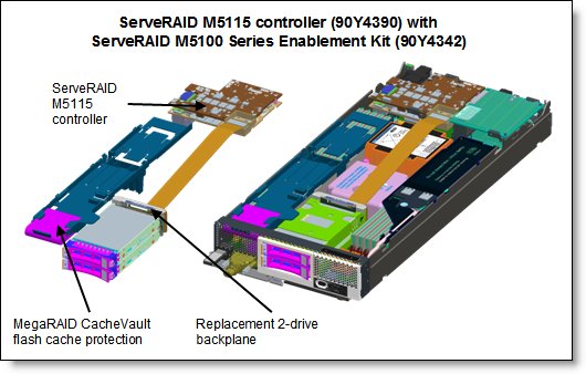
Figure 4. The ServeRAID M5115 and the Enablement Kit installed
The following figure shows how the ServeRAID M5115 and Flash and SSD Expansion Kits are installed in the server to support eight 1.8-inch solid-state drives (row 4 of the preceding table).
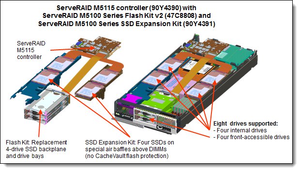
Figure 5. ServeRAID M5115 with Flash and SSD Expansion Kits installed
The eight SSDs are installed in the following locations:
- Four in the front of the system in place of the two 2.5-inch drive bays
- Two in a tray above one of the memory banks for CPU 1
- Two in a tray above one of the memory banks for CPU 2
The ServeRAID M5115 controller has the following specifications:
- Eight internal 6 Gbps SAS/SATA ports
- PCI Express 3.0 x8 host interface
- 6 Gbps throughput per port
- 800 MHz dual-core PowerPC processor with LSI SAS2208 6 Gbps RAID on Chip (ROC) controller
- Support for RAID levels 0, 1, 10, 5, 50 standard; support for RAID 6 and 60 with optional upgrade using 90Y4411
- Onboard 1 GB data cache (DDR3 running at 1333 MHz) with optional flash backup (MegaRAID CacheVault technology) as part of the Enablement Kit 90Y4342.
- Support for SAS and SATA HDDs and SSDs
- Support for intermixing SAS and SATA HDDs and SSDs; mixing different types of drives in the same array (drive group) not recommended
- Support for self-encrypting drives (SEDs) with MegaRAID SafeStore
- Optional support for SSD performance acceleration with MegaRAID FastPath and SSD caching with MegaRAID CacheCade Pro 2.0 (90Y4447)
- Support for up to 64 virtual drives, up to 128 drive groups, up to 16 virtual drives per one drive group, and up to 32 physical drives per one drive group
- Support for logical unit number (LUN) sizes up to 64 TB
- Configurable stripe size up to 1 MB
- Compliant with Disk Data Format (DDF) configuration on disk (COD)
- S.M.A.R.T. support
- MegaRAID Storage Manager management software
Optional add-ons to the ServeRAID M5115 controller are RAID 6 support, SSD performance accelerator, and SSD caching enabler. The feature upgrades are as listed in the following table. These are all FoD license upgrades.
Table 11. Supported upgrade features
| Part number | Feature code |
Description | Maximum supported |
| 90Y4410 | A2Y1 | ServeRAID M5100 Series RAID 6 Upgrade for Flex System | 1 |
| 90Y4412 | A2Y2 | ServeRAID M5100 Series Performance Upgrade for Flex System (MegaRAID FastPath) |
1 |
| 90Y4447 | A36G | ServeRAID M5100 Series SSD Caching Enabler for Flex System (MegaRAID CacheCade Pro 2.0) |
1 |
These features are described as follows:
- RAID 6 Upgrade (90Y4410)
Adds support for RAID 6 and RAID 60. This is a Feature on Demand license.
- Performance Upgrade (90Y4412)
The Performance Upgrade for Flex System (implemented using the LSI MegaRAID FastPath software) provides high-performance I/O acceleration for SSD-based virtual drives by exploiting an extremely low-latency I/O path to increase the maximum I/O per second (IOPS) capability of the controller. This feature boosts the performance of applications with a highly random data storage access pattern, such as transactional databases. Part number 90Y4412 is a Feature on Demand license.
- SSD Caching Enabler for traditional hard drives (90Y4447)
The SSD Caching Enabler for Flex System (implemented using the LSI MegaRAID CacheCade Pro 2.0) is designed to accelerate the performance of hard disk drive (HDD) arrays with only an incremental investment in solid-state drive (SSD) technology. The feature enables the SSDs to be configured as a dedicated cache to help maximize the I/O performance for transaction-intensive applications, such as databases and web serving. The feature tracks data storage access patterns and identifies the most frequently accessed data. The hot data is then automatically stored on the SSDs that are assigned as a dedicated cache pool on the ServeRAID controller. Part number 90Y4447 is a Feature on Demand license. This feature requires at least one SSD drive be installed.
Note: Not all SSDs support SSD Caching Enabler (CacheCade) feature. See http://ibm.com/support/entry/portal/docdisplay?lndocid=MIGR-5094754 for details.
Internal drive options
The 2.5" drive bays support SAS or SATA hard disk drives (HDDs) or SATA solid state drives (SSDs). The following table lists the supported 2.5" drive options.
| Part number | Feature | Description | Maximum supported |
|---|---|---|---|
| 2.5-inch hot-swap HDDs - 6 Gb SAS 10K | |||
| 90Y8877 | A2XC | 300GB 10K 6Gbps SAS 2.5" SFF G2HS HDD | 2 |
| 90Y8872 | A2XD | 600GB 10K 6Gbps SAS 2.5" SFF G2HS HDD | 2 |
| 81Y9650 | A282 | 900GB 10K 6Gbps SAS 2.5" SFF HS HDD | 2 |
| 2.5-inch hot-swap HDDs - 6 Gb SAS 15K | |||
| 81Y9670 | A283 | 300GB 15K 6Gbps SAS 2.5" G2HS HDD | 2 |
| 00AJ300 | A4VB | 600GB 15K 6Gbps SAS 2.5" G2HS HDD | 2 |
| 2.5-inch hot-swap HDDs - 6 Gb NL SAS | |||
| 90Y8953 | A2XE | 500GB 7.2K 6Gbps NL SAS 2.5" SFF G2HS HDD | 2 |
| 81Y9690 | A1P3 | 1TB 7.2K 6Gbps NL SAS 2.5" SFF HS HDD | 2 |
| 2.5-inch hot-swap HDDs - 6 Gb NL SATA | |||
| 81Y9726 | A1NZ | 500GB 7.2K 6Gbps NL SATA 2.5" SFF HS HDD | 2 |
| 81Y9730 | A1AV | 1TB 7.2K 6Gbps NL SATA 2.5" SFF HS HDD | 2 |
| 2.5-inch hot-swap SED HDDs - 6 Gb SAS 10K | |||
| 90Y8913 | A2XF | 300GB 10K 6Gbps SAS 2.5" SFF G2HS SED | 2 |
| 90Y8908 | A3EF | 600GB 10K 6Gbps SAS 2.5" SFF G2HS SED | 2 |
| Part number | Feature | Description | Maximum supported |
|---|---|---|---|
| 2.5-inch hot-swap SSDs - 6 Gb SAS - Enterprise Performance (10+ DWPD) | |||
| 49Y6195 | A4GH | 1.6TB SAS 2.5" MLC HS Enterprise SSD | 2 |
| 2.5-inch hot-swap SSDs - 6 Gb SATA - Enterprise Mainstream (3-5 DWPD) | |||
| 00AJ355 | A56Z | 120GB SATA 2.5" MLC HS Enterprise Value SSD | 2 |
| 00AJ360 | A570 | 240GB SATA 2.5" MLC HS Enterprise Value SSD | 2 |
| 00AJ365 | A571 | 480GB SATA 2.5" MLC HS Enterprise Value SSD | 2 |
| 00AJ370 | A572 | 800GB SATA 2.5" MLC HS Enterprise Value SSD | 2 |
| 2.5-inch hot-swap SSDs - 6 Gb SATA - Enterprise Entry (<3 DWPD) | |||
| 00AJ000 | A4KM | S3500 120GB SATA 2.5" MLC HS Enterprise Value SSD | 2 |
| 00AJ005 | A4KN | S3500 240GB SATA 2.5" MLC HS Enterprise Value SSD | 2 |
| 00AJ010 | A4KP | S3500 480GB SATA 2.5" MLC HS Enterprise Value SSD | 2 |
| 00AJ015 | A4KQ | S3500 800GB SATA 2.5" MLC HS Enterprise Value SSD | 2 |
The 1.8-inch solid state drives supported are listed in the following table. The use of 1.8-inch drives requires the ServeRAID M5115 SAS/SATA controller as described in the next section.
| Part number | Feature | Description | Maximum supported |
|---|---|---|---|
| 1.8-inch hot-swap SSDs - 6 Gb SATA - Enterprise Mainstream (3-5 DWPD) | |||
| 00AJ335 | A56V | 120GB SATA 1.8" MLC Enterprise Value SSD | 8 |
| 00AJ340 | A56W | 240GB SATA 1.8" MLC Enterprise Value SSD | 8 |
| 00AJ345 | A56X | 480GB SATA 1.8" MLC Enterprise Value SSD | 8 |
| 00AJ350 | A56Y | 800GB SATA 1.8" MLC Enterprise Value SSD | 8 |
Flex System Storage Expansion Node
The x240 supports the attachment of the Flex System Storage Expansion Node. The Flex System Storage Expansion Node provides the ability to attach additional 12 hot-swap 2.5-inch HDDs or SSDs locally to the attached compute node. The Storage Expansion Node provides storage capacity for Network Attach Storage (NAS) workloads, providing flexible storage to match capacity, performance and reliability needs.
Model 8737-HBx includes the Storage Expansion Node as standard as listed in Table 2. All other models support the SEN as an option.
The following figure shows the Flex System Storage Expansion Node attached to a compute node.
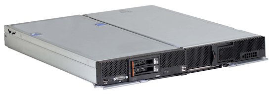
Figure 6. Flex System Storage Expansion Node (right) attached to a compute node (left)
The ordering information for the Storage Expansion Node is shown in the following table.
Table 15. Ordering part number and feature code
| Part number | Feature code* | Description | Maximum supported |
| 68Y8588 | A3JF | Flex System Storage Expansion Node | 1 |
The Storage Expansion Node has the following features:
- Connects directly to supported compute nodes via a PCIe 3.0 interface to the compute node's expansion connector (See Figure 3)
- Support for 12 hot-swap 2.5-inch drive, accessible via a sliding tray
- Support for 6 Gbps SAS and SATA drives, both HDDs and SSDs
- Based on an LSI SAS2208 6 Gbps RAID on Chip (ROC) controller
- Supports RAID 0, 1, 5, 10, and 50 as standard. JBOD also supported. Optional RAID 6 and 60 with a Features on Demand upgrade.
- Optional 512 MB or 1 GB cache with cache-to-flash super capacitor offload
Note: The use of the Storage Expansion Node requires that the x240 Compute Node have both processors installed.
For more information, see the Product Guide on the Flex System Storage Expansion Node:
http://lenovopress.com/tips0914
Internal tape drives
The server does not support an internal tape drive. However, it can be attached to external tape drives using Fibre Channel connectivity.
Optical drives
The server does not support an internal optical drive option, however, you can connect an external USB optical drive. See http://support.lenovo.com/en/documents/pd011281 for information about available external optical drives from Lenovo.
Note: The USB port on the compute nodes supply up to 0.5 A at 5 V. For devices that require more power, an additional power source will be required.
Embedded 10Gb Virtual Fabric Adapter
Some models of the x240 -- those with a model of the form 8737-x4x -- include an Embedded 10Gb Virtual Fabric Adapter (VFA, also known as LAN on Motherboard or LOM) built into the system board. Table 2 lists the models of the x240 include the Embedded 10Gb Virtual Fabric Adapter. Each x240 model that includes the embedded 10Gb VFA also has the Compute Node Fabric Connector installed in I/O connector 1 (and physically screwed onto the system board) to provide connectivity to the Enterprise Chassis midplane. Figure 3 shows the location of the Fabric Connector.
The Fabric Connector enables port 1 on the embedded 10Gb VFA to be routed to I/O module bay 1 and port 2 to be routed to I/O module bay 2. The Fabric Connector can be unscrewed and removed, if required, to allow the installation of an I/O adapter on I/O connector 1.
The Embedded 10Gb VFA is based on the Emulex BladeEngine 3R (BE3R), which is a single-chip, dual-port 10 Gigabit Ethernet (10GbE) Ethernet Controller.
These are some of the features of the Embedded 10Gb VFA:
- PCI-Express Gen2 x8 host bus interface
- Supports connection to 10 Gb and 1 Gb Flex System Ethernet switches
- Supports multiple virtual NIC (vNIC) functions
- TCP/IP Offload Engine (TOE enabled)
- SR-IOV capable
- RDMA over TCP/IP capable
- iSCSI and FCoE upgrade offering via FoD
The following table lists the ordering information for the Virtual Fabric Advanced Software Upgrade (LOM), which enables the iSCSI and FCoE support on the Embedded 10Gb Virtual Fabric Adapter.
Withdrawn: Virtual Fabric Advanced Software Upgrade (LOM) is now withdrawn from marketing.
Table 16. Feature on Demand upgrade for FCoE and iSCSI support
| Part number | Feature code |
Description | Maximum supported |
| 90Y9310 | A2TD | Virtual Fabric Advanced Software Upgrade (LOM) | 1 |
CN4022 2-port 10Gb Converged Adapter
Some models of the x240 -- those with a model of the form 8737-xMx -- include the Flex System CN4022 2-port 10Gb Converged Adapter installed in slot 1. Table 2 lists the models with this adapter standard. These models require that a compatible Ethernet switch be installed in I/O module bays 1 and 2 of the chassis.
The features of the CN4022 2-port 10Gb Converged Adapter include the following features:
- One Broadcom BCM57840 ASIC
- Connection to either 1 Gb or 10 Gb data center infrastructure (1 Gb and 10 Gb auto-negotiation)
- PCI Express 3.0 x8 host interface
- Full line-rate performance
- Supports 10 Gb Ethernet, FCoE, and iSCSI out of the box (no Features on Demand upgrade required)
- Supports vNIC - Switch Independent Mode
For details about this adapter, see the Product Guide:
http://lenovopress.com/tips1087
I/O expansion options
The x240 has two I/O expansion connectors for attaching I/O adapter cards. There is a third expansion connector designed to connect an expansion node such as the PCIe Expansion Node. The I/O expansion connectors are a very high-density 216-pin PCIe connector. Installing I/O adapter cards allows the server to connect with switch modules in the Flex System Enterprise Chassis. Each slot has a PCI Express 3.0 x16 host interface and both slots support the same form-factor adapters.
The following figure shows the location of the I/O expansion connectors.
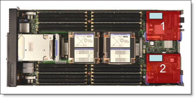
Figure 7. Location of the I/O adapter slots in the Flex System x240 Compute Node
All I/O adapters are the same shape and can be used in any available slot.. A compatible switch or pass-through module must be installed in the corresponding I/O bays in the chassis, as indicated in the following table. Installing two switches means that all ports of the adapter are enabled, which improves performance and network availability.
| I/O adapter slot in the server | Port on the adapter | Corresponding I/O module bay in the chassis |
| Slot 1 | Port 1 | Module bay 1 |
| Port 2 | Module bay 2 | |
| Port 3 (for 4-port cards) | Module bay 1 | |
| Port 4 (for 4-port cards) | Module bay 2 | |
| Slot 2 | Port 1 | Module bay 3 |
| Port 2 | Module bay 4 | |
| Port 3 (for 4-port cards) | Module bay 3 | |
| Port 4 (for 4-port cards) | Module bay 4 |
The following figure shows the location of the switch bays in the Flex System Enterprise Chassis.
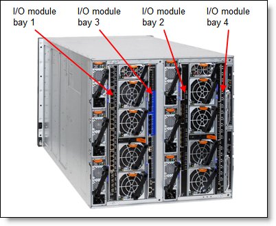
Figure 8. Location of the switch bays in the Flex System Enterprise Chassis
The following figure shows how two-port adapters are connected to switches installed in the chassis.
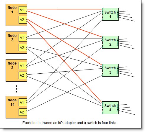
Figure 9. Logical layout of the interconnects between I/O adapters and I/O modules
Network adapters
As described in "Embedded 10Gb Virtual Fabric Adapter," certain models (those with a model number of the form 8737-x4x or 8737-xDx) have a 10Gb Ethernet controller on the system board, and its ports are routed to the midplane and switches installed in the chassis via a Compute Note Fabric Connector that takes the place of an adapter in I/O slot 1.
Models without the Embedded 10Gb Virtual Fabric Adapter (those with a model number of the form 8737-x2x) do not include any other Ethernet connections to the Enterprise Chassis midplane as standard. Therefore, for those models, an I/O adapter must be installed in either I/O connector 1 or I/O connector 2 to provide network connectivity between the server and the chassis midplane and ultimately to the network switches.
The following table lists the supported network adapters and upgrades. Adapters can be installed in either slot. However, compatible switches must be installed in the corresponding bays of the chassis. All adapters can also be installed in the PCIe Expansion Node. The "Maximum supported" column indicates the number of adapter than can be installed in the server and in the PCIe Expansion Node (PEN).
Table 18. Network adapters
| Part number | Feature code |
Description | Number of ports |
Maximum supported (x240* / PEN) |
| 40 Gb Ethernet | ||||
| 90Y3482 | A3HK | Flex System EN6132 2-port 40Gb Ethernet Adapter | 2 | 2 / None |
| 10 Gb Ethernet | ||||
| 88Y5920 | A4K3 | Flex System CN4022 2-port 10Gb Converged Adapter | 2 | 2 / 2 |
| 00AG590 | ATBS | Flex System CN4054S 4-port 10Gb Virtual Fabric Adapter | 4 | 2 / 2 |
| 00AG594 | ATBU | Flex System CN4054S 4-port 10Gb Virtual Fabric Adapter SW Upgrade (FoD upgrade for 00AG590) | License | 2 / 2 |
| 90Y3466 | A1QY | Flex System EN4132 2-port 10 Gb Ethernet Adapter | 2 | 2 / 2 |
| 1 Gb Ethernet | ||||
| 49Y7900 | A10Y | Flex System EN2024 4-port 1 Gb Ethernet Adapter | 4 | 2 / 2 |
| InfiniBand | ||||
| 90Y3454 | A1QZ | Flex System IB6132 2-port FDR InfiniBand Adapter | 2 | 2 / 2 |
* For x4x models (where the Embedded 10Gb Virtual Fabric Adapter standard), and for xMx models (where a CN4022 2-port 10Gb Converged Adapter is standard), only one extra adapter can be installed in the compute node.
For adapter-to-switch compatibility, see the Flex System Interoperability Guide:
http://lenovopress.com/fsig
Storage host bus adapters
The following table lists storage HBAs supported by the x240 server, both internally in the compute node and in the PCIe Expansion Node.
Table 19. Storage adapters
| Part number | Feature code |
Description | Number of ports |
Maximum supported (x240* / PEN) |
| Fibre Channel | ||||
| 88Y6370 | A1BP | Flex System FC5022 2-port 16Gb FC Adapter | 2 | 2 / 2 |
| 95Y2386 | A45R | Flex System FC5052 2-port 16Gb FC Adapter | 2 | 2 / 2 |
| 95Y2391 | A45S | Flex System FC5054 4-port 16Gb FC Adapter | 4 | 2 / 2 |
| 69Y1942 | A1BQ | Flex System FC5172 2-port 16Gb FC Adapter | 2 | 2 / 2 |
| 69Y1938 | A1BM | Flex System FC3172 2-port 8Gb FC Adapter | 2 | 2 / 2 |
| 95Y2375 | A2N5 | Flex System FC3052 2-port 8Gb FC Adapter | 2 | 2 / 2 |
* For x4x models (where the Embedded 10Gb Virtual Fabric Adapter standard), and for xMx models (where a CN4022 2-port 10Gb Converged Adapter is standard), only one extra adapter can be installed in the compute node.
For adapter-to-switch compatibility, see the Flex System Interoperability Guide:
http://lenovopress.com/fsig
PCIe Flash Storage adapters
The compute node supports the PCIe Flash Storage Adapters when installed in an attached PCIe Expansion Node (PEN), however the PEN is now withdrawn from marketing.
For customers who already have x240 compute nodes with attached PCIe Expansion Nodes, see the PCIe Expansion Node Product Guide for details about supported adapters: https://lenovopress.com/tips0906-flex-system-pcie-expansion-node
GPUs and coprocessors
The compute node supports GPUs when installed in an attached PCIe Expansion Node (PEN), however the PEN is now withdrawn from marketing.
For customers who already have x240 compute nodes with attached PCIe Expansion Nodes, see the PCIe Expansion Node Product Guide for details about supported adapters: https://lenovopress.com/tips0906-flex-system-pcie-expansion-node
Power supplies
Server power is derived from the power supplies installed in the chassis. There are no server options regarding power supplies.
Integrated virtualization
The x240 supports the ESXi hypervisor on a USB memory key via the x240 USB Enablement Kit. This kit offers two internal USB ports. The x240 USB Enablement Kit and the supported USB memory keys are listed in the following table.
There are two types of USB keys, preloaded keys or blank keys. Blank keys allow you to download a Lenovo customized version of ESXi and load it onto the key. Preload keys are shipped with a specific version of ESXi already loaded. The x240 supports one or two keys installed, but only certain combinations:
Supported combinations:
- One preload key
- One blank key
- One preload key and one blank key
- Two blank keys
Unsupported combinations:
- Two preload keys
Installing two preloaded keys will prevent ESXi from booting as described in http://kb.vmware.com/kb/1035107. Having two keys installed provides a backup boot device. both devices are listed in the boot menu, which allows you to boot from either device or to set one as a backup in case the first one gets corrupted.
Note: The x240 USB Enablement Kit and USB memory keys are not supported if the SSD Expansion Kit (90Y4391) is already installed, because these kits occupy the same location in the server.
Withdrawn from marketing: x240 USB Enablement Kit is now withdrawn from marketing.
Table 20. Virtualization options
| Part number | Feature code |
Description | Maximum supported |
| 49Y8119 | A3A3 | x240 USB Enablement Kit | 1 |
| 41Y8298 | A2G0 | Blank USB Memory Key for VMware ESXi Downloads | 2 |
| 41Y8300 | A2VC | USB Memory Key for VMware ESXi 5.0 | 1 |
| 41Y8307 | A383 | USB Memory Key for VMware ESXi 5.0 Update1 | 1 |
| 41Y8311 | A2R3 | USB Memory Key for VMware ESXi 5.1 | 1 |
| 41Y8382 | A4WZ | USB Memory Key for VMware ESXi 5.1 Update 1 | 1 |
| 41Y8385 | A584 | USB Memory Key for VMware ESXi 5.5 | 1 |
Light path diagnostics
For quick problem determination when located physically at the server, the x240 offers a three-step guided path:
- The Fault LED on the front panel
- The light path diagnostics panel, shown in the following figure.
- LEDs next to key components on the system board
The x240 light path diagnostics panel is visible when you remove the server from the chassis. The panel is located on the top right-hand side of the compute node, as shown in the following figure.
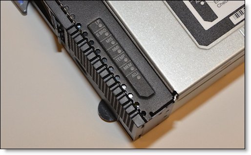
Figure 10. Location of x240 light path diagnostics panel
To illuminate the light path diagnostics LEDs, power off the compute node, slide it out of the chassis, and press the power button. The power button doubles as the light path diagnostics remind button when the server is removed from the chassis.
The meanings of the LEDs in the light path diagnostics panel are listed in the following table.
Table 21. Light path diagnostic panel LEDs
| LED | Meaning |
| LP | The light path diagnostics panel is operational. |
| S BRD | A system board error is detected. |
| MIS | A mismatch has occurred between the processors, DIMMs, or HDDs within the configuration as reported by POST. |
| NMI | A non maskable interrupt (NMI) has occurred. |
| TEMP | An over-temperature condition occurs that was critical enough to shut down the server. |
| MEM | A memory fault has occurred. The corresponding DIMM error LEDs on the system board are also lit. |
| ADJ | A fault is detected in the adjacent expansion unit (if installed). |
Remote management
The server contains an Integrated Management Module II (IMM2), which interfaces with the advanced management module in the chassis. The combination of these provides advanced service-processor control, monitoring, and an alerting function. If an environmental condition exceeds a threshold or if a system component fails, LEDs on the system board are lit to help you diagnose the problem, the error is recorded in the event log, and you are alerted to the problem. A virtual presence capability comes standard for remote server management.
Remote server management is provided through industry-standard interfaces:
- Intelligent Platform Management Interface (IPMI) Version 2.0
- Simple Network Management Protocol (SNMP) Version 3
- Common Information Model (CIM)
- Web browser
The server also supports virtual media and remote control features, which provide the following functions:
- Remotely viewing video with graphics resolutions up to 1600x1200 at 75 Hz with up to 23 bits per pixel, regardless of the system state
- Remotely accessing the server using the keyboard and mouse from a remote client
- Mapping the CD or DVD drive, diskette drive, and USB flash drive on a remote client, and mapping ISO and diskette image files as virtual drives that are available for use by the server
- Uploading a diskette image to the IMM2 memory and mapping it to the server as a virtual drive
- Capturing blue-screen errors
Operating system support
The server supports the following operating systems:
- Microsoft Windows HPC Server 2008 SP1
- Microsoft Windows Server 2008 Datacenter x64 SP2
- Microsoft Windows Server 2008 Enterprise x64 SP2
- Microsoft Windows Server 2008 R2 SP1
- Microsoft Windows Server 2008 Standard x64 SP2
- Microsoft Windows Server 2008 Web x64 SP2
- Microsoft Windows Server 2012
- Microsoft Windows Server 2012 R2
- Red Hat Enterprise Linux 5.9 Xen x64
- Red Hat Enterprise Linux 5.9 x64
- Red Hat Enterprise Linux 5.10 Xen x64
- Red Hat Enterprise Linux 5.10 x64
- Red Hat Enterprise Linux 6.4 x64
- Red Hat Enterprise Linux 6.5 x64
- Red Hat Enterprise Linux 6.6 x64
- Red Hat Enterprise Linux 6.7 x64
- Red Hat Enterprise Linux 6.8 x64
- Red Hat Enterprise Linux 6.10 x64
- Red Hat Enterprise Linux 7.0
- Red Hat Enterprise Linux 7.1
- Red Hat Enterprise Linux 7.2
- Red Hat Enterprise Linux 7.3
- Red Hat Enterprise Linux 7.4
- Red Hat Enterprise Linux 7.5
- Red Hat Enterprise Linux 7.6
- SUSE Linux Enterprise Server 11 Xen x64 SP3
- SUSE Linux Enterprise Server 11 Xen x64 SP4
- SUSE Linux Enterprise Server 11 x64 SP3
- SUSE Linux Enterprise Server 11 x64 SP4
- SUSE Linux Enterprise Server 12
- SUSE Linux Enterprise Server 12 SP1
- SUSE Linux Enterprise Server 12 SP2
- SUSE Linux Enterprise Server 12 SP3
- SUSE Linux Enterprise Server 12 SP4
- SUSE Linux Enterprise Server 12 Xen
- SUSE Linux Enterprise Server 12 Xen SP1
- SUSE Linux Enterprise Server 12 Xen SP2
- SUSE Linux Enterprise Server 12 Xen SP3
- SUSE Linux Enterprise Server 12 Xen SP4
- VMware ESXi 5.0 U2
- VMware ESXi 5.0 U3
- VMware ESXi 5.1 U2
- VMware ESXi 5.1 U3
- VMware ESXi 5.1U1
- VMware ESXi 5.5
- VMware ESXi 5.5 U1
- VMware ESXi 5.5 U2
- VMware ESXi 5.5 U3
- VMware ESXi 6.0
- VMware ESXi 6.0 U1
- VMware ESXi 6.0 U2
- VMware ESXi 6.0 U3
For a complete list of supported, certified and tested operating systems, plus additional details and links to relevant web sites, see the Operating System Interoperability Guide: https://lenovopress.com/osig#servers=x240-8737-e5-v2
Physical specifications
Dimensions and weight (approximate):
- Height: 56 mm (2.2 in)
- Depth: 492 mm (19.4 in)
- Width: 217 mm (8.6 in)
- Maximum weight: 7.1 kg (15.6 lb)
Shipping dimensions and weight (approximate):
- Height: 197 mm (7.8 in)
- Depth: 603 mm (23.7 in)
- Width: 430 mm (16.9 in)
- Weight: 8 kg (17.6 lb)
Supported environment
The Flex System x240 compute node complies with ASHRAE Class A3 specifications.
This is the supported operating environment:
Power on:
- Temperature: 5 - 40 °C (41 - 104 °F)
- Humidity, non-condensing: -12 °C dew point (10.4 °F) and 8 - 85% relative humidity
- Maximum dew point: 24 °C (75 °F)
- Maximum altitude: 3048 m (10,000 ft)
- Maximum rate of temperature change: 5 °C/hr (41 °F/hr)
Power off:
- Temperature: 5 - 45 °C (41 - 113 °F)
- Relative humidity: 8 - 85%
- Maximum dew point: 27 °C (80.6 °F)
Storage (non-operating):
- Temperature: 1 - 60 °C (33.8 - 140 °F)
- Altitude: 3050 m (10,006 ft)
- Relative humidity: 5 - 80%
- Maximum dew point: 29 °C (84.2°F)
Shipment (non-operating):
- Temperature: -40 - 60 °C (-40 - 140 °F)
- Altitude: 10,700 m (35,105 ft)
- Relative humidity: 5 - 100%
- Maximum dew point: 29 °C (84.2 °F)
Warranty
The system has a three-year warranty with 24x7 standard call center support and 9x5 Next Business Day onsite coverage. Also available are Lenovo Services warranty maintenance upgrades and post-warranty maintenance agreements, with a well-defined scope of services, including service hours, response time, term of service, and service agreement terms and conditions.
Lenovo warranty service upgrade offerings are region-specific. Not all warranty service upgrades are available in every region. For more information about Lenovo warranty service upgrade offerings that are available in your region, go to the Data Center Advisor and Configurator website http://dcsc.lenovo.com, then do the following:
- In the Customize a Model box in the middle of the page, select the Services option in the Customization Option dropdown menu
- Enter in the machine type & model of the system
- From the search results, you can click either Deployment Services or Support Services to view the offerings
The following table explains warranty service definitions in more detail.
| Term | Description |
|---|---|
| On-site service | A service technician will arrive at the client’s location for equipment service. |
| 24x7x2 hour | A service technician is scheduled to arrive at the client’s location within two hours after remote problem determination is completed. Lenovo provides service around the clock, every day, including Lenovo holidays. |
| 24x7x4 hour | A service technician is scheduled to arrive at the client’s location within four hours after remote problem determination is completed. Lenovo provides service around the clock, every day, including Lenovo holidays. |
| 9x5x4 hour | A service technician is scheduled to arrive at the client’s location within four business hours after remote problem determination is completed. Lenovo provides service 8:00 am - 5:00 pm in the client's local time zone, Monday-Friday, excluding Lenovo holidays. For example, if a customer reports an incident at 3:00 pm on Friday, the technician will arrive by 10:00 am the following Monday. |
| 9x5 next business day | A service technician is scheduled to arrive at the client’s location on the business day after remote problem determination is completed. Lenovo provides service 8:00 am - 5:00 pm in the client's local time zone, Monday - Friday, excluding Lenovo holidays. Calls received after 4:00 pm local time require an extra business day for service dispatch. Next business day service is not guaranteed. |
| Committed Repair | Problems receive priority handling so that repairs are completed within the committed time of 6, 8, or 24 hours. Lenovo provides service 24 hours/day, every day, including Lenovo holidays. |
The following Lenovo warranty service upgrades are available:
- Warranty and maintenance service upgrades:
- Three, four, or five years of 9x5 or 24x7 service coverage
- Onsite response from next business day to 2 or 4 hours
- Committed repair service
- Warranty extension of up to 5 years
- Post warranty extensions
- Committed Repair Service
Committed Repair Services enhances the level of Warranty Service Upgrade or Post Warranty/Maintenance Service offering associated with the selected systems. Offerings vary and are available in select countries.
- Priority handling to meet defined time frames to restore the failing machine to good working condition
- Committed repair service levels are measured within the following coverage hours:
- 24x7x6: Service performed 24 hours per day, 7 days per week, within 6 hours
- 24x7x8: Service performed 24 hours per day, 7 days per week, within 8 hours
- 24x7x24: Service performed 24 hours per day, 7 days per week, within 24 hours
- Hard Disk Drive Retention
Lenovo’s Hard Disk Drive Retention (HDDR) service is a multi-drive hard drive retention offering that ensures your data is always under your control, regardless of the number of hard drives that are installed in your Lenovo server. In the unlikely event of a hard drive failure, you retain possession of your hard drive while Lenovo replaces the failed drive part. Your data stays safely on your premises, in your hands. The Hard Drive Retention service can be purchased in convenient bundles with our warranty upgrades and extensions.
- Microcode Support
Keeping microcode current helps prevent hardware failures and security exposure. There are two levels of service: analysis of the installed base and analysis and update where required. Offerings vary by region and can be bundled with other warranty upgrades and extensions.
- Remote Technical Support Services (RTS)
RTS provides comprehensive technical call center support for covered servers, storage, operating systems, and applications. Providing a single source for support of hardware and software issues, RTS can reduce problem resolution time, decreasing the cost to address technical problems and increasing uptime. Offerings are available for Windows, Linux, IBM Systems Director, VMware, Microsoft business applications, and Lenovo System x storage devices, and IBM OEM storage devices.
Regulatory compliance
The server conforms to the following standards:
- ASHRAE Class A3
- FCC - Verified to comply with Part 15 of the FCC Rules Class A
- Canada ICES-004, issue 3 Class A
- UL/IEC 60950-1
- CSA C22.2 No. 60950-1
- NOM-019
- Argentina IEC 60950-1
- Japan VCCI, Class A
- IEC 60950-1 (CB Certificate and CB Test Report)
- China CCC (GB4943); (GB9254, Class A); (GB17625.1)
- Taiwan BSMI CNS13438, Class A; CNS14336
- Australia/New Zealand AS/NZS CISPR 22, Class A
- Korea KN22, Class A, KN24
- Russia/GOST ME01, IEC 60950-1, GOST R 51318.22, GOST R
- 51318.249, GOST R 51317.3.2, GOST R 51317.3.3
- IEC 60950-1 (CB Certificate and CB Test Report)
- CE Mark (EN55022 Class A, EN60950-1, EN55024, EN61000-3-2,
- EN61000-3-3)
- CISPR 22, Class A
- TUV-GS (EN60950-1/IEC 60950-1, EK1-ITB2000)
Lenovo Financial Services
Why wait to obtain the technology you need now? No payments for 90 days and predictable, low monthly payments make it easy to budget for your Lenovo solution.
- Flexible
Our in-depth knowledge of the products, services and various market segments allows us to offer greater flexibility in structures, documentation and end of lease options.
- 100% Solution Financing
Financing your entire solution including hardware, software, and services, ensures more predictability in your project planning with fixed, manageable payments and low monthly payments.
- Device as a Service (DaaS)
Leverage latest technology to advance your business. Customized solutions aligned to your needs. Flexibility to add equipment to support growth. Protect your technology with Lenovo's Premier Support service.
- 24/7 Asset management
Manage your financed solutions with electronic access to your lease documents, payment histories, invoices and asset information.
- Fair Market Value (FMV) and $1 Purchase Option Leases
Maximize your purchasing power with our lowest cost option. An FMV lease offers lower monthly payments than loans or lease-to-own financing. Think of an FMV lease as a rental. You have the flexibility at the end of the lease term to return the equipment, continue leasing it, or purchase it for the fair market value. In a $1 Out Purchase Option lease, you own the equipment. It is a good option when you are confident you will use the equipment for an extended period beyond the finance term. Both lease types have merits depending on your needs. We can help you determine which option will best meet your technological and budgetary goals.
Ask your Lenovo Financial Services representative about this promotion and how to submit a credit application. For the majority of credit applicants, we have enough information to deliver an instant decision and send a notification within minutes.
Trademarks
Lenovo and the Lenovo logo are trademarks or registered trademarks of Lenovo in the United States, other countries, or both. A current list of Lenovo trademarks is available on the Web at https://www.lenovo.com/us/en/legal/copytrade/.
The following terms are trademarks of Lenovo in the United States, other countries, or both:
Lenovo®
ServerProven®
System x®
XClarity®
The following terms are trademarks of other companies:
Intel®, the Intel logo and Xeon® are trademarks of Intel Corporation or its subsidiaries.
Linux® is the trademark of Linus Torvalds in the U.S. and other countries.
Microsoft, RemoteFX, Windows, and Windows Server are trademarks of Microsoft Corporation in the United States, other countries, or both.
IBM® and ibm.com® are trademarks of IBM in the United States, other countries, or both.
Other company, product, or service names may be trademarks or service marks of others.


