

Top
Authors
Updated
18 Sep 2025Form Number
LP1556PDF size
18 pages, 2.3 MBSubscribed to LP1556.
Thank you for your feedback.
Table of Contents
Abstract
The 1U Switched & Monitored 3-Phase Power Distribution Units (PDUs) make it quick and simple to deploy, protect, and manage your high-availability rack environment. These space efficient and power dense PDUs were co-designed by Vertiv and Lenovo and come in a variety of 1U designs available to meet the requirements of your most power-demanding systems.
This product guide provides essential presales information to understand the 1U Switched and Monitored PDUs and their key features, specifications, and compatibility. This guide is intended for technical specialists, sales specialists, sales engineers, IT architects, and other IT professionals who want to learn more about the Switched and Monitored PDUs and consider their use in IT solutions.
Change History
Changes in the Septemeber 18, 2025 update:
- Marked the following withdrawn under Specifications section
- 4PU7A77467, 4PU7A77469, 4PU7A77468, 4PU7A81118
Introduction
The 1U Switched and Monitored 3-Phase Power Distribution Units (PDUs) make it quick and simple to deploy, protect, and manage your high-availability rack environment. These space efficient and power dense PDUs were co-designed by Vertiv and Lenovo and come in the following 1U designs available to meet the requirements of your most power-demanding systems:
- 18x Combination outlets C13/C19 with 80A 3-phase Delta input
- 18x Combination outlets C13/C19 with 48A 3-phase Wye input (ETL certification)
- 12x Combination outlets C13/C19 with 60A 3-phase Delta input
- 12x Combination outlets C13/C19 with 32A 3-phase Wye input 1U
- 18x Combination outlets C13/C19 with 48A 3-phase Wye input (CE certification)
The outlets (receptacles) on the PDUs give administrators the ability to remotely turn on, turn off, or reboot power at each outlet to power cycle unresponsive IT equipment. Outlet level monitoring gives a comprehensive view of outlet power usage via remote network access. They provide on and off functionality to allow for power sequencing and to help prevent unintended overloading. The following figure shows the PDU with 18 rear-facing outlets.
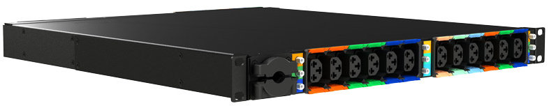
Figure 1. Lenovo 1U Switched & Monitored 3-Phase PDU - 18-outlet model (attached line cord removed to show outlets)
Did you know?
With ever growing power densities in today’s rack environments, it is all too easy to add load in the wrong place and trigger an overload event. The Switched and Monitored PDU offerings can minimize this impact, providing the ability to quickly recover with resettable circuit breakers for each designated bank of outlets (receptacles), referred to as circuits or load groups. Breakers are color coded to the outlets in a particular circuit to aid in configuration, installation, and maintenance. Furthermore, these PDUs also offer individual outlet remote monitoring and switching (on/off), which allows for remote power sequencing and further helping to prevent unintended PDU overloading.
What is a switched and monitored PDU?
A power distribution unit (PDU) is a highly reliable, multiple outlet power strip designed to consolidate line cords within the rack and distribute conditioned power from an uninterruptible power supply (UPS) or utility power to servers and other IT equipment. The PDU efficiently distributes power within the rack and provides fault-tolerant power redundancy for high availability requirements.
- Switched & monitored PDUs: These are advanced power management solutions, providing power monitoring at the outlet level, with increased accuracy at low amperages, for more precise views of power consumption down to the individual server level instead of at the consolidated load group. These PDUs also offer management via a web-based interface which includes individual outlet switching (on/off). Outlet switching allows for remote power sequencing and helps prevent unintended PDU overloading.
Part number information
The following tables provide the ordering part numbers and feature codes for the PDUs.
The PDUs include the following items:
- Power distribution unit with attached power cord
- Mounting rails for supported rack cabinets - horizontal and vertical (side pocket) mounting
- Rack mounting hardware kit including M6 cage nuts and supporting screws/nuts
The Environmental Sensor includes the following:
- Vertiv GT3HD Sensor unit
- Probe with a 3 foot (0.9m) attached cable that connects to the sensor unit
- Probe with a 6-foot (1.8m) attached cable that connects to the sensor unit
- 10-foot (3m) cable to connect the sensor unit to the PDU (RJ12 connectors)
Note: An Environmental Sensor is not included with the PDU and will need to be ordered separately (4M27A13686, BNDX).
The following countries are not supported for PDUs: 4PU7A90809 & 4PU7A90811:
- Belarus, Russian Federation (RUCIS geo)
- Nigeria (MEA geo)
Features
The PDUs have the following features
- 1U form factor allows for high-current deployments in a compact PDU. Can be installed vertically in the side pocket of a rack cabinet or horizontally at the rear of a rack space (1U rack unit)
- Combination C13/C19 outlets (receptacles) accommodate ever-changing rack power requirements with the flexibility to connect C14 or C20 plugs in the same outlet.
- Fully monitored and managed PDU including Residual Current Metering Type B
- Interchangeable Monitoring Device (IMD) is hot-swappable and includes ports for serial communication, environmental monitoring, and dual Gigabit Ethernet ports to simplify management of multiple PDUs with fault-tolerant daisy chaining or IP aggregation capabilities. One of these ports can be used to connect the IMD to an existing network or both ports can be used at the same time to connect one IMD to another in a daisy-chain configuration.
- Easily identify circuits with color-coded P-Lock tabs, streamlining circuit and phase balancing with alternating outlets.
- The use of P-Lock tabs on the outlets reduce the chance of accidental removal of a power cord from the PDU (P-Lock compatible cord sets required for locking feature)
- Comprehensive power management and flexible configuration
- Supported protocols: DHCP, HTTP, HTTPS, IPv4, IPv6, LDAP, NTP, RADIUS, RSTP, SSH, SMTP, SNMP (v1/v2c/v3), Syslog, TACACS+
- Detailed data-logging for statistical analysis and diagnostics
- Easy-to-use interface to display input and output status
- Event notification through SNMP trap or email alerts
- Reliable power distribution with local and remote power monitoring options offer quick access to critical power usage information to evaluate energy usage trends and maximize uptime.
- Remote monitoring of connected devices and sensors
- Easily accessible breakers
- Remotely reboot outlets to power cycle unresponsive IT equipment or increase runtime of critical equipment upon power failure with outlet-level control
- Monitor power consumption at the outlet-level for a detailed view of power distributed to specific equipment
- Local and remote input monitoring with accuracy of +/- 1% (ANSI C12.1 and IEC 62053-21 Standards)
- Detailed data logging for statistical analysis and diagnostics
- Management using SNMP v1, SNMP v2c, and SNMP v3
Specifications
The following table compares the technical and environmental specifications of the V1 PDUs.
The following table compares the technical and environmental specifications of the V2 PDUs.
Connections
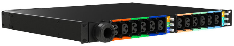
The front and rear of the PDUs is shown in the following figure.
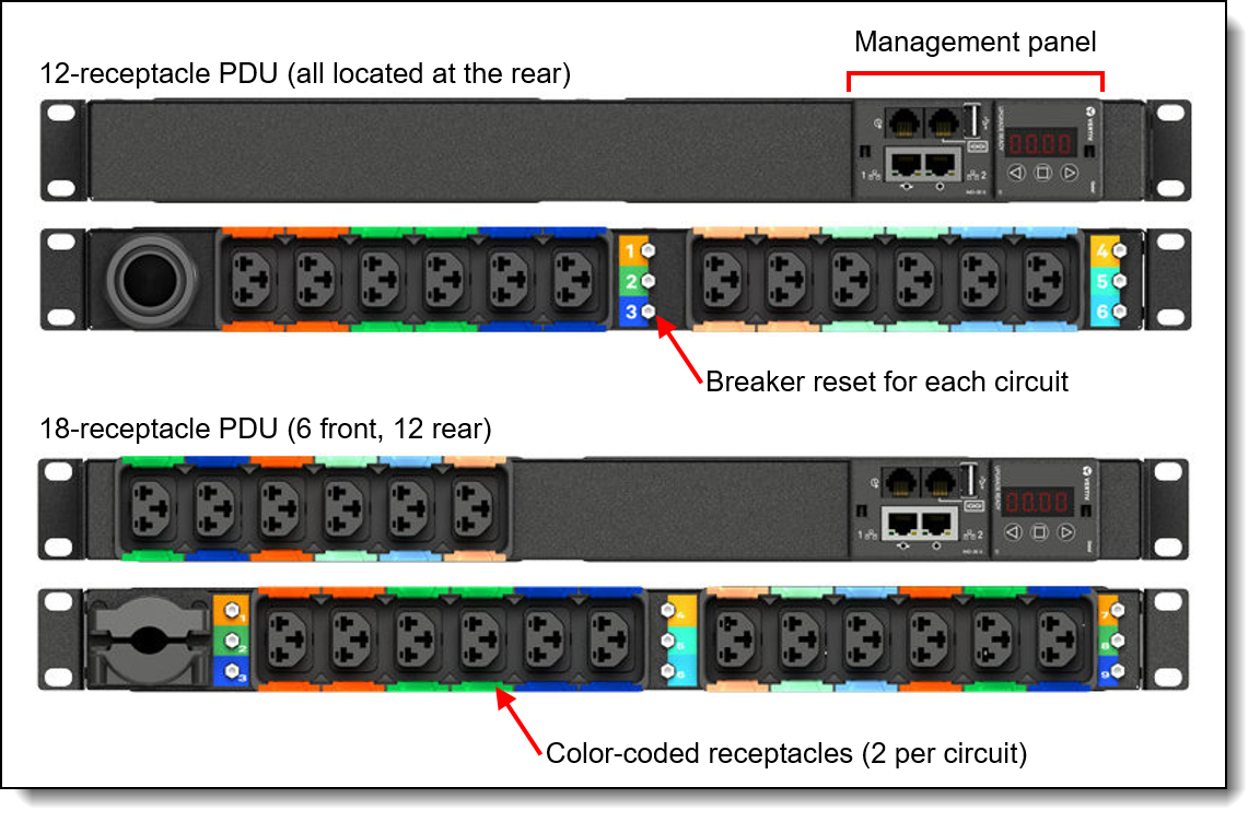
Figure 3. Front and rear views of the PDUs
For PDUs with 9 circuits (18 outlets), the circuits are the following outlet pairs and are indicated on the PDUs using colors. Note that the two outlets in a circuit are not always adjacent to each other.
- Outlets 1 and 2
- Outlets 3 and 4
- Outlets 5 and 6
- Outlets 7 and 13
- Outlets 8 and 14
- Outlets 9 and 15
- Outlets 10 and 16
- Outlets 11 and 17
- Outlets 12 and 18
For PDUs with 6 circuits (12 outlets), the circuits are the following outlet pairs. The two outlets in each circuit are adjacent to each other in these PDUs.
- Outlets 1 and 2
- Outlets 3 and 4
- Outlets 5 and 6
- Outlets 7 and 8
- Outlets 9 and 10
- Outlets 11 and 12
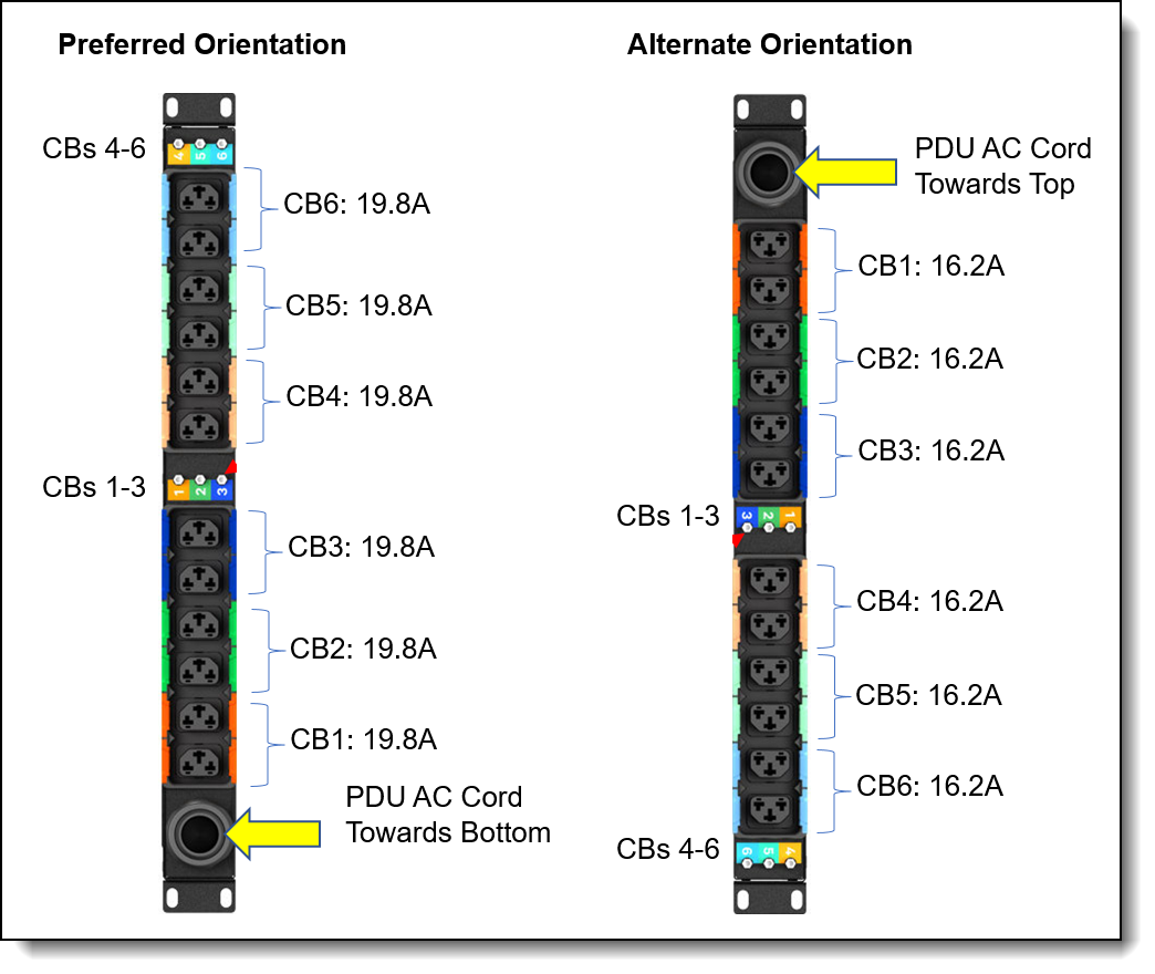
Circuit breaker ratings
The PDUs described in this product guide contain magnetic and hydraulic circuit breakers. The rating of the breakers can vary from their nominal rating based on the orientation of the PDU and consequently, the orientation of the circuit breakers within the PDU.
In particular, when a PDU is installed vertically in the side pocket of a rack, its rating can increase or decrease 10% from the nominal rating, depending on the orientation of the PDU in the side pocket. The following diagrams illustrate the rating for each breaker and the corresponding outlets protected by the breaker.
Note that if the PDU is installed horizontally in 1U slot of the rack, all of the breakers in the PDU are rated at their nominal rating of 18A.
PDUs with 9 Circuit Breakers
This section applies to the 18-outlet PDUs with 9 circuit breakers. The circuit breaker ratings are listed in the following table.
The table shows the different ratings based on the vertical orientation of the PDU. If the PDU is installed horizontally in a 1U slot of a rack, all circuit breakers are rated for 18A, regardless of whether the PDU AC cord is on the left or right.
The following figure shows the location of the circuit breakers and their ratings.

Figure 4. Circuit breaker ratings - 18-outlet PDUs
PDUs with 6 Circuit Breakers
This section applies to the 12-outlet PDUs with 6 circuit breakers. The circuit breaker ratings are listed in the following table.
The table shows the different ratings based on the vertical orientation of the PDU. If the PDU is installed horizontally in a 1U slot of a rack, all circuit breakers are rated for 18A, regardless of whether the PDU AC cord is on the left or right.
The following figure shows the location of the circuit breakers and their ratings.
Management panel
The PDUs include a local management panel, known as the Interchangeable Monitoring Device (IMD), which provides the interface and connectors to manage the PDU. The following figure shows the components and ports of the IMD.
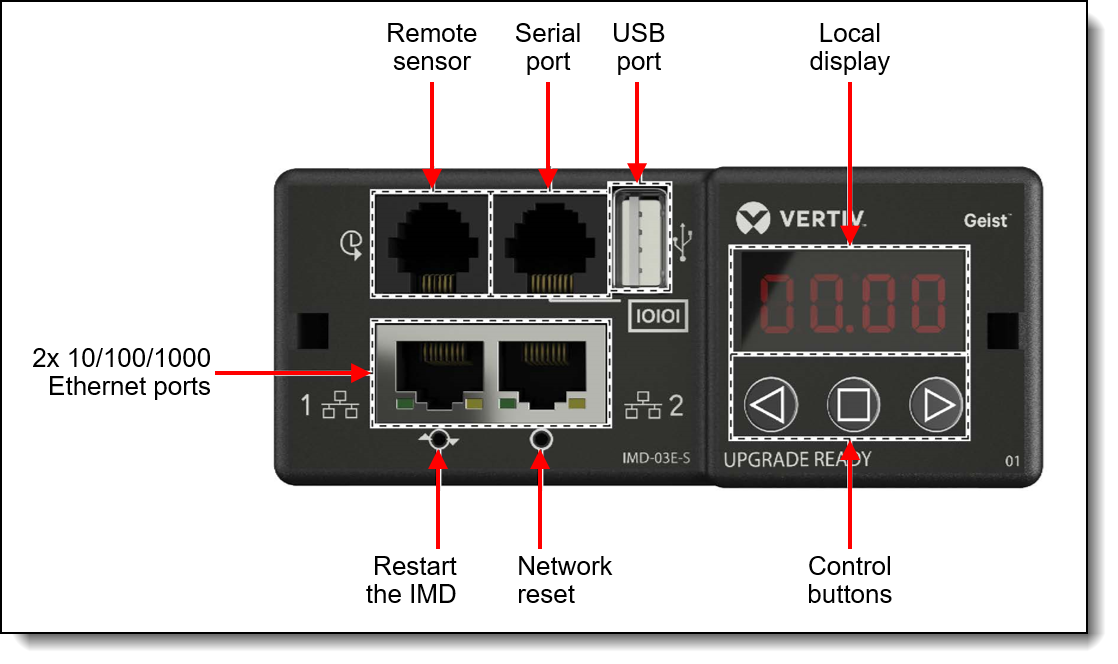
Figure 6. Local management panel (IMD)
The components of the IMD management panel are as follows:
- Dual Ethernet Ports: The dual Ethernet ports act as a two-port Ethernet switch, allowing for multiple devices to be daisy-chained.
- Hard-Reboot Button: Pressing the hard-reboot button reboots the IMD. This acts as a power-cycle for the IMD; it does not change or remove any user information.
- Network Reset Button: Holding the network-reset button for 5 seconds during normal operation will restore the default IP address and reset the user accounts.
- Local Display: The local display shows the phase, line and circuit current values (in amperes).
- Display Buttons:
- Back button: Press to decrement to previous channel. Also used to initiate a backup function.
- Forward button: Press to increment to next channel. Also used to initiate a restore function
- Center button: Toggle between scrolling and static display modes. Also used to initiate a reset function.
- Remote Sensor Port: RJ-12 port for connecting an environmental sensor.
- Serial Port: RS-232 via RJ-45 port.
- USB Port: USB port used to upload firmware, backup/restore device configuration or expand logging capacity via USB storage device. Provides up to 100mA power capacity for USB-connected devices.
Tips:
- Pressing both Left and Right buttons together flips the display 180 degrees
- Pressing the Left and Center buttons together displays the IPv4 address of the IMD
Environmental Sensor
The Environmental Sensor, part number 4M27A13686, is an optional device used to report local temperature and humidity values at its installed location and make that information available to the PDU. The Environmental Sensor connects to the PDU via the Remote Sensor port of the IMD of the PDU as shown in the Management panel section. The following figure shows the Environmental Sensor.
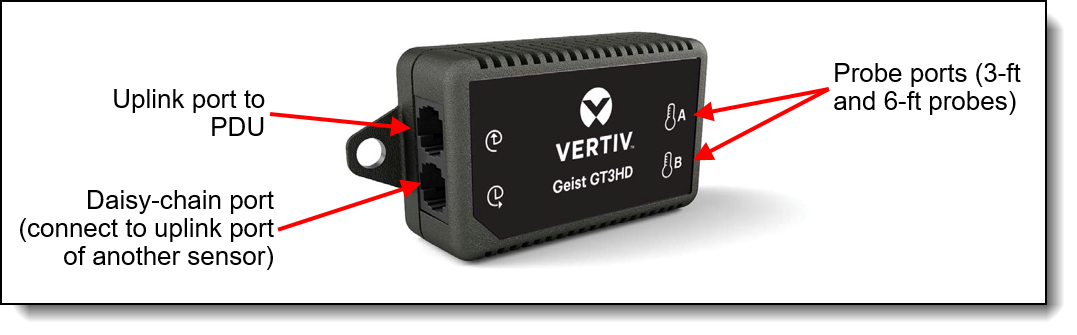
Figure 7. Environmental Sensor
Features of the Environmental Sensor - Temperature & Humidity , 4M27A13686:
- Vertiv GT3HD sensor with two remote probes on 3ft and 6ft cables
- Provide temperature, humidity, and dew point information
- Receive alerts when a threshold is breached to ensure out-of-range conditions are addressed before resulting in downtime.
- Strategically monitor data center, server room and network closet environments to protect critical infrastructure.
- Simple installation and configuration
- Connects to PDU via RJ12 cabling
- Supports daisy-chaining of additional environmental sensors in other rack cabinets, up to 16 sensors
- Temperature measurement range: -20°C to 80°C (-4°F to 176°F) at +/- 0.5°C accuracy
- Humidity measurement range 5% to 95% at accuracy +/- 3%
- Dew point measurement range -50°C to 85°C (-58°F to 185°F)
- View real time sensor data from a secure web interface.
The probes are attached to the sensor and should be positioned to allow monitoring of key devices in the rack cabinet, as shown in the following figure. The figure also shows how multiple sensors can be daisy-chained together.
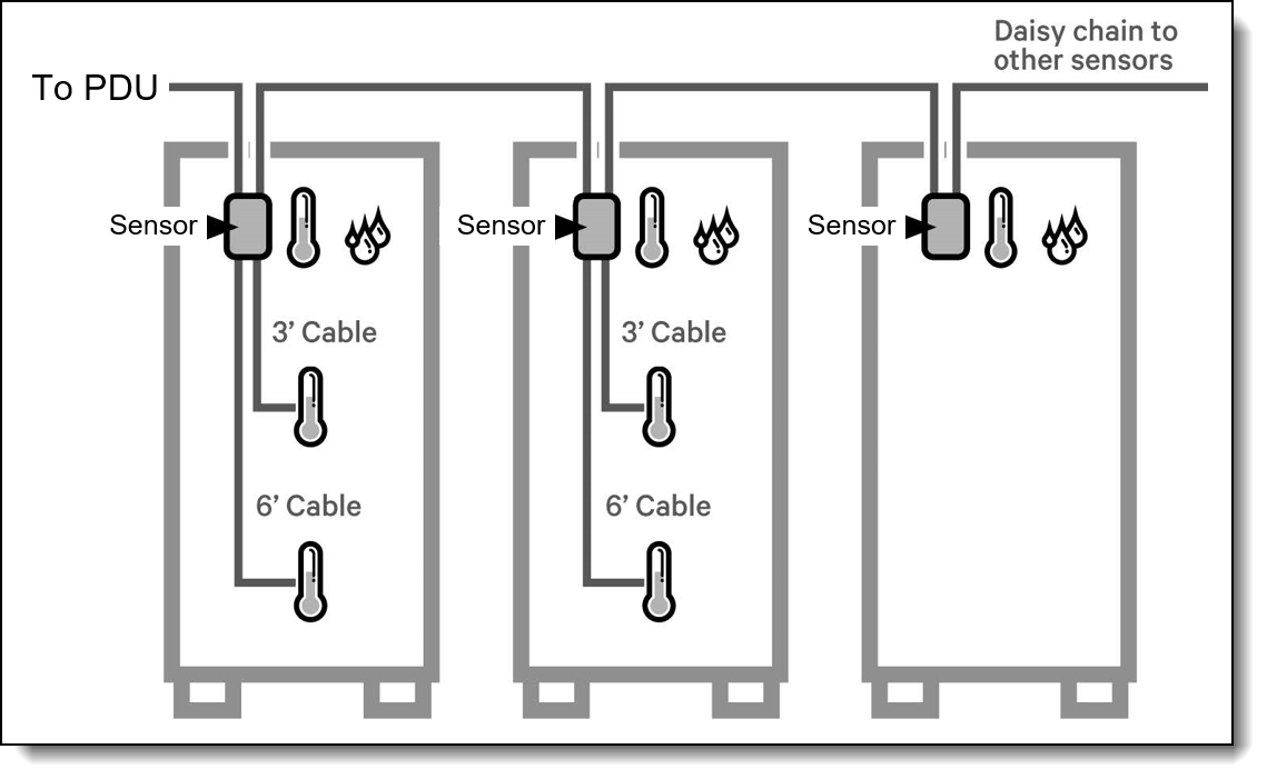
Figure 8. Connecting the sensor
Browser interface
The PDU provides a graphical user interface that you can view from a web browser. Using a web browser, you can access and monitor the PDU power outlets and output devices remotely from a computer.
The following tasks can be performed though browser interface:
- Control individual outlets (On/Off)
- Display PDU and outlet-level current, kWh, watts, output power in VA, and power factor
- Set outlet alarm thresholds
- View environmental sensor data and set traps/alarm thresholds
- Access a graphical historical view of PDU data for statistical trend analysis
- View PDU Alarms
- View Event/System Logs
Supported rack cabinets
The 1U Switched and Monitored PDUs can be installed in all 19 inch rack cabinets.
Installation can be either vertically in side pockets of the rack or horizontally in a 1U space. The PDU part numbers include the necessary rack installation hardware for either configuration.
- For specifications about these racks, see the Lenovo Rack Cabinet Reference, available from:
https://lenovopress.com/lp1287-lenovo-rack-cabinet-reference
Agency approvals
The PDUs conform to the following standards:
- FCC Part 15 Class A Conformance
- UL 62368
- RoHS Compliant
Related publications and links
For more information, see the following documents:
- User Manuals - Quick Install Guide, Installer Guide and IMD Replacement Guide
https://www.vertiv.com/en-us/support/avocent-support-lenovo/ - Lenovo Rack Cabinet Reference
https://lenovopress.com/lp1287-lenovo-rack-cabinet-reference - Lenovo Capacity Planner (LCP):
https://datacentersupport.lenovo.com/us/en/solutions/lnvo-lcp
Trademarks
Lenovo and the Lenovo logo are trademarks or registered trademarks of Lenovo in the United States, other countries, or both. A current list of Lenovo trademarks is available on the Web at https://www.lenovo.com/us/en/legal/copytrade/.
The following terms are trademarks of Lenovo in the United States, other countries, or both:
Lenovo®
Neptune®
Other company, product, or service names may be trademarks or service marks of others.
Configure and Buy
Please select a locale
Full Change History
Changes in the Septemeber 18, 2025 update:
- Marked the following withdrawn under Specifications section
- 4PU7A77467, 4PU7A77469, 4PU7A77468, 4PU7A81118
Changes in the Septemeber 18, 2025 update:
- Marked the following withdrawn under Features section
- 4PU7A77467, 4PU7A77469, 4PU7A77468, 4PU7A81118
Changes in the July 17, 2025 update:
- Removed the following not applicable to "Switched & monitored PDUs" under What is a switched and monitored pdu section
- Basic PDUs: The simplest and most cost-effective power distribution. Available with various outlet configurations and line cord options to support different systems and load requirements.
- Monitored PDUs: provides the same benefits as a Basic PDU, but adds additional advanced PDU power monitoring down to the load group. This enables businesses to have a cross-platform rack-level power and thermal view for trending analysis to improve power management.
Changes in the July 7, 2025 update:
- Removed the following note under Part number information section
- Note: The maximum load in A is not to exceed 80 % of the circuit breaker's rating.
Changes in the May 14, 2025 update:
- Removed the following withdrawn from marketing under Part number information section
- 4PU7A81118, 4PU7A77467, 4PU7A77469
Changes in the February 6, 2025 update:
- Removed the following under Circuit breaker ratings section
- Reference to Kratos
Changes in the January 9, 2025 update:
- Updated country support for the following under Part number information section
- 4PU7A90808, 4PU7A90809, 4PU7A90810, 4PU7A90811, 4PU7A90812
Changes in the October 25, 2024 update:
- Updated country support for the following under Part number information section
- 4PU7A90809, 4PU7A90811
Changes in the September 26, 2024 update:
- Updated Circuit breaker ratings - 18-outlet PDUs image under section Circuit breaker ratings
Changes in the September 24, 2024 update:
- Updated Circuit breaker ratings - 18-outlet table under section Circuit breaker ratings
Changes in the September 12, 2024 update:
- Updated country support for the following under Part number information section
- 4PU7A90808, 4PU7A90809, 4PU7A90810, 4PU7A90811, 4PU7A90812
Changes in the July 17, 2024 update:
- Updated the following rack cabinet URL under Supported rack cabinets section
- https://lenovopress.lenovo.com/lp1287-lenovo-rack-cabinet-reference#availability=Available
Changes in the June 6, 2024 update:
- Updated region availability support for the following tables
- Part number information for V1 PDUs
- Part number information for V2 PDUs
Changes in the June 5, 2024 update:
- Updated market availability support for the following under Part number information section
- 1U 18 C19/C13 switched and monitored 48A 3P WYE PDU V2 – ETL, 4PU7A90808
- 1U 18 C19/C13 switched and monitored 80A 3P Delta PDU V2, 4PU7A90810
Changes in the May 30, 2024 update:
- Updated country support for the following under Part number information section
- 1U 18 C19/C13 switched and monitored 48A 3P WYE PDU - CE, 4PU7A81118
Changes in the April 30, 2024 update:
- Added new PDUs V2 under Specifications section
- 1U 18 C19/C13 Switched and monitored 48A 3P WYE PDU V2 ETL, 4PU7A90808
- 1U 12 C19/C13 Switched and monitored 60A 3P Delta PDU V2, 4PU7A90812
- 1U 12 C19/C13 Switched and monitored 32A 3P WYE PDU V2, 4PU7A90811
- 1U 18 C19/C13 Switched and monitored 80A 3P Delta PDU V2, 4PU7A90810
- 1U 18 C19/C13 Switched and monitored 48A 3P WYE PDU V2 CE, 4PU7A90809
Changes in the June 8, 2023 update:
- Added new section Circuit breaker ratings
Changes in the April 7, 2023 update:
- Added information about the outlets that form each circuit - Connections section
Changes in the September 19, 2022 update:
- New PDUs:
- 1U 12 C19/C13 switched and monitored 60A 3P Delta PDU, 4PU7A77469
- 1U 12 C19/C13 switched and monitored 32A 3P WYE PDU, 4PU7A77468
- 1U 18 C19/C13 switched and monitored 48A 3P WYE PDU - CE, 4PU7A81118
First published: March 29, 2022
Course Detail
Employees Only Content
The content in this document with a is only visible to employees who are logged in. Logon using your Lenovo ITcode and password via Lenovo single-signon (SSO).
The author of the document has determined that this content is classified as Lenovo Internal and should not be normally be made available to people who are not employees or contractors. This includes partners, customers, and competitors. The reasons may vary and you should reach out to the authors of the document for clarification, if needed. Be cautious about sharing this content with others as it may contain sensitive information.
Any visitor to the Lenovo Press web site who is not logged on will not be able to see this employee-only content. This content is excluded from search engine indexes and will not appear in any search results.
For all users, including logged-in employees, this employee-only content does not appear in the PDF version of this document.
This functionality is cookie based. The web site will normally remember your login state between browser sessions, however, if you clear cookies at the end of a session or work in an Incognito/Private browser window, then you will need to log in each time.
If you have any questions about this feature of the Lenovo Press web, please email David Watts at dwatts@lenovo.com.


