

Top
Author
Published
27 Dec 2023Form Number
LP1877PDF size
22 pages, 1.6 MBSubscribed to LP1877.
Thank you for your feedback.
Table of Contents
Abstract
Memory Mirroring is a reliability feature offered on all Intel Xeon Scalable processor family-based platforms starting from 1st Gen processors. Memory Mirroring allows users to configure the memory in a highly reliable mode. It can replicate and store data on two pairs of DIMMs within two channels simultaneously. If a failure occurs, the memory controller switches from the primary pair of memory DIMMs to the backup pair of DIMMs.
Address Range Mirroring is a similar memory reliability feature on the Intel Xeon Scalable Family platform, however it allows greater granularity in selecting how much memory is dedicated for redundancy. Address Range Mirroring is available only Gold and Platinum level processors.
Memory Mirroring and Address Range Mirroring are designed to allow the mirroring of critical memory regions to increase the stability of physical memory.
This document presents a technical overview of the Memory Mirroring and Address Range Mirroring, and describes how to configure and use them in VMware vSphere on ThinkSystem servers. This document is intended for IT administrators who are familiar with VMware vSphere.
Introduction to Memory Mirroring
Servers based on the Intel Xeon Scalable processor family support a Reliability Availability Serviceability (RAS) feature called Memory Mirroring. Memory Mirroring allows users to configure the memory in a highly reliable mode when memory component is affected by uncorrectable fault, so that in the event of a DIMM failure the server will keep on running. It provides full memory redundancy while reducing the total system memory capacity in half. Memory channels are grouped in pairs with each channel receiving the same data. If an uncorrectable fault occurs, the memory access controller switches from the DIMMs on the primary channel to the DIMMs on the mirrored channel.
The workflow of Memory Mirroring data writes and reads are shown in the following figure.
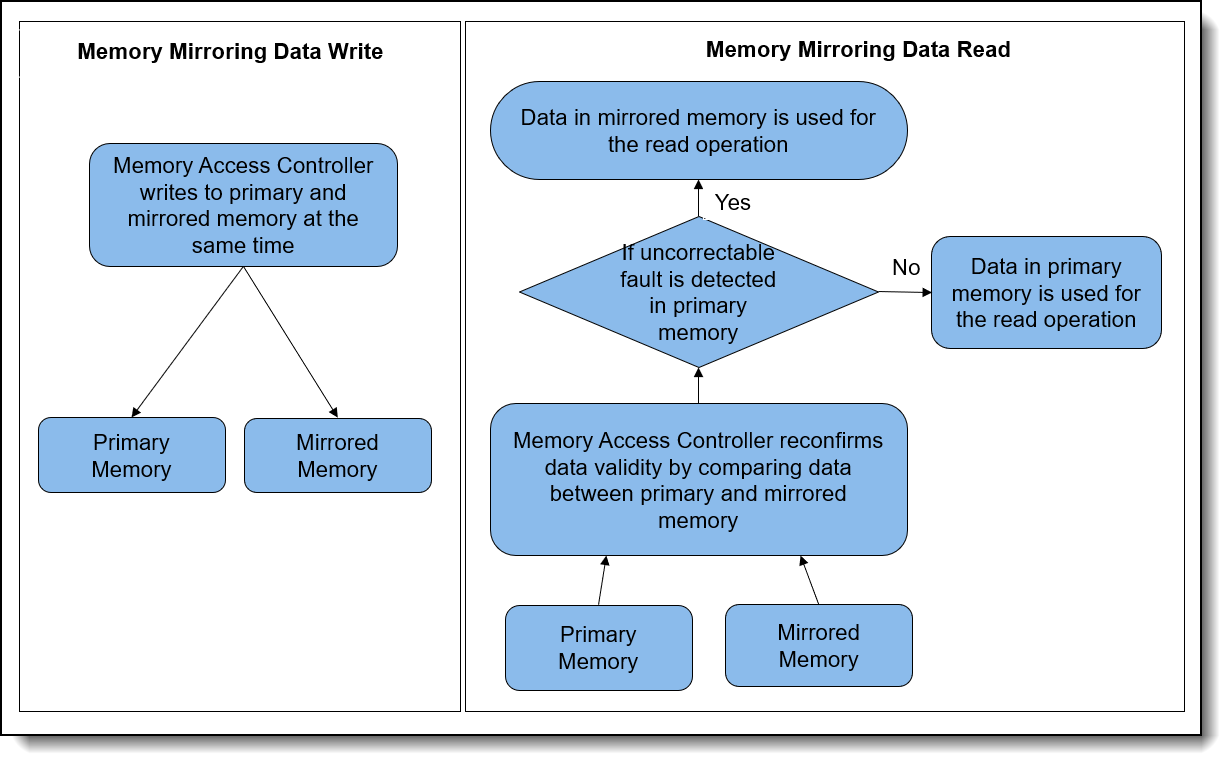
Figure 1. Workflow of Memory Mirroring data writes and reads
ThinkSystem servers with any Intel Xeon Scalable processor can support the Memory Mirroring feature. VMware ESXi supports the Memory Mirroring feature and the memory scheduler can put the memory pages consumed by critical services on reliable memory regions.
Memory mirroring reduces the maximum available memory by half of the installed memory. For example, if the server has 128 GB of installed memory, only 64 GB of addressable memory is available for ESXi when memory mirroring is enabled.
An illustration of Memory Mirroring is shown in the following figure.

Introduction to Address Range Mirroring
The Intel Xeon Gold and Platinum processors also offer support for partial memory mirroring which also called Address Range Mirroring. This feature allows greater granularity in selecting how much memory is dedicated for redundancy and it can reduce the amount of memory reserved for redundancy.
When Address Range Mirroring is used, the platform allows customer to specify a subset of total available memory for mirroring. This capability allows customers to make an appropriate trade-off between non-mirrored memory range and mirrored memory range, thus optimizing total available memory while keeping highly reliable memory range (the mirrored portion of the address space) available for mission-critical workloads and kernel space.
Lenovo ThinkSystem servers with Platinum or Gold processors can support Address Range Mirroring feature. VMware ESXi also support Address Range Mirroring feature and memory scheduler will do its best at putting all critical code and data in reliable memory. VMware refers to memory that is enabled for mirroring as reliable memory.
Address Range Mirroring can reduce the amount of memory reserved for redundancy by specify the desired subset of memory to mirror. For example, if the server has 128 GB of installed memory and mirror 25% of memory, 96 GB of addressable memory is available for ESXi when Address Range Mirroring is used. An illustration of Address Range Mirroring is shown below.

Figure 3. Address Range Mirroring
Address Range Mirroring offers the following benefits for customers:
- Provides greater granularity to memory mirroring by allowing customer to determine a range of memory addresses to be mirrored and leaving the rest of the memory in non-mirror mode.
- Reduces the amount of memory reserved for redundancy.
- Optimizes total available memory while keeping highly reliable memory range available for mission-critical workloads and kernel space.
vSphere support
Memory Mirroring is supported by all Intel Xeon Scalable processors, starting from 1st Gen processors. Address Range Mirroring is only supported by Intel Xeon Platinum processors and Intel Xeon Gold processors. The following table lists the Intel Xeon CPUs that support Memory Mirroring or Address Range Mirroring.
Memory Mirroring and Address Range Mirroring are supported in vSphere ESXi 5.5 and later versions. If the server platform supports Memory Mirroring or Address Range Mirroring feature, ESXi can put the memory pages consumed by critical services in the mirrored regions.
Reliable memory: VMware ESXi refers to memory that is mirrored as reliable memory.
If at any point of time the system has insufficient reliable memory, ESXi falls back to allocating regular memory. At that point, using the reliable memory for critical services is a best effort.
As a minimum, we recommend booting ESXi with 3GB of reliable memory. If the amount of reliable memory on a system is too small to contain all the critical services at boot time, the host might hang or PSOD. To guarantee that all the critical services remain in reliable memory, it is recommended not to exhaust the reliable memory. In other words, configuring virtual machines with more reliable memory than the host capacity is not recommended.
vmkernel and monitor are categorized as priority 0 so the memory pages consumed by them are on high priority to be put in the reliable memory area. Some system processes running on ESXi userworld are marked as memory reliable and they are categorized as priority 1. Therefore, they are secondary priority to be put on reliable memory regions.
It’s worth noting that more than the kernel can use this feature. We can also place the memory pages consumed by virtual machine (VM) on reliable memory area to protect the VMs from memory failure. They are categorized as priority 2, so they are on thirdly prioritized to be put in reliable memory area.
Note that even though vSphere ESX supports reliable memory, vSphere Distributed Resource Scheduler (DRS) does not support for reliable memory and DRS is a feature included in the vSphere Enterprise Plus.
DIMM installation
In Memory Mirroring mode, each memory module in a pair must be identical in size and architecture. The channels are grouped in pairs with each channel receiving the same data. One channel is used as a backup of the other, which provides redundancy. If a failure occurs, the memory access controller switches from the DIMMs on the primary channel to the DIMMs on the backup channel. The DIMM installation order for memory mirroring varies based on the number of processors and DIMMs installed in the server.
Address Range Mirroring is a sub-function of Memory Mirroring, so it requires the same memory installation rules and order as Memory Mirroring.
Follow the rules below when installing memory modules in Mirroring Mode:
- DIMMS are installed in pairs for each processor.
- All memory modules to be installed must be of the same type with the same capacity, frequency, voltage, and ranks.
- Mirroring can be configured across channels in the same iMC, and the total TruDDR5 memory size of the primary and secondary channels must be the same.
- 9x4 RDIMMs do not support mirroring mode.
- Partial Memory Mirroring is a sub-function of memory mirroring. It requires following the memory installation order of memory mirroring mode.
DIMM installation order for Mirroring Mode with one processor
Table 2 shows the sequence of populating memory modules for mirroring mode when only one processor is installed on ThinkSystem SR650 V3.
DIMM installation order for Mirroring Mode with two processors
The following table shows the sequence of populating memory modules for mirroring mode when two processors are installed on Lenovo ThinkSystem SR650 V3.
Refer to the following Lenovo Pubs site for more information on installing DIMMs correctly in Mirroring mode on Lenovo ThinkSystem servers:
https://pubs.lenovo.com/
For example, you can find the Memory Mirroring mode installation order for the Lenovo ThinkSystem SR650 V3 at the following web page:
https://pubs.lenovo.com/sr650-v3/memory_module_installation_order_mirroring
Server configuration
To use Memory Mirroring and Address Range Mirroring, the server configuration must meet the following requirement:
- Lenovo ThinkSystem servers with Intel Xeon processors can support Memory Mirroring.
- Lenovo ThinkSystem servers with Intel Xeon Platinum Processors or Intel Xeon Gold Processors can support Address Range Mirroring feature.
- 9x4 Dual In-line Memory Modules do not support Memory Mirroring and Address Range Mirroring.
- “ADDDC Sparing” should be disabled in UEFI settings if you want to use the Memory Mirroring or Partial Memory Mirroring features. When ADDDC Sparing is enabled, both Full Mirroring and Partial Mirroring setup options get grayed out and mirroring feature cannot be enabled.
Server UEFI settings for Memory Mirroring
In UEFI, Memory Mirroring is referred to as Full Mirror.
When memory is configured in full mirror mode, it provides full memory redundancy while reducing the total system memory capacity in half. Primary memory and mirrored memory are receiving the same data. If an uncorrectable error is detected in Primary memory, data in mirrored memory will be used for the read operation and the server will keep on running. Memory Mirroring is transparent to the OS.
Adaptive Double Device Data Correction (ADDDC) Sparing is another memory Reliability Availability Serviceability feature that is deployed at runtime to dynamically map out the failing DRAM device and continue to provide SDDC ECC coverage on the DIMM, translating to longer DIMM longevity. The operation occurs at the fine granularity of DRAM Bank and Rank to have minimal impact on the overall system performance. It's disabled by default in Lenovo ThinkSystem UEFI settings. Please note that ADDDC Sparing will not take effect if memory is set to full mirror mode or partial mirror mode. So, if we want to use memory Mirroring or Partial Memory Mirroring features, we need to disable “ADDDC Sparing” in UEFI settings.
The following are steps for configuring Memory Mirroring in UEFI Settings on Lenovo ThinkSystem server SR650 V3.
- Power on Lenovo ThinkSystem server SR650 V3 and then press F1 to enter System Setup, go to System Settings > Memory page and make sure that ADDDC Sparing is set to Disabled as shown in the following figure.
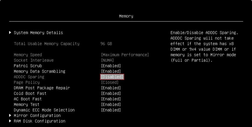
Figure 4. Disable ADDDC Sparing in UEFI SettingsWhen ADDDC Sparing is set to Enabled, both Full Mirroring and Partial Mirroring setup options get grayed out and mirroring feature cannot be enabled as shown in the following figure.
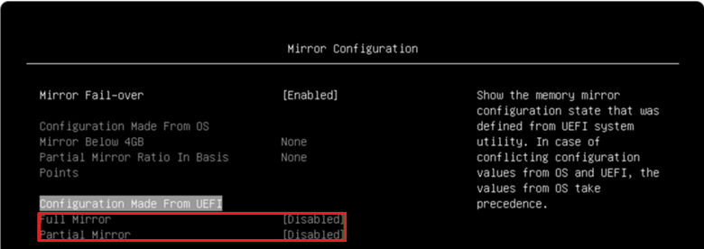
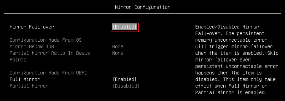
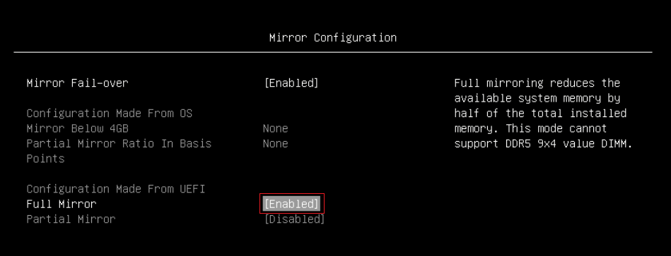
Figure 5. Full Mirror and Partial Mirror cannot be enabled when ADDDC is enabled - Go to System Settings > Memory > Mirror Configuration page, you can set Mirror Fail-over for Mirror Configuration. When Mirror Fail-over is Enabled, a persistent memory uncorrectable error will trigger mirror failover. When Mirror Fail-over is disabled, Lenovo UEFI will skip the mirror failover even when a persistent uncorrectable error occurs. The default setting of Mirror Fail-over is Enabled as shown in the following figure.
- On System Settings > Memory > Mirror Configuration page, enable Full Mirror as shown in the figure below.
- Save Settings and reboot host to make full mirror configuration take effect.
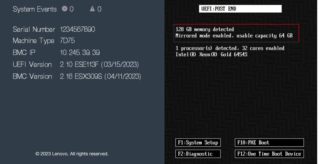
- After configured Full Mirror in UEFI settings, the splash screen displays a total of 128 GB memory detected, Mirrored mode enabled, usable capacity 64 GB as shown in the figure below.
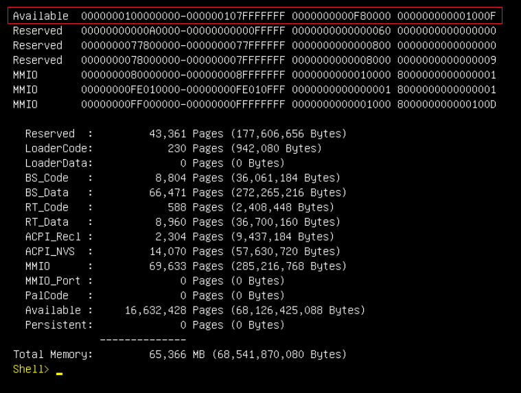
- Check Memory Map under EFI shell. The current memory map can be shown via the memmap If the full mirror mode is enabled, the memory map will be changed with mirrored size reduction. The top memory address is 0X207fffffff (130 GB) in independent mode as shown in Figure 9, and the top memory address is 0x107fffffff (66 GB) in full mirror mode as shown in Figure 10. As there’s a 2GB MMIO size under 4GB address space, the memory size in independent mode is 128 GB (130 GB – 2 GB) and memory size in full mirror mode is 64 GB (66 GB – 2 GB).

Server UEFI settings for Address Range Mirroring
In UEFI, Address Range Mirroring is referred to as Partial Mirror. It reduces the available system memory by percentage of up to 50% per processor. The percentage is set by the Partial Mirror Ratio In Basis Points setting.
When memory is configured in Partial Mirror mode which is also called Address Range Mirroring, a subset of memory is mirrored and the rest of the memory in non-mirrored mode. Address Range Mirroring allows greater granularity in selecting how much memory is dedicated for redundancy.
Address Range Mirroring requires a firmware-OS interface for a user to specify the desired subset of memory to mirror. Currently Lenovo UEFI settings provides options for user to configure partial mirroring configuration and we don't have an ESXi based tool to configure partial mirroring configuration from OS side.
The following are steps for configuring Address Range Mirroring in UEFI Settings on the ThinkSystem SR650 V3:
- Configure Adaptive Double Device Data Correction (ADDDC) Sparing as described in the Server UEFI settings for Memory Mirroring section.
- Configure Mirror Fail-over as described in the Server UEFI settings for Memory Mirroring section.
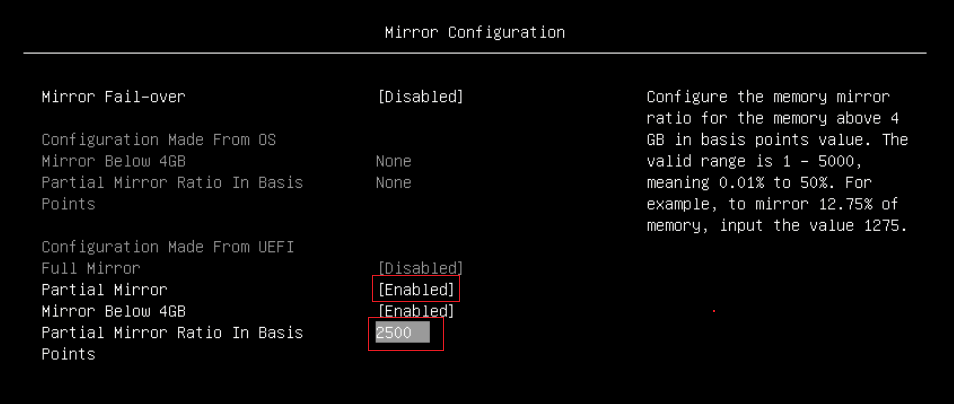
- Go to the System Settings > Memory > Mirror Configuration page, do the following, as shown in the figure below.
- Enable Partial Mirror
- Enable or disable Mirror Below 4G. You can choose enable or disable "Mirror Below 4G" for Partial Mirror. When "Mirror Below 4G" is enabled, all available system memory below the 4GB address limit will be mirrored. When "Mirror Below 4G" is disabled, all available system memory below the 4GB address limit won't be mirrored.
- Input Partial Mirror Ratio in Basis Points. This option is used for percentage setting of memory mirror for each processor. For example, to mirror 12.75% of memory, input the value 1275; to mirror 25% of memory, input the value 2500.
- Save Settings
- Reboot the host so that the partial mirror configuration takes effect.
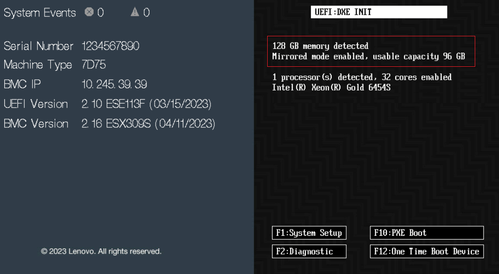
- Check if mirrored mode is enabled on POST (Power On Self Test) stage, and the message “Mirrored mode enabled, usable capacity xx GB” is expected on POST page. The system has a total of 128 GB memory detected, mirror 25% of memory, and the usable capacity is 96 GB as shown below.
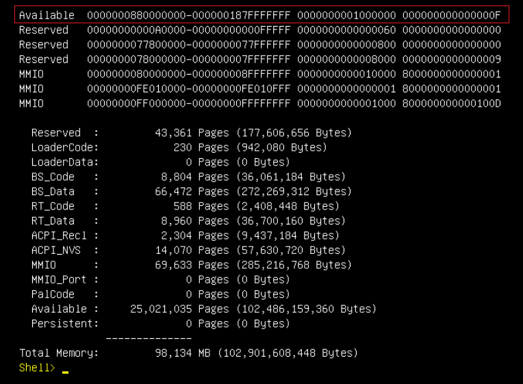
- Check Memory Map under EFI shell, and the current memory map can be shown via the memmap If memory in independent mode, the top memory address is 0X207fffffff (130 GB) as shown in Figure 9. If memory is in Address Range Mirroring mode and mirrored 25% of memory, the top memory address is 0x187fffffff (98 GB) as shown in the figure below. As there’s a 2GB MMIO size under 4GB address space, the memory size in independent mode is 128 GB (130 GB - 2 GB) and memory size in Address Range Mirroring mode is 96 GB (98 GB - 2 GB).
Configuring VMware ESXi for mirroring
vSphere ESXi supports both Memory Mirroring and Address Range Mirroring features. Memory scheduler puts the memory pages consumed by critical services on reliable memory regions to provide highly reliable when memory occurred uncorrectable fault. It’s worth noting that more than the kernel can use this feature. We can also configure VM to place the memory pages consumed by VM on reliable memory area to protect the VMs from memory failure.
The following are steps for using reliable memory in ESXi on the ThinkSystem SR650 V3:
- SSH to ESXi and run the following ESXCLI command to check reliable memory after configuring Memory Mirroring or Address Range Mirroring in UEFI settings.
~# esxcli hardware memory get
~# vsish -e get /memory/comprehensive
The following figure shows reliable memory in ESXi when memory is configured in Memory Mirroring mode.
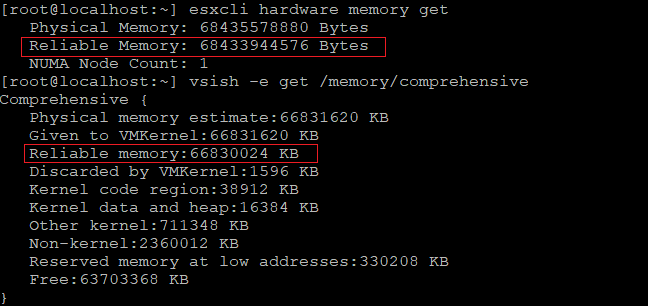
Figure 14. Check full mirror memory in ESXiThe following figure shows reliable memory in ESXi when memory is configured in Address Range Mirroring mode and mirrored 25% of memory.
- We can inject an uncorrectable error (UCE) within mirroring range to verify the memory mirroring feature. If an UCE within mirroring range can be treated as a corrected error (CE) and ESXi keep on running, the test passes. If not, the test fails.
ESXi Beta build required: Error injection testing requires ESX beta build type as the error injection capabilities are enabled in only ESXi beta build type.
ESXi provides a vmkernel module mceInjACPI which can be used to inject UCE via VSI interface and use ACPI standard EINJ defined interface. We need to install the einj test vib for the corresponding ESXi build and then you can use mceInjACPI kernel module for error injection.
- Run the following commands to install the einj test vib on ESXi as shown in the figure below.
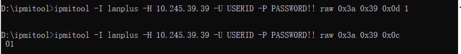
~# esxcli software vib install -v - In order to test error injection, we need to enable Direct Connect Interface (DCI) for Lenovo ThinkSystem servers due to security policy. Please note that only internal error injection testing requires to enable DCI. Run the following IPMI commands to enable DCI and get DCI status as shown in the figure below.
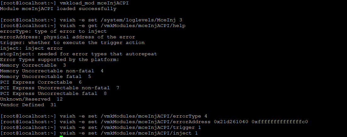
~# ipmitool -I lanplus -H BMC_IP -U USERID -P PASSW0RD raw 0x3a 0x39 0x0d 1 ~# ipmitool -I lanplus -H BMC_IP -U USERID -P PASSW0RD raw 0x3a 0x39 0x0c - Run the following commands to inject an UCE to mirroring range on beta type ESXi as shown in the figure below. We can refer to memmap in Figure 10 or Figure 13 to select a mirroring memory address or non-mirroring address for error injection.
~# vmkload_mod mceInjACPI ~# vsish -e set /system/loglevels/MceInj 3 ~# vsish -e get /vmkModules/mceInjACPI/help ~# vsish -e set /vmkModules/mceInjACPI/errorType 4 ~# vsish -e set /vmkModules/mceInjACPI/errorAddress 0x21d261040 0xffffffffffffffc0 ~# vsish -e set /vmkModules/mceInjACPI/trigger 1 ~# vsish -e set /vmkModules/mceInjACPI/inject 1 - Check vmkernel.log to see if UCE can be downgraded to CE and check if ESXi keep on running, and see the vmkernel log as shown in the following figure:
- To compare the UCE injection to mirroring range, we can inject an UCE to non-mirroring address range as shown in following figure.

Figure 20. Inject UCE to non-mirrored rangeThe memory controller detects the UCE and then triggers machine check exception (MCE) to ESXi, and system will run into purple screen of death (PSOD) as shown in following figure.
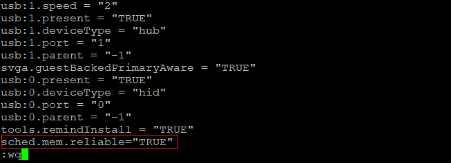
- We can configure VM to place the memory pages consumed by VM on reliable memory area to protect the VMs from memory failure.
Create a VM on ESXi and edit the .vmx file to configure reliable memory for the VM. The .vmx file is typically located in the directory where you created the virtual machine. You can also run command find / -name "*.vmx" on ESXi to get the location of the .vmx file.
- Power off the VM, edit the .vmx file and add the following parameter and then save the settings, as shown in figure below.
sched.mem.reliable = "TRUE" - Power on VM, then memory pages consumed by virtual machines will be on reliable memory area.


References
For additional information, see the following:
- Address Range Partial Memory Mirroring
https://www.intel.com/content/www/us/en/developer/articles/technical/address-range-partial-memory-mirroring.html - vSphere Reliable Memory
https://docs.vmware.com/en/VMware-vSphere/8.0/vsphere-resource-management/GUID-5639BA75-E1C0-4137-BB77-20829E673740.html
Author
Chengcheng Peng is a VMware Engineer in the Lenovo Infrastructure Solutions Group in Beijing, China. As a VMware engineer with 6 years’ experience, she mainly focuses on vSphere security and storage.
Thanks to the following people for their contributions to this project:
- Boyong Li, Lenovo OS Technical Leader
- Skyler Xing12 Zhang, Lenovo VMware Engineer
- Alpus Chen, Lenovo VMware Engineer
- David Hsia, Lenovo VMware Engineer
- Chia-Yu Chu, Lenovo VMware Engineer
- Gary Cudak, OS Architect and WW Technical Lead
- David Watts, Lenovo Press
Trademarks
Lenovo and the Lenovo logo are trademarks or registered trademarks of Lenovo in the United States, other countries, or both. A current list of Lenovo trademarks is available on the Web at https://www.lenovo.com/us/en/legal/copytrade/.
The following terms are trademarks of Lenovo in the United States, other countries, or both:
Lenovo®
ThinkSystem®
The following terms are trademarks of other companies:
Intel®, the Intel logo and Xeon® are trademarks of Intel Corporation or its subsidiaries.
Other company, product, or service names may be trademarks or service marks of others.
Configure and Buy
Please select a locale
Full Change History
Course Detail
Employees Only Content
The content in this document with a is only visible to employees who are logged in. Logon using your Lenovo ITcode and password via Lenovo single-signon (SSO).
The author of the document has determined that this content is classified as Lenovo Internal and should not be normally be made available to people who are not employees or contractors. This includes partners, customers, and competitors. The reasons may vary and you should reach out to the authors of the document for clarification, if needed. Be cautious about sharing this content with others as it may contain sensitive information.
Any visitor to the Lenovo Press web site who is not logged on will not be able to see this employee-only content. This content is excluded from search engine indexes and will not appear in any search results.
For all users, including logged-in employees, this employee-only content does not appear in the PDF version of this document.
This functionality is cookie based. The web site will normally remember your login state between browser sessions, however, if you clear cookies at the end of a session or work in an Incognito/Private browser window, then you will need to log in each time.
If you have any questions about this feature of the Lenovo Press web, please email David Watts at dwatts@lenovo.com.


