

Top
Author
Published
5 Mar 2025Form Number
LP2176PDF size
10 pages, 345 KBSubscribed to LP2176.
Thank you for your feedback.
Abstract
This paper provides a detailed guide for interpreting and diagnosing Machine Check Exception (MCE) outputs in the VMware ESXi. It explains the structure of MCE logs, including various registers, error codes, and status bits, and describes how to map these data points to potential hardware issues such as CPU faults, memory errors, or system bus problems. The paper outlines a step-by-step approach for decoding error information, offers troubleshooting strategies, and recommends best practices for collecting additional diagnostic data to facilitate effective remediation.
This paper is for system administrators and technical support personnel who need to efficiently identify and resolve critical hardware errors on Lenovo Servers.
Introduction
VMware ESXi PSOD stands for Purple Screen of Diagnostics (also known as Purple Screen of Death). The name is derived from Microsoft Windows stop error screen, known as the Blue Screen of Death. The diagnostics screen appears when VMware ESXi kernel detects a fatal error.
Intel and AMD implement Machine-Check Architecture (MCA) that detects and reports hardware issues, including system bus errors, RAM (ECC and parity) errors, and other CPU-related faults.
MCE is a critical error that occurs when a computer’s processor detects when it identifies a serious hardware fault. These exceptions are typically caused by memory corruption, CPU cache failures, or other hardware faults. There are a set of model-specific registers (MSRs) that are used to report errors. When a hardware error occurs, global and bank-specific status machine-check architecture registers are populated with information regarding the cause, and whether the CPU can safely continue execution. In the case of a correctable error, ESXi logs the incident and register contents in the VMkernel logs. If an error is uncorrectable, and the CPU cannot continue safely, ESXi halts with a purple diagnostic screen.
An example PSOD message is shown in the following figure.

To diagnose the issue, capture a screenshot of the PSOD screen. Then, reboot the system, and collect the logs.
Machine-Check Architecture Registers
Machine-Check Architecture (MCA) Registers are part of Intel's system used to log machine-check errors. These specialized hardware registers that collect error information when a MCE occurs. Key registers include MCI_STATUS, MCi_ADDR, and MCi_MISC registers, which provide insights into the type and location of hardware errors. The global MCA register (MCG_STATUS) reports whether an MCE is in progress.
The log message consists of one line for each relevant bank and includes the physical detail such as
- The physical CPU number
- The text "MCA:" label
- The error class
- How the error was reported
- The MCG_STATUS register (G)
- The bank number (B)
- The MCi_STATUS register (S)
- The MCi_ADDR register (A)
- The MCi_MISC register (M)
- The decoded system physical address and size (P) (applicable in 6.7 and later)
- A human-readable interpretation of the error.
Example Logs:
cpu…)MCA:…: UC Excp G5 B3 Sbe00000000080189 A8e70096740 Mb07485 Cache Hierarchy: Level 1 Cache Snoop Error. cpu…)MCA:…: SRAR Excp Gf B1 Sbd80000000100134 Aa83bf95200 M86 Pa83bf95200/40 Cache Hierarchy: Level 0 Data Cache DataRead Error.
Error Classes:
- UC: Uncorrected, unrecoverable
- SRAR: Uncorrected, recoverable, action required (Intel)
- SRAO: Uncorrected, recoverable, action optional (Intel)
- UCNA: Uncorrected, no action required (Intel)
- UCR: Uncorrected, recoverable (AMD)
- CE: Corrected
- DE: Deferred (AMD)
Error Reporting Methods:
- Init: Found during boot-time initialization (possibly from prior to the reboot)
- Poll: Periodic polling of the MCA banks
- Excp: MCE handler
- Intr: Corrected Machine Check Interrupt handler
Automatic Interpretation
VMware ESXi attempts to interpret status register contents for display in the log and the purple diagnostic screen. For example:
- Cache Hierarchy: Level 0 Data Cache Read Error.
- Bus error, node originated, read, memory access
In this section:
Decoding the global MCA status (MCG_STATUS) register
The MCG_STATUS register plays a crucial role in Intel’s Machine Check Architecture (MCA) by providing a high-level summary of the processor’s state after a machine-check exception (MCE) occurs. This 64-bit register helps determine whether execution can safely resume and whether the recorded error is directly tied to the instruction pointer.
This section explains the significance of these bits and provides an example analysis of how to interpret the register’s value during an error event.
The following figure illustrates the structure of the MCG_STATUS register, but only the lower 4 bits are defined, each serving a specific diagnostic purpose. These bits indicate whether execution can restart, if an error is linked to the instruction pointer, and whether an MCE has been recorded.

Figure 2. MCG_STATUS Register (from Intel)
The global status register is 64-bit, but only the low 4 bits have meaning:
- Bit 0 (RIPV) — Indicates that execution can restart reliably
- Bit 1 (EIPV) — Indicates that the instruction pointer is associated with the error.
- Bit 2 (MCIP) — Indicates an MCE was generated
- Bit 3 (LMCE_S) — Indicates a local MCE.
Example Analysis:
cpu…)MCA: … : UC Excp G5 B3 Sbe00000000080189 A8e70096740 Mb07485 Cache Hierarchy: Level 1 Cache Snoop Error.
If the global status register value is "5" (0101 in binary), this indicates to:
- LMCE_S=0
- MCIP=1
- EIPV=0
- RIPV=1
This indicates a machine check is in progress, and the Restart IP is valid.
Manual Decoding of MCi_STATUS register
The MCi_STATUS register is a 64-bit model-specific register (MSR) that provides detailed error reporting when a machine-check exception (MCE) occurs. This register helps diagnose hardware failures by indicating the validity, severity, and source of detected errors
This section explains the significance of each field within the MCi_STATUS register and how they contribute to system debugging and error handling.
The following figure illustrates the structure of the MCi_STATUS register, where the high-order bits (57:63) summarize the processor state and provide key diagnostic information, such as whether the error is uncorrectable, if multiple errors have occurred, and whether the processor state may be corrupted. Additionally, the lower bits contain error codes that can be used to further analyze the nature of the fault.
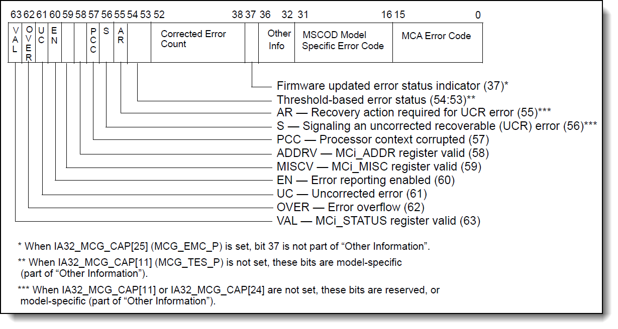
Figure 3. MCi_STATUS Register (from Intel)
The MCi_STATUS register (64 bits) provides additional error details. The high-order bits (57:63) summarize the processor state:
- Bit 63 (VAL): Indicates that the register contains valid data.
- Bit 62 (OVER): Indicates multiple errors occurred before reporting.
- Bit 61 (UC): Uncorrectable error.
- Bit 60 (EN): Error reporting was enabled.
- Bit 59 (MISCV): Miscellaneous register contains valid data.
- Bit 58 (ADDRV): Address register contains valid data.
- Bit 57 (PCC): Processor state may be corrupted.
- Bits 56:32: contain other information, which may be reserved, used for counters, or hold other information that is model-specific. For more information, see the vendor documentation listed in the reference of this article
- Bits 31:16 contain a model-specific extended error code. For more information, see the vendor documentation listed in the reference of this article
- Bits 15:0: contains the machine-check architecture-defined error code for the machine-check error condition detected.
Machine-check architecture-defined error codes
The lower 16 bits (0:15) define several errors, categorized into Simple and Compound error codes.
Option 1: Using Automatic Tool
You can debug the error efficiently using the following tool which automates the steps below:
https://vmware-psod-reader.github.io/vmware-psod-reader/
Option 2: Using Manual Steps
The manual steps refer to the process of manually decoding machine-check architecture (MCA) error codes by interpreting their binary encoding. This method is useful when automated tools are unavailable, allowing engineers and system administrators to directly diagnose hardware failures from the MCi_STATUS register values.
MCA error codes help identify various types of processor and memory-related errors. These errors can be categorized into simple errors and compound errors, as shown in the two tables below.
The list below describes the encoding of the placeholder fields (such as {MMM}, {CCCC}, {TT}, {LL}, {RRRR}, {PP}, and {II}) in the Table 2.
- Encoding of Transaction Type (TT) sub-field:
- 00 – Instruction
- 01 – Data
- 10 – Generic
- 11 – Reserved
- Encoding of Memory Hierarchy Level (LL) sub-field:
- 00 – Level 0
- 01 – Level 1
- 10 – Level 2
- 11 – Generic
- Encoding of memory transaction type (MMM) sub-field:
- 000 – Generic undefined request
- 001 – Memory read error
- 010 – Memory write error.
- 011 – Address or command error.
- 100 – Memory scrubbing error.
- 101-111 – Reserved.
- Encoding of channel number (CCCC) sub-field:
- 0000-1110 – Channel number.
- 1111 – Channel not specified.
- Encoding of Request (RRRR) sub-field:
- 0000 – Generic error
- 0001 – Generic read
- 0010 – Generic write
- 0011 – Data read
- 0100 – Data write
- 0101 – Instruction fetch
- 0110 – Prefetch
- 0111 – Evict
- 1000 – Snoop (probe)
- Encoding of Participation Processor (PP) sub-field:
- 00 – Local node originated the request.
- 01 – Local node responded to the request.
- 10 – Local node observed error as third-party.
- 11 – Generic
- Encoding of Timeout (T) sub-field:
- 0 – Request did not timeout.
- 1 – Request did timeout.
- Encoding of Memory/IO (II) sub-field:
- 00 – Memory access
- 01 – Reserved
- 10 – I/O
- 11 – Other
Example Analysis of an MCE PSOD
The figure below is an example PSOD screen, illustrating how an error is reported when a failure is detected in the memory controller. By converting the MCi_STATUS register value to binary and analyzing its lower bits, we can determine the specific error type and affected hardware component.
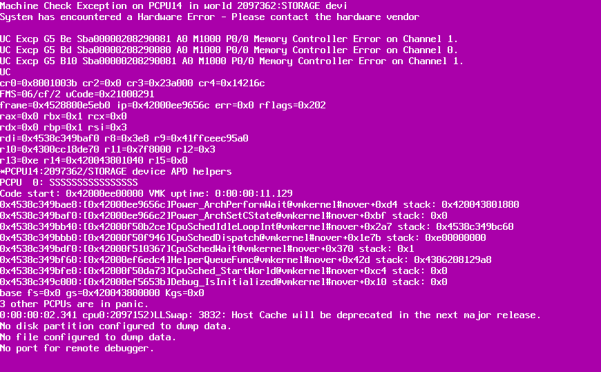
Given an MCi_STATUS register value of 0xba00000288290081. Convert it to binary:
1011 1010 0000 0000 0000 0000 0000 0010 0000 1000 0010 1001 0000 0000 1000 0001
Extracting the lower 16 bits (0000 0000 1000 0001), we identify:
- Memory controller errors
- Generic undefined request
- Channel 1 error
VMware's PSOD screen would show: "Memory Controller Error on Channel 1”
After replacing the processor with an embedded memory controller, the issue was resolved
Reference
For more information, see these resources:
- Intel - Chapters 17 and 18 of the Intel 64 and IA-32 Architectures Software Developer’s Manual:
https://cdrdv2.intel.com/v1/dl/getContent/671200 - AMD - Chapter 9 of the AMD64 Architecture Programmer’s Manual, Volume 2: System Programming:
https://docs.amd.com/v/u/en-US/24593_3.43 - VMware KB, Decoding Machine Check Error (MCE) output after an ESXi panic (Purple Screen):
https://knowledge.broadcom.com/external/article/367928/decoding-machine-check-error-mce-output.html - Nutanix KB, Debugging ESX Machine Check Exception (MCE) PSOD:
https://portal.nutanix.com/page/documents/kbs/details?targetId=kA0600000008gYECAY
Author
David Hsia is an OS Engineer in the Lenovo Infrastructure Solutions Group, based in Taipei, Taiwan. As a specialist in Linux and VMware technical support, he is interested in operating system and focuses on VMware vSphere and ESXi.
Thanks to the following specialists for their contributions and suggestions:
- Chengcheng Peng, Lenovo VMware Engineer
- Alpus Chen, Lenovo VMware Engineer
- Skyler Xing12 Zhang, Lenovo VMware Engineer
- David Watts, Lenovo Press Senior Manager
Trademarks
Lenovo and the Lenovo logo are trademarks or registered trademarks of Lenovo in the United States, other countries, or both. A current list of Lenovo trademarks is available on the Web at https://www.lenovo.com/us/en/legal/copytrade/.
The following terms are trademarks of Lenovo in the United States, other countries, or both:
Lenovo®
The following terms are trademarks of other companies:
AMD is a trademark of Advanced Micro Devices, Inc.
Intel®, the Intel logo is a trademark of Intel Corporation or its subsidiaries.
Microsoft and Windows are trademarks of Microsoft Corporation in the United States, other countries, or both.
Other company, product, or service names may be trademarks or service marks of others.
Configure and Buy
Please select a locale
Full Change History
Course Detail
Employees Only Content
The content in this document with a is only visible to employees who are logged in. Logon using your Lenovo ITcode and password via Lenovo single-signon (SSO).
The author of the document has determined that this content is classified as Lenovo Internal and should not be normally be made available to people who are not employees or contractors. This includes partners, customers, and competitors. The reasons may vary and you should reach out to the authors of the document for clarification, if needed. Be cautious about sharing this content with others as it may contain sensitive information.
Any visitor to the Lenovo Press web site who is not logged on will not be able to see this employee-only content. This content is excluded from search engine indexes and will not appear in any search results.
For all users, including logged-in employees, this employee-only content does not appear in the PDF version of this document.
This functionality is cookie based. The web site will normally remember your login state between browser sessions, however, if you clear cookies at the end of a session or work in an Incognito/Private browser window, then you will need to log in each time.
If you have any questions about this feature of the Lenovo Press web, please email David Watts at dwatts@lenovo.com.


