Abstract
The IBM eServer BladeCenter is considered by many to just be for Intel processor-based servers. It is more appropriate, however, to consider it a platform device, capable of housing combinations of two-way (HS20) and four-way (HS40) Intel processor-based servers, as well as two-way (JS20) PowerPC 970 processor-based servers. In fact, you should consider BladeCenter to be an infrastructure platform, because of the multitude of devices which can be installed and configured in a single BladeCenter, or in a combination of BladeCenter systems. As a result, BladeCenter configurations can often be very complex. There are, however, several elements that are common to many solutions, thereby simplifying the planning and installation phases of a BladeCenter deployment.
This document has been created for technical staff engaged in solution design and implementation of BladeCenter. This document is intended to provide a technical summary of several configuration issues, which are consistent across many BladeCenter installations.
Main

Default BladeCenter configuration
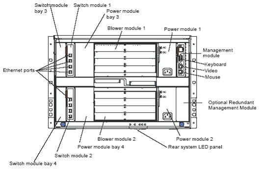
Note: In this document, the term blade refers to any device which occupies a bay in the front of a BladeCenter, and the term module defines any device which occupies bays in the rear of a BladeCenter.
The Management Module (MM) and the devices installed in the module bays are configured, by default, to request an IP address from a DHCP server. If no IP addresses are assigned to the devices configured, they are configured automatically with the following IP addresses:
Management Module:
- External port: 192.168.70.125
- Internal Port: 192.168.70.126
Devices in module bays:
- Module bay 1: 192.168.70.127
- Module bay 2: 192.168.70.128
- Module bay 3: 192.168.70.129
- Module bay 4: 192.168.70.130
Power considerations
With the default power supply configuration, power supplies 1 and 2, are in power domain A, and power supplies 3 and 4 are in power domain B. Power domain A supplies power to all modules and blade slots 1 to 6. Power domain B supplies power to blade slots 7 to 14 only.
Power supply 1 and power supply 2 must have separate AC sources to be in a redundant, supported configuration. Power redundancy is achieved for the entire BladeCenter by having two AC sources, with each AC source connected in both power domains.
In other words:
- AC source 1 is connected to power supplies 1 and 3
- AC source 2 is connected to power supplies 2 and 4
Cisco Intelligent Gigabit Ethernet Switch Module(CIGESM) considerations
- Do not confuse trunking and port aggregation.
- Consider the CIGESM as an EDGE device, and the corresponding upstream switch as a CORE device.
- Change the switch IP address only from the Web interface of the Management Module.
- Define the default gateway on the switches; do not leave the field blank.
- Blades and Management network must be on different subnets.
- Configure at least one external port on each CIGESM for trunking.
- Port aggregation will only be required based upon user data traffic demands.
Default Vlan configuration of CIGESM
Vlan1 Management Vlan
- Trunking is disabled in hardware.
- Changing the management Vlan is not recommended.
- Blade NICs are on this VLAN
- This will need to be modified to correspond to the specific customer network infrastructure design.
IBM Director Server considerations
- The IBM Director management server must have IP connectivity to the Blade NICs.
- The IBM Director management server must have IP connectivity to the Management Module.
- In a Cisco environment, this is accomplished by modifying the appropriate routing table(s).
Remote Deployment Manager Server considerations
- The RDM image repository is not portable. Ensure enough drive space is available to store images, where RDM is being installed.
- The repository must be installed in the RDMROOT.
- RDM does not use NetBIOS, so the RDMROOT must be installed on DASD of the IBM Director Server. For purposes of this document, DASD is considered to be all local Disk visible to the OS, including SAN attached Drives.
RDM/PXE/DHCP configuration considerations
- DHCP Option 60 needs to be added to DHCP server only if the DHCP server is installed on the same server as the RDM server.
- The subnet on which the blades reside must be served by a DHCP server, as well as the RDM/PXE server. The DHCP scope for the Blade subnet must have a router defined (Option 3). This is required even on a flat network where there is no actual router. If there is no actual router, use the RDM server's address for the router specification.
- There can be only one PXE server on a subnet. If you want to use RDM, any and all other PXE servers on the same subnet as the Blades must be turned off.
For more information
Please refer to the product documentation for more detailed instructions.
Trademarks
Lenovo and the Lenovo logo are trademarks or registered trademarks of Lenovo in the United States, other countries, or both. A current list of Lenovo trademarks is available on the Web at https://www.lenovo.com/us/en/legal/copytrade/.
The following terms are trademarks of Lenovo in the United States, other countries, or both:
Lenovo®
BladeCenter®
The following terms are trademarks of other companies:
Intel®, the Intel logo is a trademark of Intel Corporation or its subsidiaries.
IBM® is a trademark of IBM in the United States, other countries, or both.
Other company, product, or service names may be trademarks or service marks of others.
