Abstract
The QLogic 20-port and 10-port 4 Gb SAN Switch Modules enable high performance 4 Gb Fibre Channel SAN solutions, and allow BladeCenter integration with any open-standards-based storage area networks utilizing full fabric switching functionality. These two switches have almost the same features and functions except for the number of activated ports: the 10-port switch has ten activated ports, and the 20-port switch has 20 activated ports.
Introduction
The QLogic 20-port and 10-port 4 Gb SAN Switch Modules enable high performance 4 Gb Fibre Channel SAN solutions, and allow BladeCenter integration with any open-standards-based storage area networks utilizing full fabric switching functionality. These two switches have almost the same features and functions except for the number of activated ports: the 10-port switch has 10 activated ports and the 20-port switch has 20 activated ports.
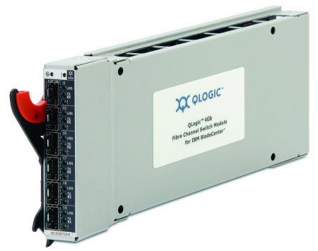
Figure 1 shows the QLogic 4 Gb SAN Switch Module.

Figure 1. QLogic 4 Gb SAN Switch Module for BladeCenter
Did you know?
The switch connects to the midplane directly, without having to use cables or small form-factor pluggable (SFP) modules. By eliminating these components for up to 14 servers, the resulting savings alone cover the BladeCenter chassis investment.
The module is licensed to operate in either full-fabric mode or intelligent pass-thru mode. The module allows BladeCenter integration with any open-standards-based SAN, whether it is an enterprise open-system fabric functionality using the full-fabric mode or the module with transparent switching functionality using the intelligent pass-thru mode.
Part number information
Table 1 shows the part number to order this module.
Table 1. Part number and feature code for ordering
| Description | Part number | Feature code |
| QLogic 20-port 4 Gb SAN Switch Module for BladeCenter | 43W6725 | 2987 |
| QLogic 10-port 4 Gb SAN Switch Module for BladeCenter | 43W6724 | 2986 |
The part number includes the following items:
- One QLogic 20-Port or 10-Port 4 Gb SAN Switch Module for BladeCenter
- The Documentation CD
- The IBM Important Notices document
The switches come without small form-factor pluggable (SFP) transceivers, which must be ordered additionally. Table 2 lists the part numbers that are supported.
Table 2. Supported SFPs for the QLogic 4 Gb SAN Switch Module
| Description | Part number | Feature code |
| 4 Gbps SW SFP Transceiver | 39R6475 | 4804 |
| 4 Gbps shortwave SFP Transceiver pair | 26K7941 | 2410 |
| 4 Gbps 4 km longwave SFP Transceiver | 23R1703 | Not available |
| 4 Gbps 4 km longwave SFP Transceiver 4 pack | 23R1704 | Not available |
| 4 Gbps SW SFP Transceiver 4 Pack | 22R4897 | Not available |
| 4 Gbps SW SFP Transceiver | 22R4902 | Not available |
Features
The QLogic 4 Gb SAN Switch Modules have the following features:
- Six external autosensing (1, 2, or 4 Gbps) Fibre Channel ports that operate at a maximum of 4 Gbps
- 14 internal Fibre Channel ports that operate at a maximum of 4 Gbps
- Two internal full-duplex 100 Mbps Ethernet interfaces
- External ports that can be configured as F_ports (fabric ports), FL_ports (fabric loop ports), or E_ports (expansion ports)
- Internal ports that are configured as F_ports at 2 Gbps or 4 Gbps
- Power-on diagnostics and status reporting
- Fabric security for controlling management access (optional feature)
- Support for Non-Disruptive Code Load Activation (NDCLA)
- Registered State Change Notification (RSCN)
- Support for standards-based FC-SW2 interoperability
- Error detection
- Frame bundling
- Configurable Fabric Address Notification (FAN)
- Support for up to 239 switches depending on configuration
The following software features come with the switch module:
- QuickTools Web interface
- 20-port licensing (20-port version only)
- 10-port licensing (10-port version only)
The switch supports the following fabric management (all management connections go through the management module):
- Management methods:
- Web interface through QuickTools
- Command-line interface (CLI) through Telnet program
- Enterprise Fabric Suite 2007 application (for customers that already use this tool)
- Switch simple network management protocol (SNMP) agent: enables a network management workstation to receive configuration values, traffic information, and Fibre Channel failure data through SNMP and the Ethernet interface
For the QLogic 10-Port 4 Gb SAN Switch Module, the default port license assignments are 1 through 7 for internal ports (the first seven blade bays), and 0, 15, and 16 for external ports (the first three external ports - see Figure 4). Port license assignments can be changed to other available internal ports (8 through 14) or external ports (17, 18, or 19) by using the QLogic management tools.
Supported BladeCenter chassis and expansion cards
The QLogic 4 Gb SAN Switch Modules are supported in the BladeCenter chassis as listed in Table 3.
Table 3. BladeCenter chassis that support the QLogic 4 Gb SAN Switch Modules
| QLogic 20-port 4 Gb SAN Switch Module for BladeCenter | 43W6725 |
N
|
Y
|
Y
|
Y**
|
Y†
|
Y
|
Y‡
|
| QLogic 10-port 4 Gb SAN Switch Module for BladeCenter | 43W6724 |
Y*
|
Y
|
Y
|
Y**
|
Y†
|
Y
|
Y‡
|
Notes:
* The 10-port 4 Gb SAN Switch Module can be installed in the BladeCenter S; however, by doing so, you lose the ability to connect to the BladeCenter S Disk Storage Modules (DSMs). The Fibre Channel I/O module goes in place of the SAS I/O module that is needed to connect to the DSMs.
** When the I/O module is installed in a BladeCenter T unit, the internal ports operate up to 2 Gbps, and the external ports operate at speeds up to 4 Gbps.
† When the I/O module is installed in standard I/O bays of a BladeCenter HT unit, the internal ports operate up to 2 Gbps, and the external ports operate at speeds up to 4 Gbps.
‡ When the I/O module is installed in an MSIM-HT, the internal ports operate at 4 Gbps, and the external ports operate at 4 Gbps.
The BladeCenter chassis have the following bays:
- BladeCenter S, E, and T have four standard I/O bays (1, 2, 3, and 4)
- BladeCenter H has four standard I/O bays (1, 2, 3, and 4), two bridge bays (5 and 6), and four high-speed bays (7, 8, 9, and 10)
- BladeCenter HT has four standard I/O bays (1, 2, 3, and 4) and four high-speed bays (7, 8, 9, and 10)
The QLogic 4 Gb SAN Switch Modules fit in a standard I/O bay (bays 1-6) and, with the addition of the Multi-Switch Interconnect Module (MSIM) in the BladeCenter H, can also fit in a high-speed I/O bay (bays 7-10). The QLogic 4 Gb SAN Switch Modules are not supported with MSIM-HT in high-speed bays of the BladeCenter HT chassis.
The QLogic 4 Gb SAN Switch Modules support the expansion cards listed in Table 4. Table 4 also lists the chassis bays in which the switch modules must be installed when used with each expansion card.
Table 4. Expansion card support and Chassis I/O bay support
| Supported expansion cards | Part number | ||||||||||
| QLogic 4 Gb SFF FC Expansion Card | 26R0890 | N | N | Y | Y | N | N | N | N | N | N |
| QLogic 4 Gb FC Expansion Card (CFFv) | 41Y8527 | N | N | Y | Y | N | N | N | N | N | N |
| Emulex 4 Gb FC Expansion Card (CFFv) | 43W6859 | N | N | Y | Y | N | N | N | N | N | N |
| QLogic 4 Gb FC Expansion Card (CIOv) | 46M6065 | N | N | Y | Y | N | N | N | N | N | N |
| QLogic 8 Gb FC Expansion Card (CIOv) | 44X1945 | N | N | Y | Y | N | N | N | N | N | N |
| Emulex 8 Gb FC Expansion Card (CIOv) | 46M6140 | N | N | Y | Y | N | N | N | N | N | N |
| QLogic Ethernet and 4 Gb FC Card (CFFh) | 39Y9306 | N | N | N | N | N | N | N | Y | N | Y |
| QLogic Ethernet and 8 Gb FC Card (CFFh) | 44X1940 | N | N | N | N | N | N | N | Y | N | Y |
Note: When the I/O module is installed in a BladeCenter T chassis or in one of the standard I/O bays of a BladeCenter HT unit , the internal ports operate up to 2 Gbps, and the external ports operate at speeds up to 4 Gbps. When the I/O module is installed in an MSIM-HT, the internal ports operate at 4 Gbps and the external ports operate at 4 Gbps.
Popular configurations
The QLogic 4 Gb SAN Switch Modules can be used in various configurations.
Installation in standard switch bays
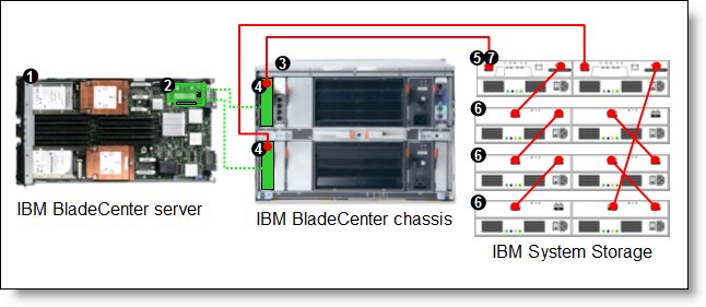
Figure 2 shows the QLogic 20-Port 4 Gb SAN Switch Module installed in standard I/O bays 3 and 4 in a BladeCenter E chassis. The chassis is connected to the IBM System Storage DS3400. The servers in the chassis each have compatible CFFv or CIOv Fibre Channel expansion cards.

Figure 2. BladeCenter connected to an external IBM System Storage DS3400 storage solution
Table 5 lists the parts that are used in this configuration.
Table 5. Components used as shown in Figure 2
| Diagram reference | Part number / Machine type | Description | Quantity |
| Varies | BladeCenter HS22, HS21, or other supported server | 1 to 14 | |
| Varies | Supported CIOv or CFFv expansion card (see Table 4) | 1 per server | |
| Varies | Supported BladeCenter chassis (see Table 3) | 1 | |
| 43W6725 | QLogic 20-Port 4 Gb SAN Switch Module | 1 or 2 | |
| 1726-41X or 1726-42X | IBM System Storage DS3400 (Single or Dual Controller) | 1 | |
| 1727 | Optional IBM System Storage EXP3000 (Single or Dual ESM) | 1 to 3 | |
| Not shown | 39R6536 | DS3000 Partition Expansion License | 1 |
This configuration also requires cabling between the chassis and the storage server and between the storage server and expansion units. (The cable part numbers are not listed in the table.)
Installation in BladeCenter H high-speed switch bays
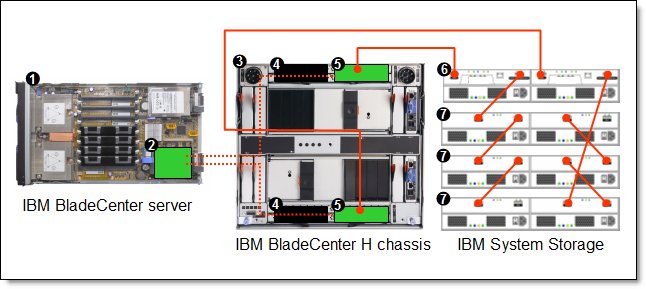
Figure 3 shows the QLogic 20-Port 4 Gb SAN Switch Module installed in MSIMs in the BladeCenter H chassis. The chassis is connected to the IBM System Storage DS3400. The servers in the chassis each have compatible CFFh Fibre Channel expansion cards.

Figure 3. BladeCenter H connected to an external IBM System Storage DS3400 storage solution
Table 6 lists the parts that are used in this configuration.
Table 6. Components used as shown in Figure 3
| Diagram reference | Part number / machine type | Description | Quantity |
| Varies | BladeCenter HS22, HS21, or other supported server | 1 to 14 | |
| Varies | Supported CFFh expansion card (see Table 4) | 1 per server | |
| 8852 | BladeCenter H chassis | 1 | |
| 39Y9314 | Multi-switch Interconnect Module | 1 or 2 | |
| 43W6725 | QLogic 20-Port 4 Gb SAN Switch Module | 1 or 2 | |
| 1726-41X or 1726-42X | IBM System Storage DS3400 (Single or Dual Controller) | 1 | |
| 1727 | Optional: IBM System Storage EXP3000 (Single or Dual ESM) | 1 to 3 | |
| Not shown | 39R6536 | DS3000 Partition Expansion License | 1 |
This configuration also requires cabling between the chassis and the storage server and between the storage server and expansion units. (The cable part numbers are not listed in the table.)
Connectors and LEDs
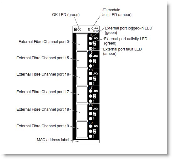
The front panel of the QLogic 4 Gb SAN Switch Module contains the following components, as shown in Figure 4:
- Information LEDs that display the status of the I/O module and its network connections.
- Six external Fibre Channel ports to connect Fibre Channel devices and switches. These ports are labeled 0, 15, 16, 17, 18, and 19 (from top to bottom) on the I/O module.

Figure 4. Front panel of the I/O module
Table 7 lists the LEDs on the front panel and their meanings.
Table 7. LEDs on the front panel
LED name |
LED description |
OK |
This green LED is at the top left of the I/O module on the front panel and indicates that the module is working properly. |
! (I/O module fault) |
This amber LED is at the top right of the I/O module on the front panel. This LED indicates that the I/O module has a fault. If the I/O module fails the POST, this fault LED is lit. |
External port logged-in (LOG) |
There are six green external port logged-in (LOG) LEDs. When one of these LEDs is lit, it indicates that there is a connection (or link) to a device on that port. |
External port activity (TX/RX) |
There are six green external port activity (TX/RX) LEDs. When one of these LEDs flashes, it indicates that data is being received or transmitted (that is, activity is occurring) on that port. The flash frequency is proportional to the amount of traffic on that port. |
External port fault (!) |
There are six amber external port fault (!) LEDs. When an external port fault LED is lit, it indicates that the external port has failed the internal, external, or online port diagnostics tests. |
Operating environment
The environment must meet the following temperature and altitude requirements:
- Operating:
- 10 to 52 °C (50 to 125 °F) at an altitude of 0 to 914 m (0 to 3,000 ft)
- 10 to 49 °C (50 to 20 °F) at an altitude of 0 to 3,000 m (0 to 10,000 ft)
- Non-operating:
- -40 to 65 °C (-40 to 149 °F) at an altitude of 0 to 12,000 m (0 to 39,370 ft)
The environment can have the following humidity levels:
- Operating: 8% to 80%, noncondensing
- Non-operating: 5% to 80%, noncondensing
Related product families
Product families related to this document are the following:
Trademarks
Lenovo and the Lenovo logo are trademarks or registered trademarks of Lenovo in the United States, other countries, or both. A current list of Lenovo trademarks is available on the Web at https://www.lenovo.com/us/en/legal/copytrade/.
The following terms are trademarks of Lenovo in the United States, other countries, or both:
Lenovo®
BladeCenter®
The following terms are trademarks of other companies:
IBM® and ibm.com® are trademarks of IBM in the United States, other countries, or both.
Other company, product, or service names may be trademarks or service marks of others.
