

Top
Authors
Published
16 Aug 2017Form Number
LP0741PDF size
13 pages, 3.3 MBSubscribed to LP0741.
Thank you for your feedback.
Table of Contents
Abstract
In the data center, a server’s usability is very important to support installation, maintenance and upgrade activities. The Lenovo ThinkSystem SR950 provides a high level of usability in the system design. This article highlights the usability features in the SR950 such as, fan replacement, processor and memory access and XClarity management.
Introduction
Lenovo data center systems run many mission critical applications. In datacenters with hundreds to thousands of servers, system maintenance and uptime are critical to business. In order to help ease the burden of installing, servicing, and upgrading systems Lenovo strives to make these tasks as easy as possible by designing in high levels of usability into the systems. Usability that is designed into the server hardware and software can reduce time and cost associated with installing and maintaining systems, and can reduce the chance of errors occurring while working with the system.

Figure 1. Lenovo ThinkSystem SR950
The overall design of the Lenovo ThinkSystem SR950 is based on a modular service model where access is from the front and rear only. This means that nearly all parts can be removed from the front or rear of the system, even parts that are located in the center of the machine (e.g., fans, memory DIMMs, and processors). This design philosophy means the system does not require thick slide rails required to slide the system out for service actions, which maximizes the space inside the chassis for components. This provides more width for the system to increase system density to fit 8 processors in a 4U form factor.
Let’s look at several areas the ThinkSystem SR950 has designed ease of use into the system.
Identifying the SR950 Server
When you contact Lenovo for help, the machine type, model, and serial number information help support technicians to identify your server and provide faster service. The machine type, model number, and serial number, are provided in both text and 2D barcode format on the ID label on the front of the SR950 server.
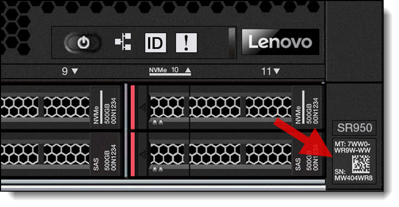
Figure 2. 2D barcode on the front of the server
In addition, at the top rear of the Compute System Tray inside the server, we provide a quick reference (QR) code for mobile access to service information. You can scan the QR code with a mobile device using a QR code reader application and get quick access to the Service Information on the SR950 support web page that provides additional information for parts installation and replacement videos, and error codes for server support.
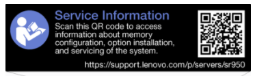
Figure 3. Service label on the server
Fan replacement
The fan design is one of the most unique usability features in the system. Many rack systems have hot-swap fans that allow you to replace fans while the server continues to run. The SR950 process to replace the fans is much quicker and simpler than most servers. Typical rack servers require you to slide the server out from the rack, being careful not to pull out any of the IO cabling from the rear, and lift off the top cover to access the interior of the server. Once inside the server you can replace a fan being careful not to cut your fingers in the process.
The SR950 greatly simplifies the fan replacement process with a very novel design. There is no need to remove or pull-out the SR950 from the rack to replace a fan. Instead you just remove the front bezel and pull on the fan handle. The fan then pivots within its guiding tracks inside the system and then slides out the front of the server. To replace the fan just slide it in the same front slot until it stops and the latch engages, then replace the bezel. This design was key to allowing hot swap fans to be installed between the storage and compute sections of the system.
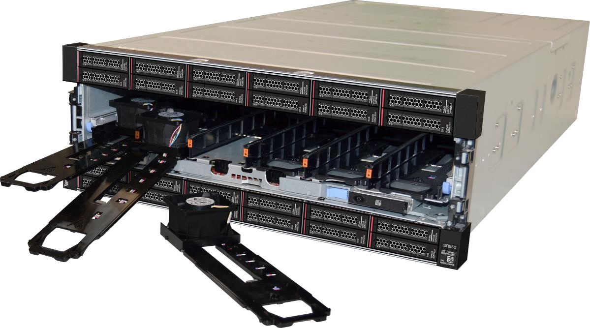
Figure 4. Fans are accessible from the front of the server
Accessing CPUs and memory
On typical rack servers, to access server CPU or memory, you are required to slide the server out from the rack, being careful not to pull out any of the I/O cabling from the rear, and lift off the top cover to access the interior of the server.
With the SR950, you rack the server once and access all components either from the front or rear of the server. To access the CPU or memory, you slide out either the Upper or Lower Compute Tray out the front of the server. At this point you can directly access the top Compute System board which contains 2 CPUs and up to 24 DIMMs. To access the other 2 CPUs and associated DIMMs, you slide out the top Compute Tray which then provides access the lower 2 CPUs and associated DIMMs.
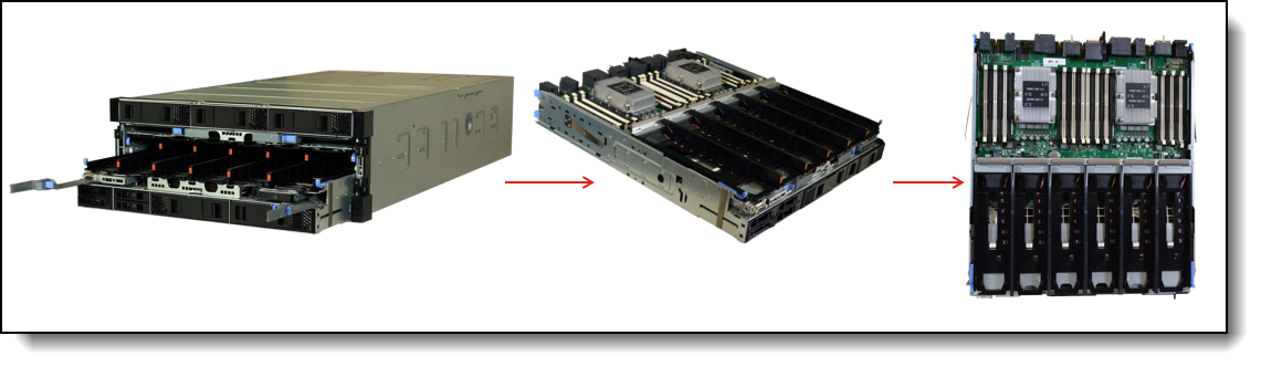
Figure 5. Access to CPUs and memory
Accessing rear I/O
As mentioned above to access interior components on typical rack servers you must first pull the server out of the rack and lift up the top cover. Then, access to the rear IO area typically requires extra reaching and awkward postures while accessing the rear IO area to remove or install adapters.
To access the rear IO (PCIe adapters, LOM, ML2) on the SR950 you pull the IO Tray out the rear of the server with the 2 latching cam handles. From this point all the PCIe adapters, LOM and ML2 cards are easily accessible to replace or add new adapters to empty slots.
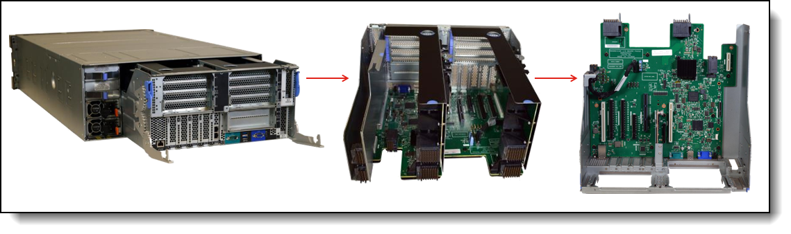
Figure 6. Access to PCIe I/O slots
Front storage
As with most rack systems the front storage devices (HDD, SSD, NVMe) are easily accessed individually from the front of the server by releasing the latch to unlock the drive handle, rotate the handle outward and pull the drive out of the server.
Each SR950 storage backplane supports 4 drives (2x2). You can have up to three backplanes in each Compute Tray (thus 6 backplanes or 24 drives in total). The SR950 supports storage backplanes that support SAS, SATA and NVMe drives in the same 2x2 backplane allowing the flexibility to choose and mix storage types within the same backplane.
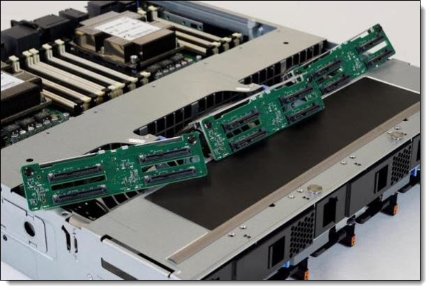
Figure 7. Three of the six drive backplanes
Front Operator Panel & LCD
Most rack servers only have front LEDs that inform you of on/off power status, connection to network or not, and if some type of system error has occurred. You will need to connect a separate device to the server or access the management software online to pull detailed system information in order to know further details about the status of the server.
The SR950 contains not only the typical LEDs for power, network and errors, but also has a LCD panel that provides quick access to system status, firmware, network, and health information. The LCD allows you to scroll up and down to access different menu options.
LCD displays the following type of information:
- System errors such as fan failure, power supply failure, PCI error, etc.
- System VPD information (such as machine type and serial number)
- System firmware levels such as UEFI and XCC code levels
- LXCC network information such as MAC address and IP address
- System environmental information such as temperature, voltage, power consumption
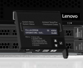
Figure 8. LCD pull-out display panel
The following image shows the LCD display panel menu options flow.
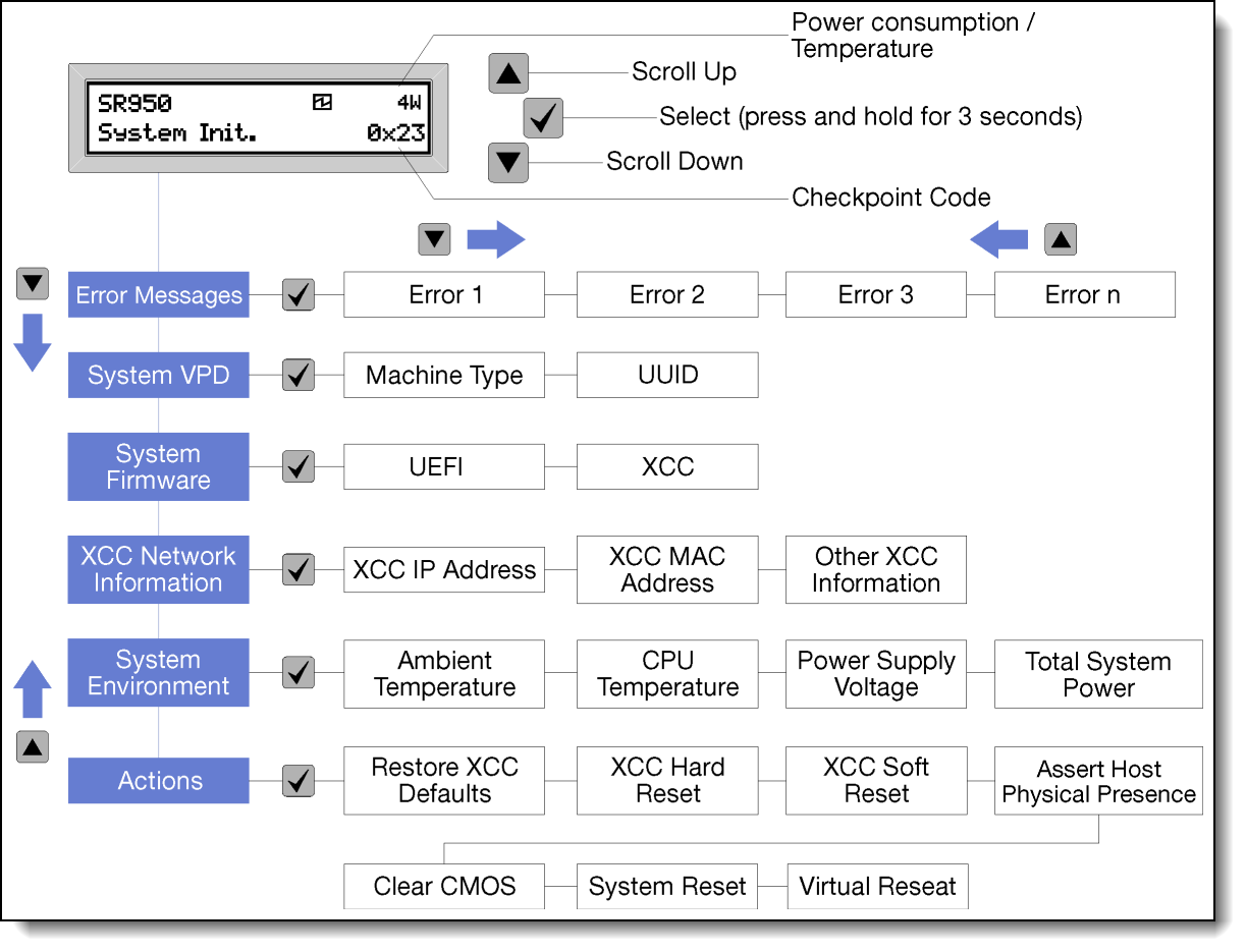
Figure 9. LCD display panel menu structure
Light Path Diagnostics
The SR950 has a unique method to help guide the way to server issues. Light path diagnostics is a system of LEDs on various external and internal components of the server that leads you to the failed component. When an error occurs, LEDs are lit on the front operator panel on the front of the server, then on the failed component. By viewing the LEDs in a particular order, you can often identify the source of the error.
It begins with the Front Operator Panel and LCD that provides quick access to system status, firmware, network and health information (discussed above in further detail).
The SR950 has a unique Light Path Diagnostics on each Compute System Board. Each system board has LEDs that light up to indicate which component is causing the error that was generated. The Light Path LEDs on the system board can even be used when the compute tray is pulled out of the server by pushing the Light Path power button on the compute system board.
Compute System Board LEDs:
- Each Processor (two per system board)
- System board in general
- Each of the 24 DIMM slots
In addition to the front panel/LCD and Compute System Board, the SR950 also has LEDs on the rear of the server. The SR950 has over 20 different LEDS for Power Supplies, PCIe, LOM and IO ports. Power Supplies and Storage drives also have their own error LEDs.

Figure 10. SR950 Compute Board with Light Path Diagnostics button
Lenovo XClarity Administrator
XClarity Administrator is an easy-to-use centralized, resource-management application that simplifies infrastructure management, speeds responses, and enhances the availability of Lenovo server systems and solutions. It runs as a virtual appliance that automates infrastructure tasks for Lenovo infrastructure:
- Discovery and tracking inventory of managed hardware endpoints
- Real-time monitoring and fault handling, such as call home and forwarding events and logs
- Configuration management
- Firmware compliance and updates
- Installation of operating systems and hypervisors
To further increase data center productivity, speed, and precision, XClarity Administrator can be integrated into external management and automation platforms through open REST application programming interfaces (APIs) and XClarity Integrator software plugins. Leveraging a centralized point of integration and running XClarity in external data center platforms helps you focus more on building proficiencies in services and less on resource deployment and management. In addition, you can automate tasks using the PowerShell toolkit or the Python toolkit.
Other XClarity Management Tools
The SR950 supports several XClarity management tools to help manage the server more easily and efficiently.
- Lenovo XClarity Integrators are a suite of software plugins that integrate XClarity Administrator into popular data center applications such as VMware vCenter, Microsoft System Center, and SAP ITOA.
- Lenovo XClarity Energy Manager is a web-based power and temperature management solution designed for data center administrators. It monitors and manages the power consumption and temperature of servers.
- Lenovo XClarity Controller is the embedded management engine in every ThinkSystem server. It delivers an all-new experience through an intuitive, modernized web-based graphical user interface and Redfish-complaint REST APIs.
- XClarity Mobile is the mobile app that can run on a mobile device to help you manage your system while at the system. This can be accessed very easily by connecting a device to one of the USB ports on the front of the system for quick access to more detailed information on the health of the system.
- Lenovo XClarity Provisioning Manager is an all-new, modernized UEFI tool used to configure ThinkSystem servers.
- Lenovo Capacity Planner is a power consumption evaluation tool that enhances data center planning by enabling IT administrators to understand important parameters of different type of racks, servers, and other devices.
Further reading
For further reading, see these resources
This article is one in a series on the ThinkSystem SR950 and SR850 servers:
- Five Highlights of the ThinkSystem SR950
- Five Highlights of the ThinkSystem SR850
- Choosing between Lenovo ThinkSystem SR850 and SR950
- Workloads for 4-Socket and 8-Socket Servers
- Usability in the Design of the ThinkSystem SR950
- The Value of Refreshing Your 4-Socket Servers with the ThinkSystem SR950
- ThinkSystem SR950 Memory Decisions
- ThinkSystem SR950 Server Configurations
- The Value of Refreshing Your 8-Socket Servers with the ThinkSystem SR950
- Lenovo ThinkSystem SR950 New Options and Features - December 2017
- ThinkSystem SR950 Performance Leadership
- Lenovo Servers for Mission Critical Workloads
- Microsoft and Lenovo ThinkSystem SR950 – A Perfect Match
- Accelerate Your 4- and 8-Socket Server Refresh Cycle
- SAP Business Process Applications and Lenovo ThinkSystem SR950 – A Perfect Match
- ThinkSystem SR950 New Options - March 2018
- SAP HANA and Lenovo ThinkSystem SR950 – A Perfect Match
- ThinkSystem SR950 Performance Leadership Continues
- New Solution for SAP HANA - Lenovo ThinkAgile HX
- The Advantages of Keeping Mission Critical Workloads On-Premises vs Going to the Cloud
About the authors
Randall Lundin is a Senior Product Manager in the Lenovo Infrastructure Solution Group. He is responsible for planning and managing ThinkSystem servers. Randall has also authored and contributed to numerous Lenovo Press publications on ThinkSystem products.
Dan Kelaher is a human factors engineer in Lenovo’s Infrastructure Solutions Group. He works on the usability for the Lenovo server hardware within the Lenovo User Experience Team. Dan has over 35 issued patents in the area of server design and usability, and is a Lenovo Master Inventor.
Trademarks
Lenovo and the Lenovo logo are trademarks or registered trademarks of Lenovo in the United States, other countries, or both. A current list of Lenovo trademarks is available on the Web at https://www.lenovo.com/us/en/legal/copytrade/.
The following terms are trademarks of Lenovo in the United States, other countries, or both:
Lenovo®
ThinkAgile®
ThinkSystem®
XClarity®
The following terms are trademarks of other companies:
Microsoft® and PowerShell are trademarks of Microsoft Corporation in the United States, other countries, or both.
Other company, product, or service names may be trademarks or service marks of others.
Configure and Buy
Please select a locale
Full Change History
Course Detail
Employees Only Content
The content in this document with a is only visible to employees who are logged in. Logon using your Lenovo ITcode and password via Lenovo single-signon (SSO).
The author of the document has determined that this content is classified as Lenovo Internal and should not be normally be made available to people who are not employees or contractors. This includes partners, customers, and competitors. The reasons may vary and you should reach out to the authors of the document for clarification, if needed. Be cautious about sharing this content with others as it may contain sensitive information.
Any visitor to the Lenovo Press web site who is not logged on will not be able to see this employee-only content. This content is excluded from search engine indexes and will not appear in any search results.
For all users, including logged-in employees, this employee-only content does not appear in the PDF version of this document.
This functionality is cookie based. The web site will normally remember your login state between browser sessions, however, if you clear cookies at the end of a session or work in an Incognito/Private browser window, then you will need to log in each time.
If you have any questions about this feature of the Lenovo Press web, please email David Watts at dwatts@lenovo.com.


