

Top
Authors
Published
26 Jun 2023Form Number
LP1738PDF size
21 pages, 3.0 MBSubscribed to LP1738.
Thank you for your feedback.
Abstract
High Bandwidth Memory (HBM) is a state-of-the-art computer memory technology, where system memory is integrated into the processor package. With HBM, the processor provides a higher memory rate compared to traditional DDR5 memory in order to address applications that need extreme data bandwidth.
In this paper, we provide best practices for implementing High Bandwidth Memory with Intel Xeon Processors Max Series on ThinkSystem V3 servers. We explain how to configure HBM with three different memory modes along with two clustering modes. In addition, the memory bandwidth is also measured for each mode using industrial standard benchmarks to provide data points and performance tuning recommendations.
This paper is intended for customers and technical sales interested in the Intel HBM architecture and performance on Lenovo ThinkSystem servers.
Introduction
Memory bandwidth is a crucial factor in system performance, however, over the past few decades, the performance gap between CPU and memory widens. In another words, the memory bandwidth becomes the bottleneck for system performance especially for memory-bound applications.
Intel Xeon CPU Max Series processors (formerly codenamed "Sapphire Rapids HBM") have 64 GB of integrated High Bandwidth Memory (HBM) which provide extreme memory bandwidth through a wider data bus with multiple DRAM memory stacks. HBM is intended to deliver better performance for workloads like modeling, artificial intelligence (AI), deep learning (DL), high-performance computing (HPC) and data analytics.
Intel Xeon CPU Max Series processors are supported on the following Lenovo Neptune water-cooled servers:
- ThinkSystem SD650 V3
- ThinkSystem SD650-I V3
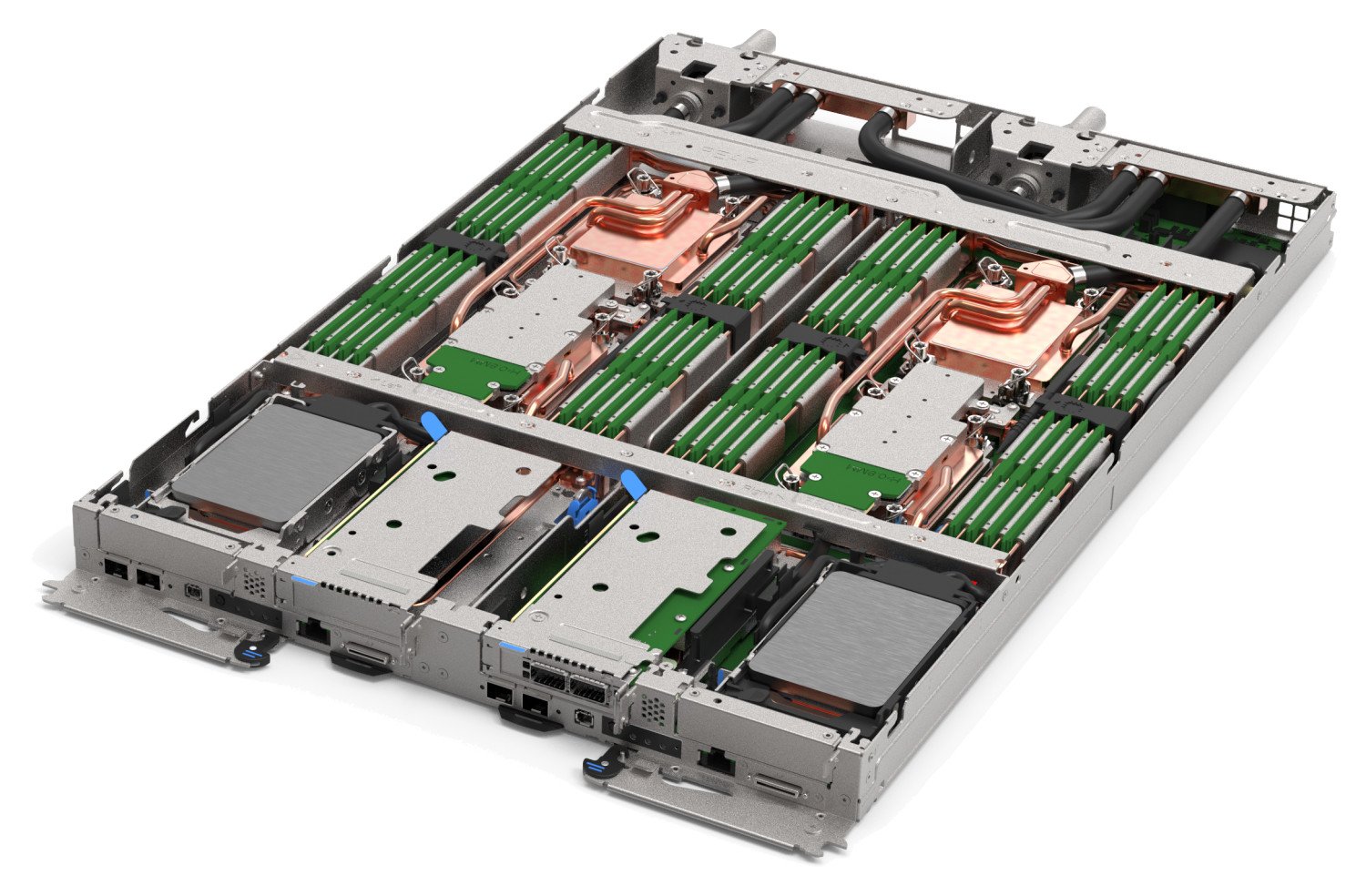
Figure 1. The Lenovo ThinkSystem SD650 V3 server tray with two distinct two-socket nodes supports Intel Xeon CPU Max Series processors
There are five models of the Intel Xeon Max Series that support 64 GB of HBM, up to 56 cores, and TDP values up to 350W, as listed in the following table.
As shown in the following figure, the Intel Xeon Max Series CPU contains four 16GB HBM die, one connected to each memory controller, for a total of 64 GB HBM in a processor. The figure also shows the 4th Gen Intel Xeon Scalable Processor (formerly codenamed "Sapphire Rapids").
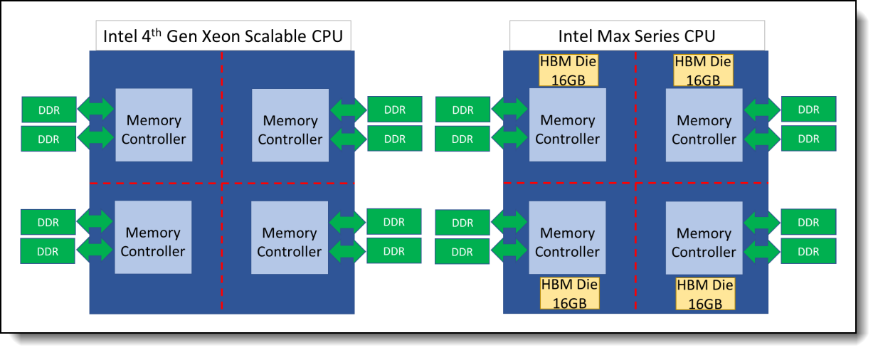
Figure 2. Architecture comparison between 4th Gen Intel Xeon Scalable CPU (left) and Intel Xeon Max Series CPU (right)
Memory modes
Intel HBM can configure into three different Memory Modes: HBM-Only Mode, Flat Mode, and Cache Mode. This section detail describes the pros and cons as well as the application scenario for each HBM Memory Mode.
SD650-I V3 support: The ThinkSystem SD650-I V3 only supports Cache Mode. HBM-Only Mode and Flat Mode are not supported.
HBM-Only Mode
In HBM-Only Mode, no regular DDR5 memory is installed; all memory functions are provided by the 64GB of HBM memory embedded in each processor. The supported OS and application recognize 64GB HBM memory per socket as the main memory.
The major advantage of this mode is HBM can achieve the highest memory bandwidth when a memory footprint is within the HBM memory capacity without any source code or software environment change needed. The drawback of HBM-Only Mode is the memory capacity would limit to 64GB per socket.
The following figure shows the HBM-Only Mode architecture under a single socket system.
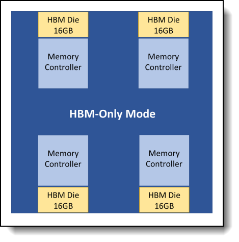
Figure 3. HBM-Only Mode on a single socket system
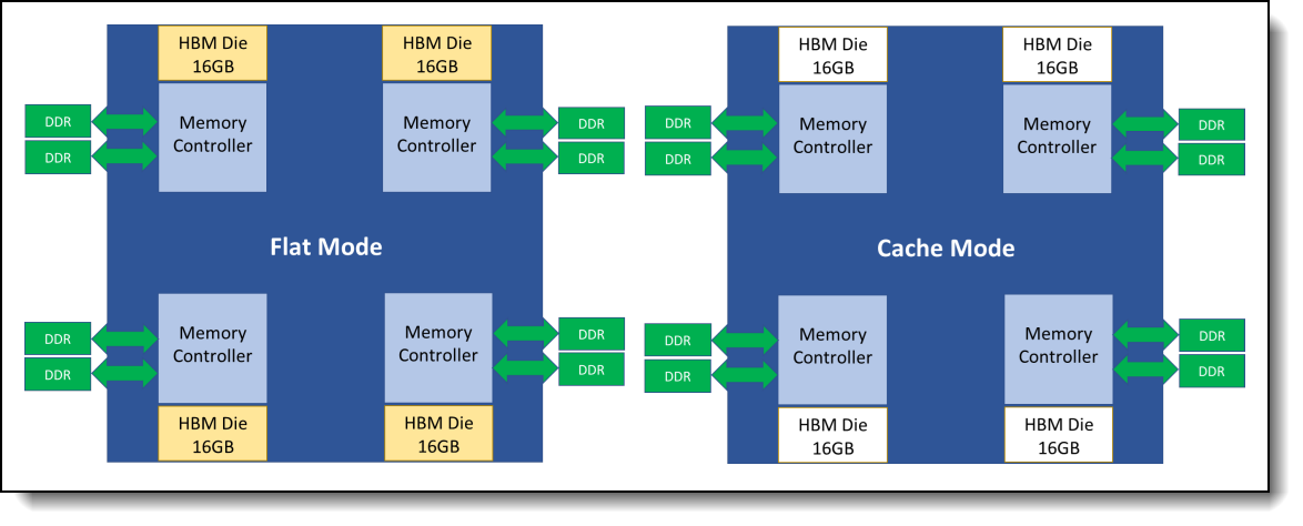
Flat Mode
To support applications with larger memory footprints, both HBM and DDR memory are configured as main memory in different NUMA address spaces under Flat Mode (also known as 1-Level Memory, 1LM). Besides the UEFI settings, additional software configuration steps are needed (Setup Flat Mode for HBM) to properly set up the NUMA address for HBM.
The following figure illustrates the hardware architecture of Flat Mode. In order to reach the highest performance under Flat Mode, binding applications into the proper NUMA domain with NUMA-aware tools (Setup Flat Mode for HBM) is essential.
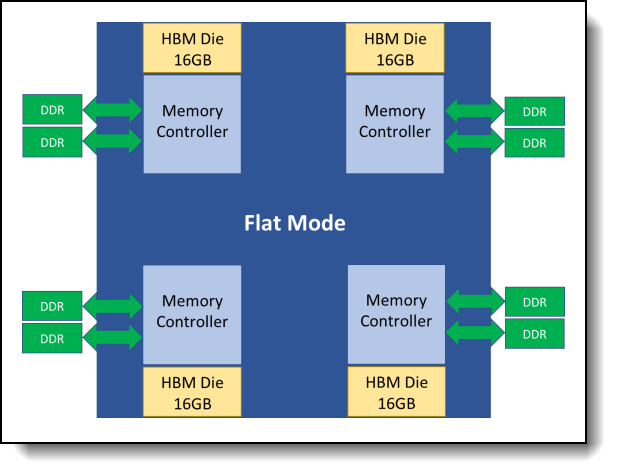
Figure 4. Flat Mode architecture on a single socket system
Cache Mode
Cache Mode (also known as 2-Level Memory mode, 2LM) addresses the small memory footprint issue of HBM-Only Mode as Flat Mode does. In contrast to Flat Mode, the HBM is invisible for both OS and application as shown in the following figure since the HBM is act as a level 4 cache for DDR ram not main memory under Cache Mode. As a result, there is no need to apply extra software configuration and performance tuning to address NUMA architecture. The drawback is the slightly lower performance compared to flat mode.
Clustering modes
To fulfill different user scenarios, each HBM memory mode can choose a clustering mode, Quadrant Mode or SNC4 Mode, to further partition HBM and/or DDR ram into different NUMA nodes. Combining three memory modes and two clustering modes Intel offered six configurations for Intel HBM as the table below shows.
Each clustering mode is described below.
Quadrant Mode
In Quadrant (Quad) mode, the whole 64 GB HBM form one single NUMA node in a CPU chip. It’s suited for large memory footprint and non-NUMA-optimized applications. The following figures depict the Quad mode of a dual-socket system under three different memory modes respectively.
HBM-Only Mode in Quad Clustering
There are two NUMA nodes when a dual-socket system is configured as HBM-Only Mode along with Quadrant Clustering.
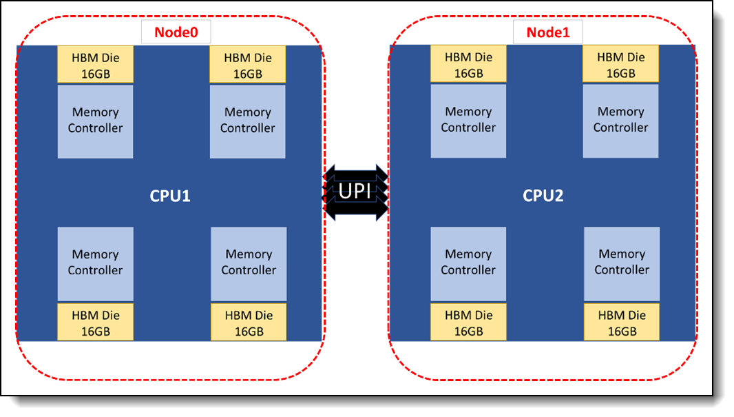
Figure 6. HBM-Only Mode along with Quad Clustering
Flat Mode in Quad Clustering
Four NUMA nodes is existing in a dual-socket system when Flat Mode along with Quadrant Clustering is configured, two for DDR RAM(Node 0 and 1) and two for HBM of each socket (Node 2 and 3).
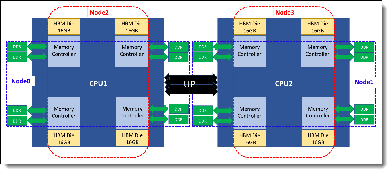
Figure 7. Flat Mode along with Quadrant Clustering
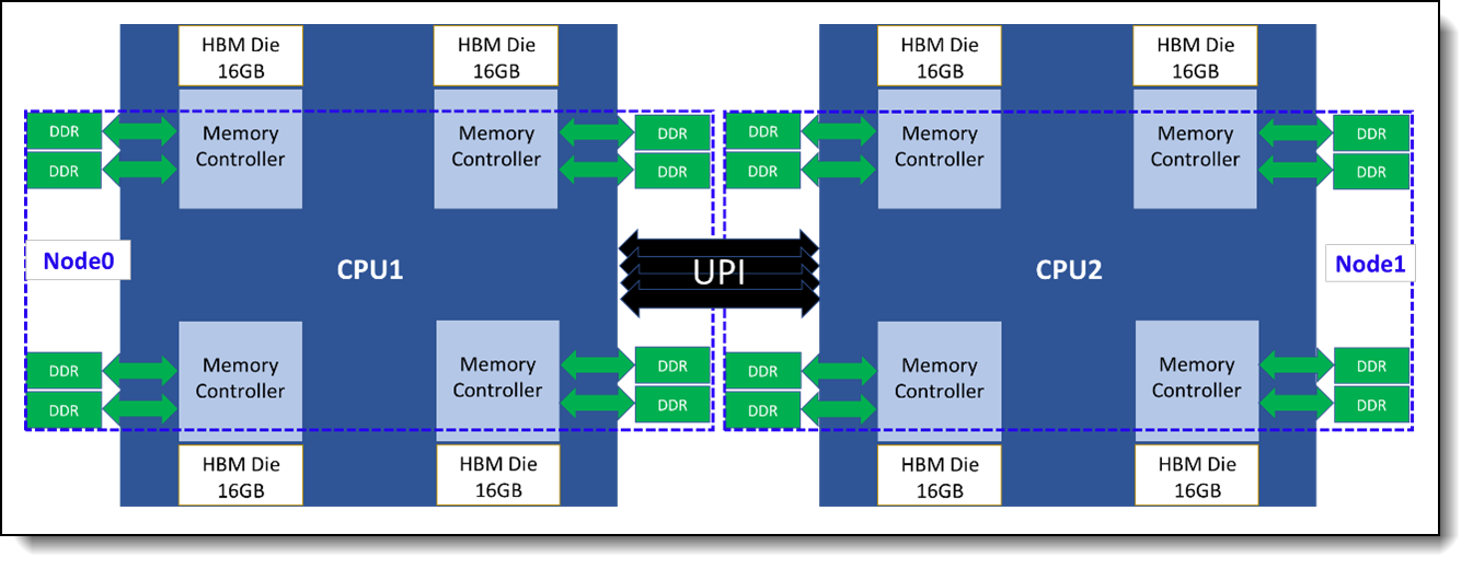
Cache Mode in Quad Clustering
Since HBM is invisible for OS under Cache Mode, there are only two NUMA nodes for DDR RAM of each CPU when a dual-socket system is under Quadrant Clustering.
SNC4 Mode
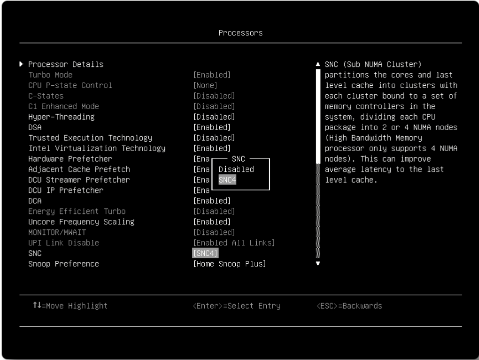
To further achieve higher memory bandwidth and lower memory latency for NUMA-optimized applications, the SNC4 Clustering divides 64 GB HBM memory into four independent NUMA nodes. This section describes SNC4 clustering using the three different memory modes.
HBM-Only Mode in SNC4 Clustering
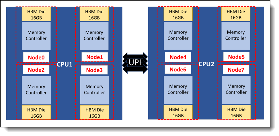
Figure 9. HBM-Only Mode in SNC4 Clustering
Each 16 GB HBM die in a CPU chip forms a NUMA node, a total of eight NUMA nodes for a two-socket system under HBM-Only Mode with SNC4 Clustering. Figure 9 shows the CPU cores assignment and memory capacity of each NUMA node under HBM-Only Mode with SNC4 Clustering by using the “numactl -H” command.
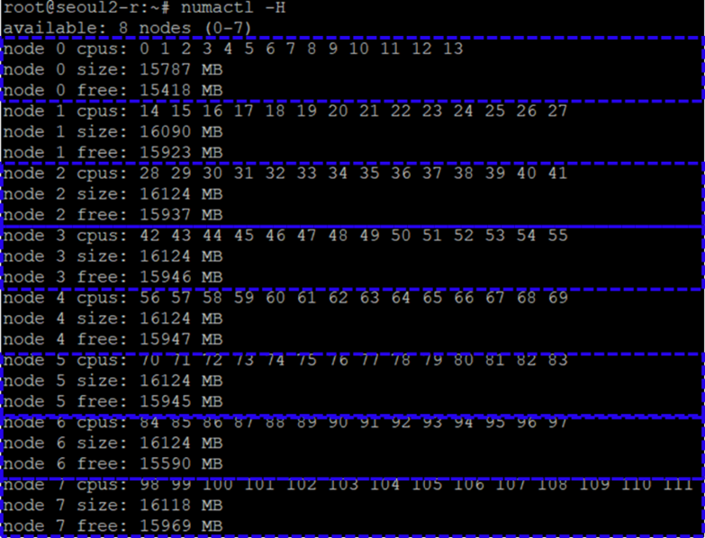
Figure 10. NUMA architecture of HBM-Only Mode under SNC4 Clustering
Flat Mode in SNC4 Clustering
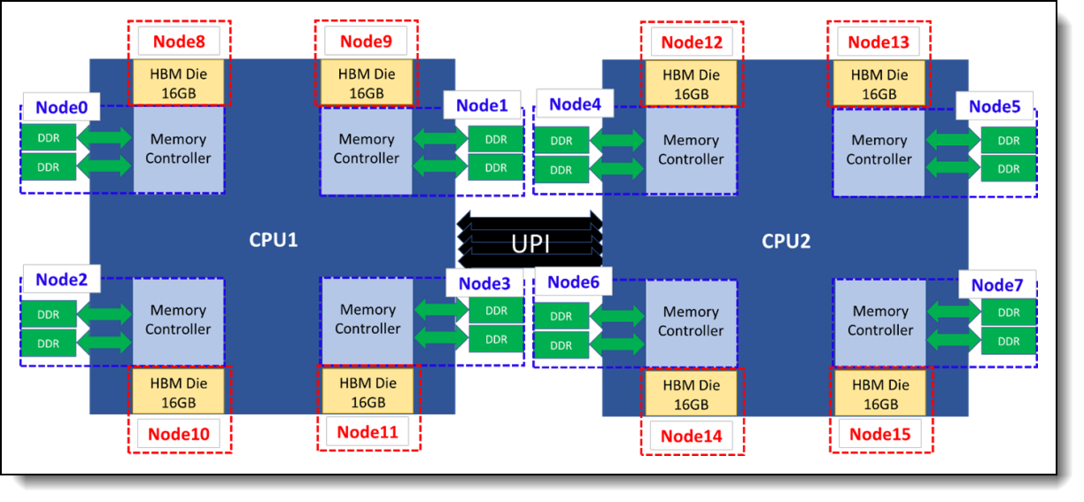
Figure 11. Flat Mode in SNC4 Clustering
Both HBM and DDR RAM would be partitioned into four independent NUMA under each HBM-based CPU, which means sixteen NUMA nodes exist in a two-socket system. Properly arranging applications into the NUMA nodes by using NUMA tools would help system performance significantly.
In the following figure, the blue dotted line NUMA nodes belongs to DDR memory with CPU cores close to it, and the red dotted line NUMA nodes belong to HBM.
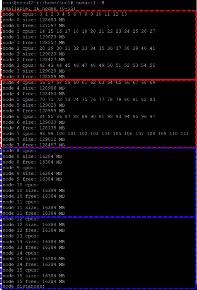
Figure 12. NUMA architecture of Flat Mode under SNC4 Clustering
Cache Mode in SNC4 Clustering
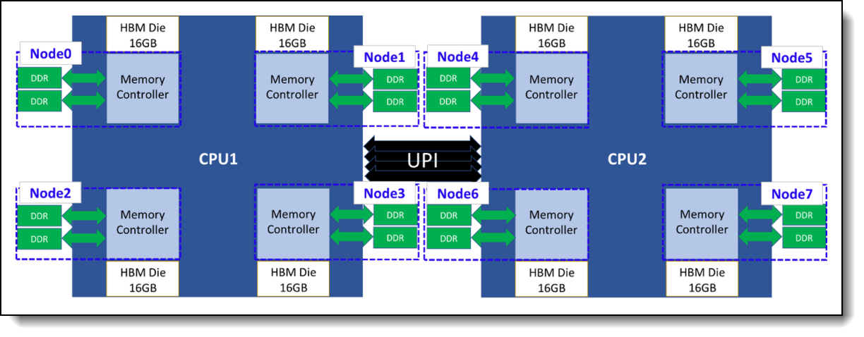
Figure 13. Cache Mode in SNC4 Clustering
Since HBM is invisible for OS under Cache Mode, there are only four NUMA nodes for DDR RAM of each CPU when a dual-socket system is under SNC4 Clustering. The following figure shows NUMA architecture of Cache Mode under SNC4 Clustering.
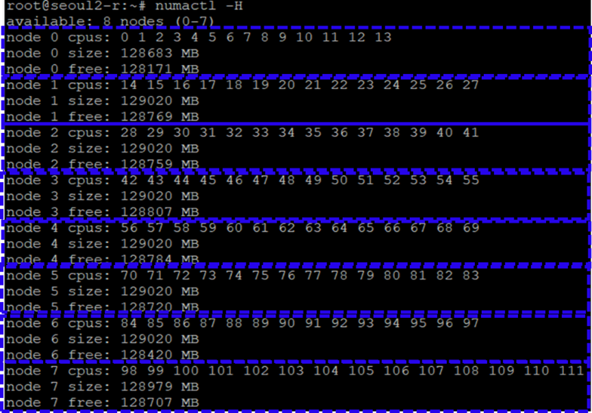
Figure 14. NUMA architecture of Cache Mode under SNC4 Clustering
Configuring HBM
This section instructs users how to set up UEFI and the operating system to operate in three different memory modes and two clustering modes of HBM.
Configuring Flat Mode
There are two steps to enable HBM in Flat Mode.
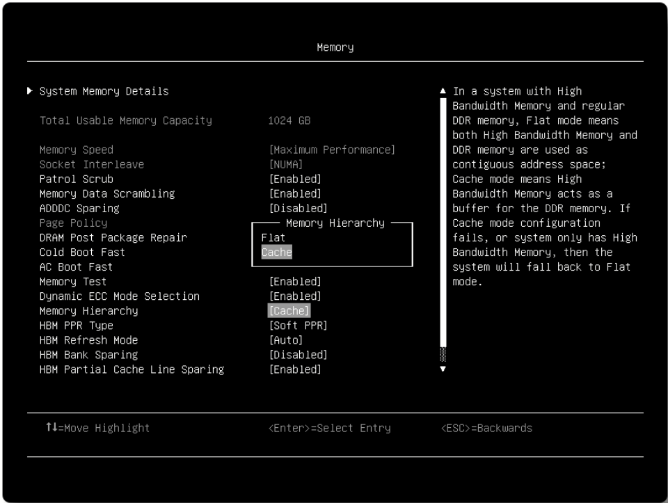
First of all, select “Flat” of “Memory Hierarchy” in System Setup (F1 at boot) by navigating to System Settings > Memory > Memory Hierarchy > Flat as shown in the following figure.
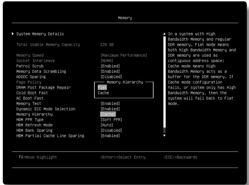
Figure 15. Setup HBM to Flat Mode
Secondly, use daxctl tool to configure the HBM address space for different Clustering Mode under OS, so that OS can recognize the HBM memory under Flat Mode. The daxctl tool can be install by use dnf command showed below:
# dnf install daxctl ndctl
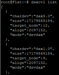
By using the “list” parameter, daxctl command dumps all the supported devices information including DAX name, size, mode … etc. in JSON format as shown in the following figure.
daxctl list
The “reconfigure-device” and “-m system-ram” parameters are then used to configure HBM into system memory according to the device name information obtained from “daxctl list”.
For Quadrant Mode of a dual socket system, follow the daxctl command below:
# daxctl reconfigure-device -m system-ram dax0.0
# daxctl reconfigure-device -m system-ram dax1.0
As shown in numactl output in the following figure, HBM devices named dax0.0 and dax1.0 are configured as system memory and assigned to two new NUMA domains, NUMA 2 and NUMA3 after applying daxctl command.
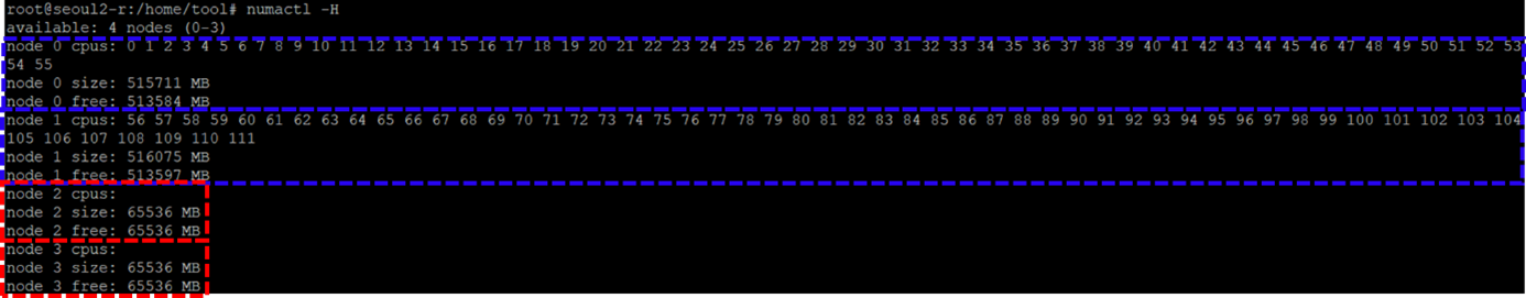
Figure 17. NUMA nodes under Flat mode with Quad Clustering
For SNC4 Mode of a dual socket system, follow the daxctl command below:
# daxctl reconfigure-device -m system-ram dax0.0
# daxctl reconfigure-device -m system-ram dax1.0
# daxctl reconfigure-device -m system-ram dax2.0
# daxctl reconfigure-device -m system-ram dax3.0
# daxctl reconfigure-device -m system-ram dax4.0
# daxctl reconfigure-device -m system-ram dax5.0
# daxctl reconfigure-device -m system-ram dax6.0
# daxctl reconfigure-device -m system-ram dax7.0
As Figure 12 shows, HBM devices named dax0.0 to dax7.0 are configured as system memory and assigned to eight new NUMA domains, NUMA 8 to 15 after applying daxctl command.
Since the HBM reconfigured process needs to apply on each time the system boot, it’s recommended that the system administrator implement it into OS boot process. Such automation can be achieved by writing script and execute by rc.local under the Linux based OS.
After “reconfigure-device”, the mode of will change from “devdax” to “system-ram” as shown in the following figure.
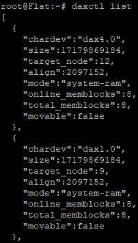
Figure 18. HBM information after reconfiguring to system memory
Measuring the performance of HBM
In this section, we use the Stream benchmark to compare the performance of HBM memory in the Intel Xeon Max Series processors and to that of DDR5 memory and 4th Gen Intel Xeon Scalable processors.
The experiments were performed on the Lenovo ThinkSystem SD650 V3, which is a dual-socket server that features the two 4th Gen Intel Xeon Scalable processors or two Intel Max Series processors. With up to 60 cores per processor and supporting the fifth-generation Lenovo Neptune direct water-cooling technology, the SD650 V3 provides the best system performance in a 2U form factor.
For more information about SD650 V3, see the Lenovo Press product guide:
https://lenovopress.lenovo.com/lp1603-thinksystem-sd650-v3-server
The configuration used for the experiment consisted of the following:
- 1x Lenovo ThinkSystem SD650 V3 node
- Processors:
- For DDR5-only testing: 2x Intel Xeon Platinum 8490H Processors (60 cores, 1.90 GHz)
- For HBM testing: 2x Intel Xeon Max CPU 9480 Processors (56 cores, 1.90 GHz)
- DDR5 memory: 1 TB memory (12x 64GB RDIMMs) running at 4800 MHz
- 1x 480 GB SATA 2.5-inch SSD
- Ubtuntu 22.04 with kernel 5.19.0-051900rc6-generic
The stream benchmark was used to measure the memory bandwidth for both HBM and DDR5 memory on the ThinkSystem SD650 V3 server.
As shown in the following figure, the configuration with Intel Xeon Max Series processor delivers up to 2.28X memory bandwidth compared to the Intel Xeon Platinum processor configuration with only DDR5 memory.
The SNC4 Clustering with proper CPU and memory binding achieved more than 25% higher memory bandwidth compared to Quad Clustering no matter which HBM memory mode it is. In order to well utilize the memory bandwidth, we recommend configuring HBM with SNC4 clustering for NUMA-optimized applications whose memory footprint fits in each of the NUMA domains.
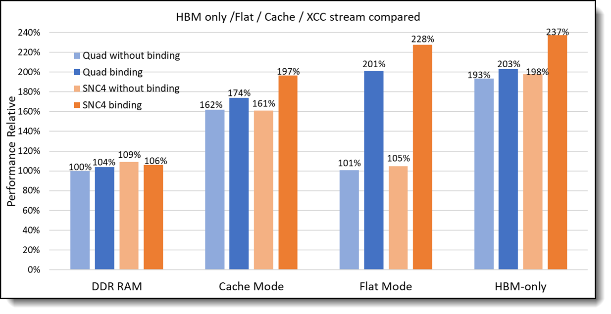
Figure 21. Memory bandwidth of HBM and DDR Memory
The Cache Mode has the lowest memory bandwidth compared to other HBM memory modes. The HBM is configured as system memory under both HBM-Only Mode and Flat Mode, hence NUMA tool needs to be applied to achieve the best memory bandwidth. Especially for Flat Mode, its CPU cores are not assigned to HBM NUMA nodes by daxctl tool (see bottom of Figure 12), the OS is not able to automatically assign the correct CPU cores to the user applications.
The following numactl commands are an example on how to bind the CPU cores for the STREAM benchmark under Ubuntu OS with Quadrant Clustering.
# numactl -C 0-55 -p 2 ./stream &
# numactl -C 56-111 -p 3 ./stream
Similarly, to reach the best memory bandwidth for a dual-socket system with Flat Mode in SNC4 Clustering, the -C and -P parameters need to be applied for each NUMA node, using the commands shown below.
# numactl -C 0-13 -p 8  ./stream &
# numactl -C 14-27 -p 9  ./stream &
# numactl -C 27-41 -p 10  ./stream &
# numactl -C 42-55 -p 11  ./stream &
# numactl -C 56-69 -p 12  ./stream &
# numactl -C 70-83 -p 13  ./stream &
# numactl -C 84-97 -p 14  ./stream &
# numactl -C 98-111 -p 15  ./stream
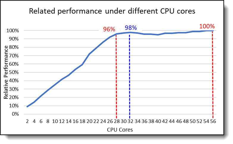
Besides the NUMA binding, minimal CPU cores are required to liberate the HBM bandwidth. The HBM memory bandwidth measurement through the STREAM benchmark with CPU cores used from 2 to 56 under Flat Mode with Quad Clustering as shown in the following figure.
All CPU cores are needed for STREAM to reach the highest memory bandwidth(100%), noting that 96% of HBM memory bandwidth can be reached with only half of the CPU cores (28 cores), and four more CPU cores are needed to obtain an extra 2% memory bandwidth(98%). Because of OpenMP communication overhead, memory bandwidth is drift after 32 CPU cores until all 56 cores are used to reach 100%. Based on the chart below, users are able to find the balance between the CPU cores used and the memory bandwidth needed for their applications.
Recommendations
For the selection of memory mode and clustering mode, we recommend the following:
- If your workload's memory footprint is less than 64 GB (or 128 GB if 2 processors are installed), use HBM-only Mode to maximize memory bandwidth
- If your workload's memory footprint is larger than 64 GB (or 128 GB if 2 processors are installed), Flat Mode has better memory bandwidth compared to Cache Mode when the proper binding is applied, however Flat Mode will result in worse performance without proper binding. If you are unsure about binding, select Cache Mode.
- If your workload is NUMA optimized, we recommend you use SNC4 clustering to improve memory bandwidth
- If your workload is not NUMA optimized, use Quadrant Clustering to avoid higher latency across NUMA nodes
More information
For more information, consult these resources:
- STREAM Benchmark Reference Information
http://www.cs.virginia.edu/stream/ref.html - ThinkSystem SD650 V3 web page
https://www.lenovo.com/us/en/p/high-density/len21ts0014 - Thinksystem SD650 V3 product guide
https://lenovopress.lenovo.com/lp1603-thinksystem-sd650-v3-server - Intel Xeon CPU Max Series product page
https://www.intel.com/content/www/us/en/products/details/processors/xeon/max-series.html
Authors
Sam Kuo is a performance engineer in the Lenovo Infrastructure Solutions Group Laboratory in Taipei Taiwan. Sam joined Lenovo in June 2021. Prior to this, he worked at Wistron as Electronic Engineer, designing system motherboards for both PC and notebooks, verifying motherboard function, debugging and analyzing critical system issues, furthermore he also participated in system performance validation by running industrial standard performance benchmarks. Sam holds a Master’s Degree in Electronical Engineering, Division of communication and Electromagnetic Waves from Tamkang University in Taiwan, and a Bachelor’s Degree in Electronical Engineering from Tamkang University in Taiwan.
Jimmy Cheng is a performance engineer in the Lenovo Infrastructure Solutions Group Laboratory in Taipei Taiwan. Jimmy joined Lenovo in December 2016. Prior to this, he worked on IBM POWER system assurance and validation, ATCA system integration, automation development as well as network performance. Jimmy holds a Master’s Degree in Electronic and Computer Engineering from National Taiwan University of Science and Technology in Taiwan, and a Bachelor’s Degree in Computer Science and Engineering from Yuan-Ze University, Taiwan.
Trademarks
Lenovo and the Lenovo logo are trademarks or registered trademarks of Lenovo in the United States, other countries, or both. A current list of Lenovo trademarks is available on the Web at https://www.lenovo.com/us/en/legal/copytrade/.
The following terms are trademarks of Lenovo in the United States, other countries, or both:
Lenovo®
Neptune®
ThinkSystem®
The following terms are trademarks of other companies:
Intel®, the Intel logo and Xeon® are trademarks of Intel Corporation or its subsidiaries.
Linux® is the trademark of Linus Torvalds in the U.S. and other countries.
DAX is a trademark of Microsoft Corporation in the United States, other countries, or both.
Other company, product, or service names may be trademarks or service marks of others.
Configure and Buy
Please select a locale
Full Change History
Course Detail
Employees Only Content
The content in this document with a is only visible to employees who are logged in. Logon using your Lenovo ITcode and password via Lenovo single-signon (SSO).
The author of the document has determined that this content is classified as Lenovo Internal and should not be normally be made available to people who are not employees or contractors. This includes partners, customers, and competitors. The reasons may vary and you should reach out to the authors of the document for clarification, if needed. Be cautious about sharing this content with others as it may contain sensitive information.
Any visitor to the Lenovo Press web site who is not logged on will not be able to see this employee-only content. This content is excluded from search engine indexes and will not appear in any search results.
For all users, including logged-in employees, this employee-only content does not appear in the PDF version of this document.
This functionality is cookie based. The web site will normally remember your login state between browser sessions, however, if you clear cookies at the end of a session or work in an Incognito/Private browser window, then you will need to log in each time.
If you have any questions about this feature of the Lenovo Press web, please email David Watts at dwatts@lenovo.com.


