Author
Updated
21 Aug 2025Form Number
LP1884PDF size
20 pages, 2.2 MBAbstract
The Lenovo zero-U (0U) Basic and Switched and Monitored power distribution units (PDUs) are the ideal solutions when you need flexible, reliable, easy-to-deploy power distribution with branch circuit protection to minimize downtime. The 0U PDUs are designed to be installed vertically in a Lenovo rack, thereby not consuming any horizontal rack space.
This product guide provides essential presales information to understand the 0U Basic and Switched and Monitored PDUs and their key features, specifications, and compatibility. This guide is intended for technical specialists, sales specialists, sales engineers, IT architects, and other IT professionals who want to learn more about the Basic and Switched and Monitored PDUs and consider their use in IT solutions.
Change History
Changes in the August 21, 2025 update:
- Added the following under Related publications and links section
- nVent Lenovo product page
Introduction
The Lenovo zero-U (0U) Basic and Switched and Monitored power distribution units (PDUs) are the ideal solutions when you need flexible, reliable, easy-to-deploy power distribution with branch circuit protection to minimize downtime. These rack-dense units distribute power to up to 48 outlets and 42 outlets. 0U PDUs are designed to be installed vertically in the rear channel of a Lenovo rack, thereby not consuming any horizontal rack space that otherwise be used by servers, storage and network switches (hence the term 0U).
The following figure displays the Lenovo zero-U (0U) PDUs. (v1 and v2 models are identical).
Did you know?
With ever growing power densities in today’s rack environments, it is all too easy to add load in the wrong place and trigger an overload event. The 0U Basic and Switched and Monitored PDU offerings can minimize this impact, providing the ability to quickly recover with resettable circuit breakers for each designated bank of receptacles, referred to as load groups. Breakers are color coded to the receptacles in a particular load group to aid in configuration, installation, and maintenance. Furthermore, the Basic PDUs offer a cost-effective option to users who do not require intelligence. The Switched and Monitored PDUs also offer individual outlet remote monitoring and switching (on/off), which allow for remote power sequencing and further helping to prevent unintended PDU overloading.
Introduction to PDUs
A power distribution unit (PDU) is a highly reliable, multiple outlet power strip designed to consolidate line cords within the rack and distribute conditioned power from an uninterruptible power supply (UPS) or utility power to servers and other IT equipment. The PDU efficiently distributes power within the rack and provides fault-tolerant power redundancy for high availability requirements.
There are two types of 0U PDUs available from Lenovo. The PDUs covered in this document are:
- Basic PDUs: The simplest and most cost-effective power distribution. Available with various outlet configurations and line cord options to support different systems and load requirements.
- Switched & monitored PDUs: These are advanced power management solutions, providing power monitoring at the outlet level, with increased accuracy at low amperages, for more precise views of power consumption down to the individual server level instead of at the consolidated load group. These PDUs also offer management via a web-based interface which includes individual outlet switching (on/off). Outlet switching allows for remote power sequencing and helps prevent unintended PDU overloading.
Basic PDUs
The Basic PDUs offer a cost-effective option to users who do not require intelligence. Premium hydraulic-magnetic circuit breakers operate reliably in high temperature environments.
The following tables provide the ordering part numbers for the Basic PDUs.
| Part number |
Feature code |
Description |
ANZ
|
ASEAN
|
Brazil
|
EET
|
MEA
|
RUCIS
|
WE
|
HTK
|
INDIA
|
JAPAN
|
LA
|
NA
|
PRC
|
|---|---|---|---|---|---|---|---|---|---|---|---|---|---|---|---|
| 4PU7A93169 | C0DA | 0U 36 C13 and 6 C19 Basic 32A 1 Phase PDU | Y | Y | Y | Y | Y | Y | Y | Y | Y | N | Y | Y | Y |
| 4PU7A93170 | CBVF | 0U 24 C13/C15 and 24 C13/C15/C19 Basic 32A 3 Phase WYE PDU | Y | Y | Y | Y | Y | Y | Y | Y | Y | Y | Y | Y | Y |
| 4XF7A93901 | C0XG | 0U PDU Mounting Bracket for 9307 Rack | Y | Y | Y | Y | Y | Y | Y | Y | Y | Y | Y | Y | Y |
| Part number |
Feature code |
Description |
ANZ
|
ASEAN
|
Brazil
|
EET
|
MEA
|
RUCIS
|
WE
|
HTK
|
INDIA
|
JAPAN
|
LA
|
NA
|
PRC
|
|---|---|---|---|---|---|---|---|---|---|---|---|---|---|---|---|
| 4PU7A93176 | C0QH | 0U 36 C13 and 6 C19 Basic 32A 1 Phase PDU v2 | Y | Y | Y | Y | Y | Y | Y | Y | Y | N | Y | Y | Y |
| 4PU7A93177 | C0QJ | 0U 24 C13/C15 and 24 C13/C15/C19 Basic 32A 3 Phase WYE PDU v2 | Y | Y | Y | Y | Y | Y | Y | Y | Y | Y | Y | Y | Y |
The following table shows the orderable part number, feature code and CTO (Machine Type/Model) for the v2 Basic PDU models.
Table 3. Ordering part number, feature code and CTO models
| Description | Part number | Feature code | CTO |
| V2 Basic PDUs | |||
| 0U 36 C13 and 6 C19 Basic 32A 1 Phase PDU v2 | 4PU7A93176 | C0QH | 7DGLCTO1WW |
| 0U 24 C13/C15 and 24 C13/C15/C19 Basic 32A 3 Phase WYE PDU v2 | 4PU7A93177 | C0QJ | 7DGLCTO1WW |
Included with the PDUs
The PDUs include the following items:
- One Power Distribution Unit with an attached power cord
- Mounting hardware
- PDU warranty poster
- Safety guidelines
- Quick start guide
The following figure displays the Basic PDUs. (v1 and v2 models are identical).

Figure 2. Lenovo 0U Basic PDUs
| Supported markets | Unsupported markets |
|---|---|
|
|
| Supported markets | Unsupported markets |
|---|---|
|
(None) |
| Supported markets | Unsupported markets |
|---|---|
|
(None) |
| Supported markets | Unsupported markets |
|---|---|
|
(None) |
| Supported markets | Unsupported markets |
|---|---|
|
(None) |
| Supported markets | Unsupported markets |
|---|---|
|
(None) |
| Supported markets | Unsupported markets |
|---|---|
|
|
| Supported markets | Unsupported markets |
|---|---|
|
(None) |
| Supported markets | Unsupported markets |
|---|---|
|
(None) |
| Supported markets | Unsupported markets |
|---|---|
|
(None) |
Features and specifications basic PDUs
The 0U Basic PDUs have the following common features:
- Advanced features, such as color-coded standard IEC outlets
- Enlogic's standard low-profile design
- Toolless mounting
- Operate reliably in high temperature environments.
Note: Network Management Module is not supported
The following tables compare the technical and environmental specifications of the 0U Basic PDUs.
Note: The Basic v1 and v2 are functionally identical
Switched and Monitored PDUs
The following tables provide the ordering part numbers for the 0U Switched and Monitored PDUs.
| Part number |
Feature code |
Description |
ANZ
|
ASEAN
|
Brazil
|
EET
|
MEA
|
RUCIS
|
WE
|
HTK
|
INDIA
|
JAPAN
|
LA
|
NA
|
PRC
|
|---|---|---|---|---|---|---|---|---|---|---|---|---|---|---|---|
| 4PU7A93174 | CBVJ | 0U 21 C13/C15 and 21 C13/C15/C19 Switched and Monitored 60A 3 Phase Delta PDU | Y | Y | Y | Y | Y | Y | Y | Y | Y | Y | Y | Y | Y |
| 4PU7A93171 | C0D8 | 0U 20 C13 and 4 C19 Switched and Monitored 32A 1 Phase PDU | Y | Y | Y | Y | Y | Y | Y | Y | Y | N | Y | Y | Y |
| 4PU7A93175 | C0CS | 0U 18 C13/C15 and 18 C13/C15/C19 Switched and Monitored 63A 3 Phase WYE PDU | Y | Y | Y | Y | Y | Y | Y | Y | Y | N | Y | Y | Y |
| 4PU7A93173 | CBVH | 0U 18 C13/C15 and 18 C13/C15/C19 Switched and Monitored 32A 3 Phase WYE PDU | Y | Y | Y | Y | Y | Y | Y | Y | Y | Y | Y | Y | Y |
| 4PU7A93172 | CBVG | 0U 16 C13/C15 and 16 C13/C15/C19 Switched and Monitored 30A 1 Phase PDU | Y | Y | Y | Y | Y | Y | Y | Y | Y | Y | Y | Y | Y |
| 4XF7A93184 | C0D2 | PDU Environmental Sensor- Temperature & Humidity | Y | Y | Y | Y | Y | Y | Y | Y | Y | Y | Y | Y | Y |
| 4X97A93183 | C0D3 | PDU serial communication Cable | Y | Y | Y | Y | Y | Y | Y | Y | Y | Y | Y | Y | Y |
| 4XF7A93901 | C0XG | 0U PDU Mounting Bracket for 9307 Rack | Y | Y | Y | Y | Y | Y | Y | Y | Y | Y | Y | Y | Y |
| Part number |
Feature code |
Description |
ANZ
|
ASEAN
|
Brazil
|
EET
|
MEA
|
RUCIS
|
WE
|
HTK
|
INDIA
|
JAPAN
|
LA
|
NA
|
PRC
|
|---|---|---|---|---|---|---|---|---|---|---|---|---|---|---|---|
| 4PU7A93181 | C0QN | 0U 21 C13/C15 and 21 C13/C15/C19 Switched and Monitored 48A 3 Phase Delta PDU v2 (60A derated) | N | Y | N | N | N | N | N | Y | N | Y | N | Y | N |
| 4PU7A93178 | C0QK | 0U 20 C13 and 4 C19 Switched and Monitored 32A 1 Phase PDU v2 | Y | Y | Y | Y | Y | Y | Y | Y | Y | N | Y | Y | Y |
| 4PU7A93182 | C0QP | 0U 18 C13/C15 and 18 C13/C15/C19 Switched and Monitored 63A 3 Phase WYE PDU v2 | Y | Y | Y | Y | Y | Y | Y | Y | Y | Y | Y | Y | Y |
| 4PU7A93180 | C0QM | 0U 18 C13/C15 and 18 C13/C15/C19 Switched and Monitored 32A 3 Phase WYE PDU v2 | Y | Y | Y | Y | Y | Y | Y | Y | Y | Y | Y | Y | Y |
| 4PU7A93179 | C0QL | 0U 16 C13/C15 and 16 C13/C15/C19 Switched and Monitored 24A 1 Phase PDU v2 (30A derated) | N | Y | N | N | N | N | N | Y | N | Y | N | Y | N |
The following table shows the orderable part number, feature code and CTO (Machine Type/Model) for the Switched and Monitored v2 PDU models.
Table 9. Ordering part number, feature code and CTO models
| Description | Part number | Feature code | CTO |
| Switched and Monitored v2 PDUs | |||
| 0U 21 C13/C15 and 21 C13/C15/C19 Switched and Monitored 48A 3 Phase Delta PDU v2 (60A derated) | 4PU7A93181 | C0QN | 7DGMCTO1WW |
| 0U 20 C13 and 4 C19 Switched and Monitored 32A 1 Phase PDU v2 | 4PU7A93178 | C0QK | 7DGMCTO1WW |
| 0U 18 C13/C15 and 18 C13/C15/C19 Switched and Monitored 63A 3 Phase WYE PDU v2 | 4PU7A93182 | C0QP | 7DGMCTO1WW |
| 0U 18 C13/C15 and 18 C13/C15/C19 Switched and Monitored 32A 3 Phase WYE PDU v2 | 4PU7A93180 | C0QM | 7DGMCTO1WW |
| 0U 16 C13/C15 and 16 C13/C15/C19 Switched and Monitored 24A 1 Phase PDU v2 (30A derated) | 4PU7A93179 | C0QL | 7DGMCTO1WW |
Included with the PDUs
The PDU unit is delivered in a corrugated box and contains:
- One Power Distribution Unit with an attached power cord
- Network Management Controller (NMC is pre-installed)
- Plugs and wires
- Safety information sheet
- Quick start guide
- Warranty card
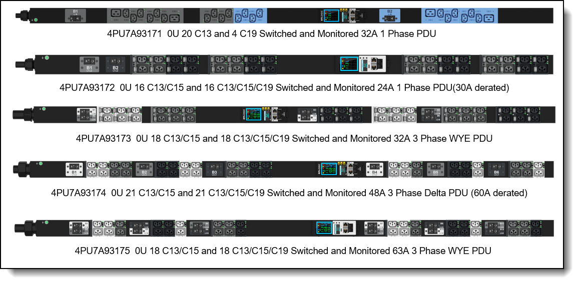
The following figure displays the 0U Switched and Monitored PDUs. (v1 and v2 models are identical)
Figure 3. Lenovo 0U Switched and Monitored PDUs
| Supported markets | Unsupported markets |
|---|---|
|
(None) |
| Supported markets | Unsupported markets |
|---|---|
|
(None) |
| Supported markets | Unsupported markets |
|---|---|
|
|
| Supported markets | Unsupported markets |
|---|---|
|
(None) |
| Supported markets | Unsupported markets |
|---|---|
|
|
| Supported markets | Unsupported markets |
|---|---|
|
(None) |
| Supported markets | Unsupported markets |
|---|---|
|
(None) |
| Supported markets | Unsupported markets |
|---|---|
|
(None) |
| Supported markets | Unsupported markets |
|---|---|
|
(None) |
| Supported markets | Unsupported markets |
|---|---|
|
(None) |
| Supported markets | Unsupported markets |
|---|---|
|
(None) |
| Supported markets | Unsupported markets |
|---|---|
|
(None) |
| Supported markets | Unsupported markets |
|---|---|
|
(None) |
| Supported markets | Unsupported markets |
|---|---|
|
(None) |
| Supported markets | Unsupported markets |
|---|---|
|
(None) |
| Supported markets | Unsupported markets |
|---|---|
|
(None) |
| Supported markets | Unsupported markets |
|---|---|
| (None) |
|
| Supported markets | Unsupported markets |
|---|---|
| (None) |
|
| Supported markets | Unsupported markets |
|---|---|
|
(None) |
| Supported markets | Unsupported markets |
|---|---|
|
(None) |
| Supported markets | Unsupported markets |
|---|---|
|
(None) |
| Supported markets | Unsupported markets |
|---|---|
|
(None) |
| Supported markets | Unsupported markets |
|---|---|
|
(None) |
| Supported markets | Unsupported markets |
|---|---|
|
(None) |
| Supported markets | Unsupported markets |
|---|---|
| (None) |
|
| Supported markets | Unsupported markets |
|---|---|
| (None) |
|
Features and specifications switched and monitored PDUs
The 0U Switched & Monitored PDUs have the following common and intelligent features like:
- Advanced features, such as color-coded with locking IEC outlets
- Enlogic's standard low-profile design
- Toolless mounting
- Operate reliably in high temperature environments.
- Sleek and space saving unit with low profile circuit breakers
- Color-coded receptacles and different type of power outlets which can be customized according to needs and IT requirements.
- Support Network Management Module and alerting capabilities supporting HTTP, HTTPS, SSH, SNMP, and email.
- Support encryption, passwords, and advanced authorization options including local permissions, LDAP/S, and Active Directory.
- Daisy Chain up to 64 Rack PDUs and supports a maximum of 10 environmental sensors each (sensors are optional)
- Power Sharing feature that allows the data of the PDU to be recorded even during a Power Failure.
- The Switched & Monitored PDUs also provide both current options with unique features:
- Single-Phase Models:
- All Single-Phase model support hydraulic magnetic breakers that are colour coded to the corresponding outlets.
- Three-Phase Models:
- In standard 415 V Three-Phase (Wye) configurations, the colour of each circuit breaker and outlet correspond to the appropriate input phase. The PDU is labelled to indicate the input-phase associated with each circuit breaker and outlets.
- In North America 208 V Three-phase (delta) configurations, the colour of the circuit breaker corresponds to the line connections and includes a label of the two connected input-phases
- Single-Phase Models:
The following tables compare the technical and environmental specifications of the 0U Switched and Monitored PDUs.
Note: The Switched and Monitored v1 and v2 are functionally identical
* USA, Canada
** USA, Canada, and Japan
* USA, Canada
** USA, Canada, and Japan
Connectors and load groups
The 0U Basic PDU with 36x C13 and 6x C19 connectors (part number 4PU7A93169 or 4PU7A93176) have the components as shown in the following figure.

Figure 4. Connectors for Basic PDU (part number 4PU7A93169 or 4PU7A93176)
The 0U Switched and Monitored PDUs with 18x C13/C15 and 18x C13/C15/C19 connectors (part number 4PU7A93175 or 4PU7A93182) have the components and controls as shown in the following figure.

Figure 5. Connectors for Switched and Monitored PDU (part number 4PU7A93175 or 4PU7A93182)
Advanced Network Management
The Switched and Monitored PDUs include a hot-swappable Network Management Controller (NMC) that provides the interface and connectors to manage the PDU.
Features:
- Network Connectivity: Dual ports: 1x Gigabit Ethernet (10/100/1000 Mbps) and 1x (10/100 Mbps) connection/IP address
- Ethernet Cascading: Up to 64 units share a single “daisy-chain” Ethernet connection/IP address
- DC Power Sharing: Each PDU can provide DC power sufficient to power network management electronics and sensors in a neighboring PDU in the event of AC power source loss
- Dual Ethernet Support: Dual Ethernet ports for redundant communication
- Remote Connectivity: HTTP(s), iPV4 and iPV6, SSH, Virtual Serial, SNMP (v1, v2c, v3), JSON-RPC, LDAP(S), FTP/SFTP, RADIUS, Redfish DMTF RESTful API
- WebUI Interfacce: Data efficient REACT framework with native mobile device support
The following figure shows the LED screen and the ports of the NMC. The LED interface provides information about the load status, events, measurements, identification, and settings.
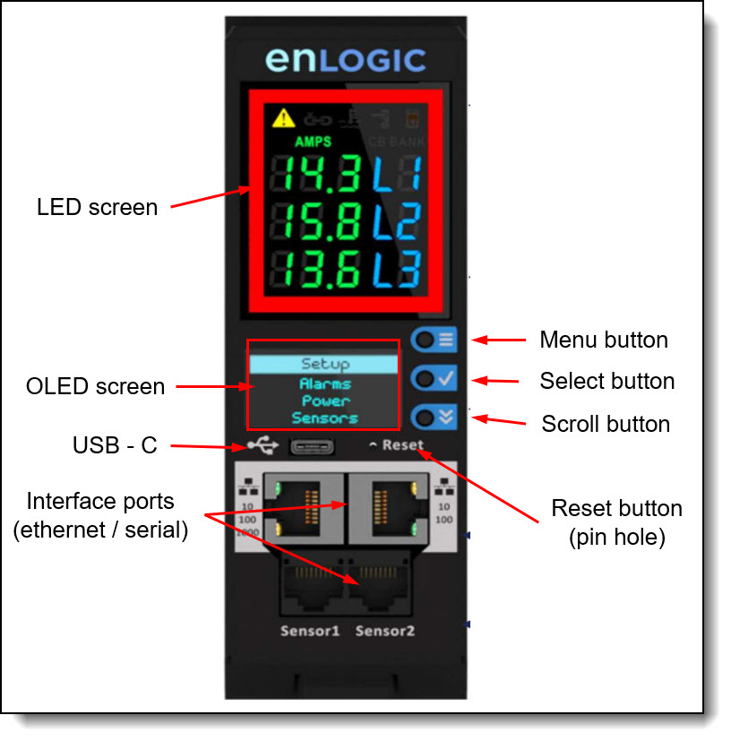
Figure 6. Interface of the Network Management Controller
The components of the NMC are as follows:
- LED screen:
- Graphical alarm icon PDU Alarm
- Daisy Chain Indicator
- Environmental Sensor Alarm
- Security Sensor Alarm
- Circuit Breaker & outlet Alarm
- Source color coding - user selected option
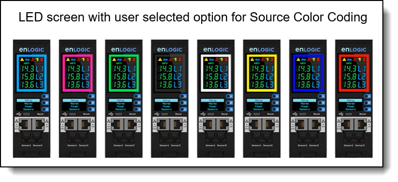
Figure 7. LED screen source color coding samples
- OLED Screen:
- Setup
- Alarms
- Power
- Sensors
- Reset button: Use this button to reset the PDU for communication purposes only. Resetting the PDU does not affect the outlets/loads.
- Interface Ports:
- USB-C port: Use the USB connection to upgrade firmware and configuration file download/upload.
- Ethernet ports: Use for redundancy and cascading (daisy chain)
- 1x Gigabit Ethernet (10/100/1000 Mbps)
- 1x (10/100 Mbps)
- Serial ports:
- Digital Sensor port 1: dual function - sensor or serial connectivity. Use this port to open a serial connection to the PDU from your laptop.
- Digital Sensor port 2: sensor connectivity
- Supports up to 10 physical sensors (optional sensors such as: door open/close, fluid spot leak detector, humidity, temperature available thru Enlogic vendor)
- Daisy chain port:
- 1x Gigabit Ethernet (10/100/1000 Mbps) port on PDU1 to 1x (10/100 Mbps) port on PDU2.
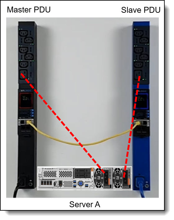
- Use ports to daisy chain two PDUs together. This setup enables multiple PDUs to connect over one Ethernet port. In daisy chain mode, up to 64 PDUs can be connected via one (1) IP address. This allows user to gather information and data of all daisy chained PDUs from the master PDU.
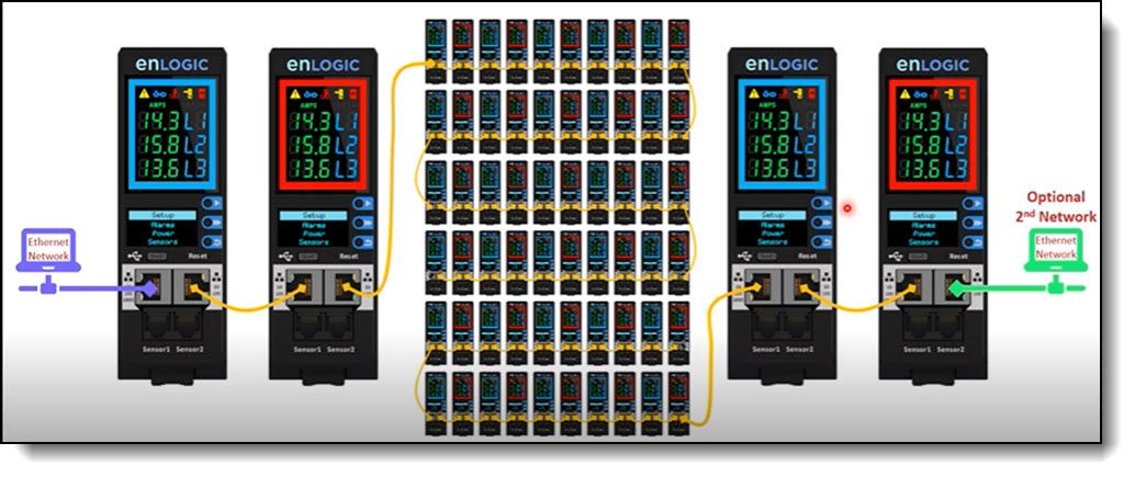
Figure 8. Daisy-chain PDU setup
RNA (Redundant Network Access) Functionality
- Enlogic RNA allows to secure the access of PDU data and statistics on two separate private networks.
- RNA is used with a redundant power delivery design including two rack PDUs for each IT rack. PDUs are used in RNA applications that must be of the same SKU.
The following is a sample of RNA connectivity
Browser interface
The PDU provides a graphical user interface that you can view from a web browser. Using a web browser, you can access and monitor the PDU power outlets and output devices remotely from a computer.
The following tasks can be performed though browser interface:
- Controls individual outlets (On/Off)
- Displays PDU current, watts, output power in VA, power factor, and frequency
- Displays outlet level voltage, power factor and cumulative KW hour output
- Sets outlet alarm thresholds
- Views temperature and humidity status where the PDU is located and set thresholds to trigger alarm notifications
- Views dry, humidity and temperature status
- Accesses a graphical historical view of PDU data for statistical trend analysis
- Views PDU Alarms
- Views Event/System Logs
Environment Probe
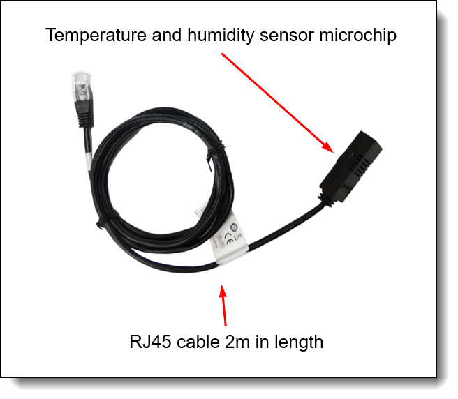
The optional PDU Environmental Temperature & Humidity sensor (part number 4XF7A93184) can be used to report local temperature and humidity values and make that information available to management tools. The EMP connects to the PDU via its NMC. The PDU Environmental Temperature & Humidity sensor is shown in the following figure.
Figure 10. Environmental Temperature & Humidity sensor
The Environmental Temperature & Humidity sensor has the following features:
- Shipped with 2 Meter cable and integrated magnet for easy mounting
- Hot pluggable for easy integration
- Temperature Measuring Range 0 to 65 °C
- Temperature Measuring Accuracy +/- 2 %
- Humidity Measuring Range 10-90% RH, Non-Condensing
- Humidity Measuring Accuracy +/- 5 %
- Can be extended with a standard Ethernet cable
Additional information. Using an Ethernet cable to extend the EMP has the following requirements / limitations :
- Requires: a cross-over Ethernet cable
- Supported cables: CAT 5E or CAT 6E 4Core cable
- Maximum length of the Ethernet cable that can be used: 30 m (98 ft)
Selecting the right PDU
To avoid over sizing or under sizing power, it is important to understand the power requirements of the hardware that will be powered by the PDU(s). A useful tool to leverage to help calculate overall power usage is the Lenovo Capacity Planner (LCP) https://datacentersupport.lenovo.com/us/en/solutions/lnvo-lcp.
Likewise, to avoid over sizing it is also important to understand the PDU capabilities and capacities.
Consider the following for capabilities:
- Do you require monitoring and/or outlet switching? If so, then consider the switched and monitored PDUs described here. If not, consider the Basic PDUs described above as well.
- Do you require environmental monitoring capabilities? If so, then consider the switched and monitored PDUs described here. If not, consider the Basic PDUs described above as well.
- Does the PDU have the right type of power for your scenario? For example, 16A, 30A, 32A, 63A and single or three phase power?
- Does the PDU have enough of the correct type of outlets for your scenario?
Consider the following for capacities:
- Will each outlet be able to support the load being connected to it? For example, C13 outlets have a 10A limit.
- Will each load group be able to support the hardware being connected to it?
- Will each phase, where applicable, be able to support the hardware being connected to it?
- Is the overall power capacity of the PDU able to support the hardware being connected to it?
- Do you have enough PDUs to be N+N or N+1 redundancy if this is required?
For additional information on selecting the right PDU, load groups, phases, outlets, line cords, plugs and specifications, reference tables above and/or vendor's nVent (CIS) site.
Supported rack cabinets
The 0U Switched and Monitored PDUs can be installed in the following racks:
- S2 42U Standard Rack cabinet (Types 9307)
- 42U 1200mm Deep Dynamic Rack (Type 9360)
- 42U 1200mm Deep Static Rack (Type 9361)
- 42U 1100mm Enterprise V2 Dynamic Rack (Type 9363)
- The 42U or 48U Heavy Duty Rack Cabinet (machine types 7D6D or 7D6E) are supported.
Enlogic PDUs are built with tool-less mounting in most rack enclosure designs.
These PDUs are designed to be mounted without the use of tools. Mounting buttons are pre-installed on the rear of the PDU at the factory. The mounting buttons allow for three mounting methods for installing the 0U Switched and Monitored PDUs vertically in a rack.
- Using factory-installed buttons on the PDU to mount the PDU in keyhole openings in the rack frame
For additional information on racking the 0U basic or Switched and Monitored PDUs, refer to User’s Guide for the PDUs.
Warranty
The Lenovo zero-U (0U) Basic and Switched and Monitored power distribution units (PDUs) are offered with a three-year limited warranty. At Lenovo discretion this warranty will be either CRU service (customer replaceable unit) or a Lenovo employee, subcontractor or reseller will be assigned to repair the failing item. Proof and date of purchase is required for warranty claims.
Agency approvals
The PDUs conform to the following standards:
- CE, Demko Certified to IEC/EN60950-1
- ROHS, REACH
Related publications and links
For more information, see the following documents:
- nVent Lenovo product age:
https://www.nvent.com/en-us/data-solutions/support/lenovo - Enlogic user manual basic PDUs:
https://enlogic.com/product/EB0337 - Enlogic user manual switched and monitored PDUs:
https://enlogic.com/product/EN6381 - Lenovo Capacity Planner (LCP):
https://datacentersupport.lenovo.com/us/en/solutions/lnvo-lcp
Trademarks
Lenovo and the Lenovo logo are trademarks or registered trademarks of Lenovo in the United States, other countries, or both. A current list of Lenovo trademarks is available on the Web at https://www.lenovo.com/us/en/legal/copytrade/.
The following terms are trademarks of Lenovo in the United States, other countries, or both:
Lenovo®
The following terms are trademarks of other companies:
Active Directory® and Georgia® are trademarks of Microsoft Corporation in the United States, other countries, or both.
Other company, product, or service names may be trademarks or service marks of others.
Configure and Buy
Full Change History
Changes in the August 21, 2025 update:
- Added the following under Related publications and links section
- nVent Lenovo product page
Changes in the July 18, 2025 update:
- Updated PDU tables to show GEO market as Y or N and also enable pop up window to show country support:
- Under Basic PDUs section
- Under Switched and Monitored PDUs section
Changes in the July 16, 2025 update:
- Removed the following withdrawn PDUs
- 4PU7A93170, 4PU7A93172, 4PU7A93173, 4PU7A93174
Changes in the March 17. 2025 update:
- Updated LA region support for the following PDU under Switched and Monitored PDUs section
- 0U 16 C13/C15 and 16 C13/C15/C19 Switched and Monitored 24A 1 Phase PDU(30A derated), 4PU7A93172
Changes in the August 30, 2024 update:
- Updated region support for Switched and Monitored v1 PDUs table under Switched and Monitored PDUs section
Changes in the August 14, 2024 update:
- Added new section for sensor under Environment Probe section
- Environmental Temperature & Humidity sensor
Changes in the July 19, 2024 update:
- Updated region support for the following PDUs under Basic PDUs section
- v1 Basic PDUs
- Updated region support for the following PDUs under Switched and Monitored PDUs section
- Switched and Monitored v1 PDUs
Changes in the June 25, 2024 update:
- Added the following new v2 PDUs under Basic PDUs section
- 0U 36 C13 and 6 C19 Basic 32A 1 Phase PDU v2, 4PU7A93176
- 0U 24 C13/C15 and 24 C13/C15/C19 Basic 32A 3 Phase WYE PDU v2, 4PU7A93177
- Added the following new v2 PDUs under Switched and Monitored PDUs section
- 0U 21 C13/C15 and 21 C13/C15/C19 Switched and Monitored 48A 3 Phase Delta PDU v2 (60A derated), 4PU7A93181
- 0U 20 C13 and 4 C19 Switched and Monitored 32A 1 Phase PDU v2, 4PU7A93178
- 0U 18 C13/C15 and 18 C13/C15/C19 Switched and Monitored 63A 3 Phase WYE PDU v2, 4PU7A93182
- 0U 18 C13/C15 and 18 C13/C15/C19 Switched and Monitored 32A 3 Phase WYE PDU v2, 4PU7A93180
- 0U 16 C13/C15 and 16 C13/C15/C19 Switched and Monitored 24A 1 Phase PDU v2 (30A derated), 4PU7A93179
Changes in the June 21, 2024 update:
- Updated three phase feature for the following table under Switched and Monitored PDUs section
- 0U 18 C13/C15 and 18 C13/C15/C19/C21 Switched and Monitored 32A 3 Phase WYE PDU, 4PU7A93173
Changes in the June 6, 2024 update:
- Updated region availability for the following table under Switched and Monitored PDUs section
- Switched and Monitored PDUs - Ordering part numbers and feature codes
Changes in the June 5, 2024 update:
- Updated region availability for the following under Switched and Monitored PDUs section
- 0U 16 C13/C15 and 16 C13/C15/C19 Switched and Monitored 24A 1 Phase PDU(30A derated), 4PU7A93172
- 0U 18 C13/C15 and 18 C13/C15/C19 Switched and Monitored 32A 3 Phase WYE PDU, 4PU7A93173
- Removed the following footnote for 4PU7A93174, 4PU7A93175
- Planned ship support for these PDUs is 2Q/2024
Changes in the April 24, 2024 update:
- Updated the following under Related publications and links section
- Lenovo Capacity Planner
- Updated the following under Selecting the right PDU section
- Lenovo Capacity Planner
- Updated feature code for basic and switched and monitored PDUs
Changes in the April 2, 2024 update:
- Updated details on the following under Features and specifications switched and monitored PDUs section
- 4PU7A93172
- 4PU7A93173
Changes in the March 21, 2024 update:
- Removed C21 outlet not supported for the following under Features and specifications switched and monitored PDUs section
- 4PU7A93173
- 4PU7A93175
Changes in the March 20, 2024 update:
- Updated table details under Features and specifications basic PDUs section
- Updated table details under Features and specifications switched and monitored PDUs section
First published: March 18, 2024
Course Detail
Employees Only Content
The content in this document with a is only visible to employees who are logged in. Logon using your Lenovo ITcode and password via Lenovo single-signon (SSO).
The author of the document has determined that this content is classified as Lenovo Internal and should not be normally be made available to people who are not employees or contractors. This includes partners, customers, and competitors. The reasons may vary and you should reach out to the authors of the document for clarification, if needed. Be cautious about sharing this content with others as it may contain sensitive information.
Any visitor to the Lenovo Press web site who is not logged on will not be able to see this employee-only content. This content is excluded from search engine indexes and will not appear in any search results.
For all users, including logged-in employees, this employee-only content does not appear in the PDF version of this document.
This functionality is cookie based. The web site will normally remember your login state between browser sessions, however, if you clear cookies at the end of a session or work in an Incognito/Private browser window, then you will need to log in each time.
If you have any questions about this feature of the Lenovo Press web, please email David Watts at dwatts@lenovo.com.


