

Top
Authors
Published
13 Aug 2024Form Number
LP2000PDF size
13 pages, 406 KBSubscribed to LP2000.
Thank you for your feedback.
Table of Contents
Abstract
Configuring a server with balanced memory is important for maximizing its memory bandwidth and overall performance. Lenovo ThinkSystem 2-socket servers running Intel 4th Gen and 5th Gen Xeon Scalable processors (formerly codenamed “Sapphire Rapids” and "Emerald Rapids", respectively) have eight memory channels per processor and up to two DIMM slots per channel, so it is important to understand what is considered a balanced configuration and what is not.
This paper defines three balanced memory guidelines that will guide you to select a balanced memory configuration. Balanced and unbalanced memory configurations are presented along with their relative measured memory bandwidths to show the effect of unbalanced memory. Suggestions are also provided on how to produce balanced memory configurations.
This paper is for customers and for business partners and sellers wishing to understand how to maximize the performance of Lenovo ThinkSystem 2-socket servers with 4th Gen or 5th Gen Intel Xeon Scalable processors.
Introduction
The memory subsystem is a key component of 4th and 5th Gen Intel Xeon Scalable server architecture which can greatly affect overall server performance. When properly configured, the memory subsystem can deliver extremely high memory bandwidth and low memory access latency. When the memory subsystem is incorrectly configured, memory bandwidth available to the server can become limited and overall server performance can be reduced.
This paper explains the concept of balanced memory configurations that yield the highest possible memory bandwidth from the 4th and 5th Intel Gen Xeon Scalable architectures. Memory configuration and performance for all supported memory configurations are shown and discussed to illustrate their effect on memory subsystem performance.
This paper specifically covers the 4th Gen and 5th Gen Intel Xeon Scalable processor families (formerly codenamed “Sapphire Rapids” and "Emerald Rapids", respectively). For other processor families, see the Balanced Memory papers section.
The Intel processors have four integrated Memory Controllers (iMC), eight memory channels, and sixteen memory DIMM slots. The following figure illustrates how the Intel processor’s memory controllers are connected to memory DIMM slots.
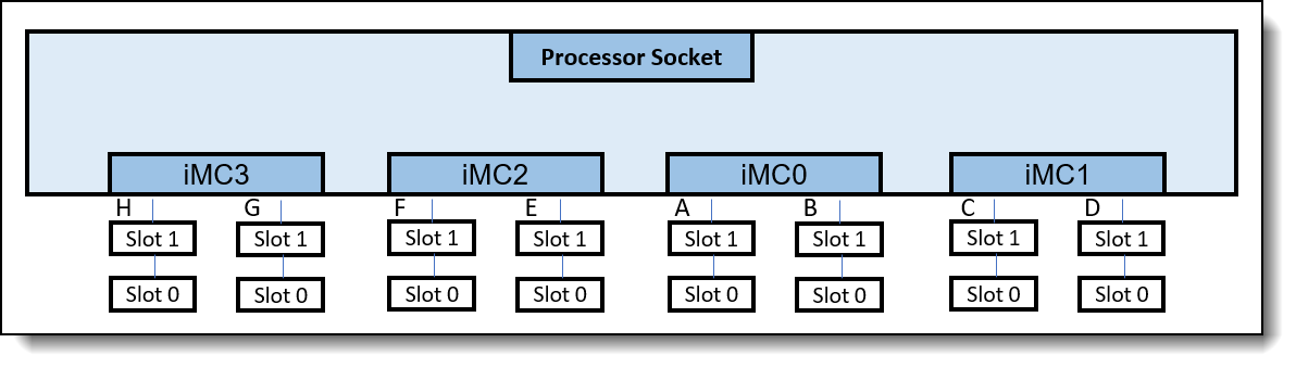
Figure 1. Memory DIMM connections to the Intel processor
Each integrated Memory Controller (iMC) supports two memory channels as below:
- iMC0 supports channels A and B
- iMC1 supports channels C and D
- iMC2 supports channels E and F
- iMC3 supports channels G and H
To illustrate various memory topologies for a processor, different memory configurations will be designated as H:G:F:E:A:B:C:D where each letter indicates the number of memory DIMMs populated on each memory channel. As an example, a 2:2:2:2:1:1:1:1 memory configuration has 2 memory DIMMs populated on channels H, G, F, E and 1 memory DIMM populated on channels A, B, C, D.
Memory interleaving
The 4th and 5th Gen Intel Xeon Scalable processors optimize memory accesses by creating interleave sets across the memory controllers and memory channels. For example, if two memory channels have the same total memory capacity, a 2-channel interleave set is created across the memory channels.
Interleaving enables higher memory bandwidth by spreading contiguous memory accesses across more memory channels rather than sending all memory accesses to one memory channel. In order to form an interleave set between two channels, the two channels are required to have the same channel memory capacity.
If one interleave set cannot be formed for a particular memory configuration, it is possible to have multiple interleave sets. When this happens, performance of a specific memory access depends on which memory region is being accessed and how many memory DIMMs comprise the interleave set. For this reason, memory bandwidth performance on memory configurations with multiple interleave sets can be inconsistent. Contiguous memory accesses to a memory region with fewer channels in the interleave set will have lower performance compared to accesses to a memory region with more channels in the interleave set.
Figure 2 illustrates a 4-channel interleave set which results from populating identical memory DIMMs on channels A, C, E, G. This 4-channel interleave set interleaves across memory controllers and between memory channels. Consecutive addresses alternate between memory controllers with every fourth address going to each memory channel.
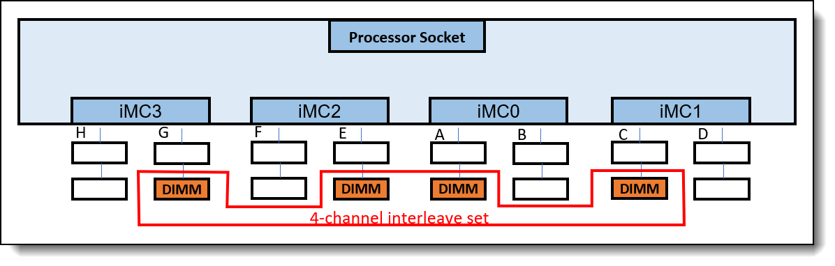
Figure 2. 4-channel interleave set across memory controllers and between memory channels
Balanced memory configurations
Balanced memory configurations enable optimal interleaving which maximizes memory bandwidth. Per Intel memory population rules, channels A, E, C, G must be populated with the same total capacity per channel if populated, and channels B, D, F, H must be populated with the same total capacity per channel if populated.
The basic guidelines for a balanced memory subsystem are as follows:
- All populated memory channels should have the same total memory capacity and the same number of ranks per channel.
- All memory controllers on a processor socket should have the same configuration of memory DIMMs.
- All processor sockets on the same physical server should have the same configuration of memory DIMMs.
Tip: We will refer to the above guidelines as Balanced Memory Guidelines 1, 2 and 3 throughout this paper.
About the tests
Intel Memory Latency Checker (Intel MLC) is a tool used to measure memory latencies and bandwidth. The intent of the tool is to measure the highest memory bandwidth available. Intel MLC will be used to measure the sustained memory bandwidth of various memory configurations supported by 4th and 5th Gen Intel Xeon Scalable processors.
All one DIMM per channel and two DIMMs per channel configurations were measured at the following Intel plan of record memory speeds for regular RDIMMs:
- 4th Generation Intel Xeon “Sapphire Rapids”
- One DIMM per channel – 4800MHz
- Two DIMMs per channel – 4400MHz
- 5th Generation Intel Xeon “Emerald Rapids”
- One DIMM per channel – 5600MHz
- Two DIMMs per channel – 4400MHz
For more information about Intel MLC, see the following web page:
https://www.intel.com/content/www/us/en/developer/articles/tool/intelr-memory-latency-checker.html
Applying the balanced memory configuration guidelines
We will start with the assumption that balanced memory guideline 3 (as listed in Balanced memory configurations) is followed: all processor sockets on the same physical server have the same configuration of memory DIMMs. Therefore, we only have to look at one processor socket to describe each memory configuration.
For a complete memory rules and population guide, please refer to the Lenovo Press product guide for each specific ThinkSystem V3 server that uses the 4th and 5th Gen processors.
In our lab measurements, all memory DIMMs used were 32GB dual-rank (2R) RDIMMs. The examples in this brief follow the recommended memory population sequence as shown in the following table.
Tip: Some ThinkSystem V3 servers only implement 1 DIMM per channel. Take that into consideration when reviewing the memory recommendations.
Configuration with 1 DIMM – unbalanced
We will start with one memory DIMM which yields the 0:0:0:0:1:0:0:0 memory configuration shown in the figure below.
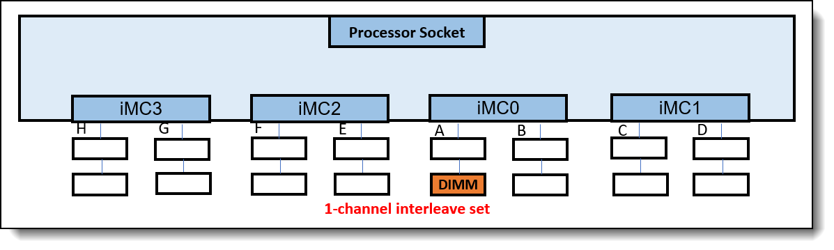
Figure 3. 0:0:0:0:1:0:0:0 memory configuration, relative memory bandwidth: 13%
Balanced memory guideline 2 is not followed with only one iMC populated with memory DIMM. This is an unbalanced memory configuration.
A single 1-channel interleave set is formed. Having only one memory channel populated with memory greatly reduces the memory bandwidth of this configuration which was measured at 13% or about one eighth of the full potential memory bandwidth.
The best way to increase the memory bandwidth of this configuration is by using more memory DIMMs. For example, two 16GB RDIMMs populated on two channels A and G would provide the same memory capacity while nearly doubling the memory bandwidth.
Configuration with 2 DIMMs – unbalanced
The recommended memory configuration with 2 memory DIMMs is the 0:1:0:0:1:0:0:0 configuration as shown in the following figure.
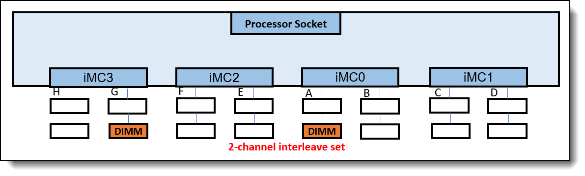
Figure 4. 0:1:0:0:1:0:0:0 memory configuration, relative memory bandwidth: 25%
This memory configuration follows guideline 1, but not guideline 2 since not all iMCs were populated with identical memory configuration. This is an unbalanced memory configuration.
A single 2-channel interleave set is formed. Only two memory channels are populated with memory which greatly reduces the memory bandwidth of this memory configuration to about 25% or one fourth of the full potential memory bandwidth.
Configuration with 4 DIMMs – balanced
The recommended configuration with 4 memory DIMMs is 0:1:0:1:1:0:1:0 memory config as shown in the following figure.
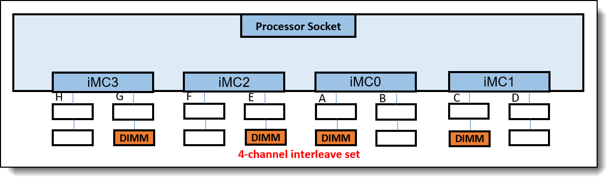
Figure 5. 0:1:0:1:1:0:1:0 memory configuration, relative memory bandwidth: 50%
This memory configuration follows both memory population guidelines 1 and 2. All populated channels have the same channel capacity, and memory configurations are identical with all iMCs. This is a balanced memory configuration.
A single 4-channel interleave set is formed. Although it is a balanced memory configuration, only four of eight memory channels were populated with memory DIMMs. Memory bandwidth is measured at 50% or one half of the full potential memory bandwidth.
Configuration with 6 DIMMs – unbalanced
The recommended configuration with 6 memory DIMMs is 1:1:0:1:1:1:1:0 memory configuration as shown in the follwoing figure.
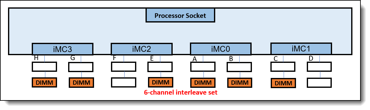
Figure 6. 1:1:0:1:1:1:1:0 memory configuration, relative memory bandwidth: 75%
This memory configuration follows memory population guideline 1, but not guideline 2. Memory configurations are not identical between the iMCs. This is an unbalanced memory configuration.
A single 6-channel interleave is formed, and memory bandwidth measured at 75% of the full potential memory bandwidth. Even though a 6 DIMM population is unbalanced, the 4th and 5th Gen Intel Xeon Scalable processor design includes the technology to create a single 6-channel interleave which results in relatively good performance. Without this technology, multiple interleave sets would have been formed and performance would be degraded.
Configuration with 8 DIMMs – balanced
The recommended configuration with 8 DIMMs is 1:1:1:1:1:1:1:1 memory configuration as shown in the following figure.
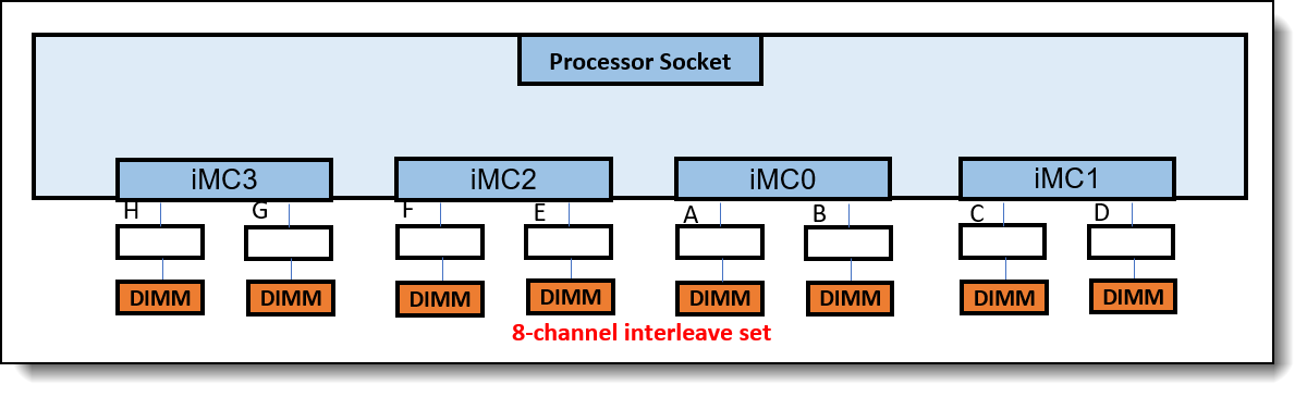
Figure 7. 1:1:1:1:1:1:1:1 memory configuration, relative memory bandwidth: 100%
This memory configuration follows both guidelines 1 and 2. All channels were populated with the same memory capacity, and memory configurations were identical between all iMCs. This is a balanced memory configuration.
A single 8-channel interleave is formed, and memory bandwidth measured at 100% of the full potential memory bandwidth.
Configuration with 12 DIMMs – unbalanced
The recommended configuration with 12 DIMMs is 1:2:1:2:2:1:2:1 memory configuration as shown in the following figure.
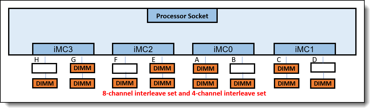
Figure 8. 1:2:1:2:2:1:2:1 memory configuration, relative memory bandwidth: 50-85% with SPR and 50-75% with EMR
This memory configuration follows guideline 2, but not guideline 1. This is an unbalanced memory configuration.
One 8-channel interleave and one 4-channel interleave set is formed, and memory bandwidth measured at 50% - 85% of the full potential memory bandwidth for 4th Gen (Sapphire Rapids) processors, and 50% - 75% of the full potential memory bandwidth for 5th Gen (Emerald Rapids) processors. The lower than potential bandwidth is the result of not utilizing all eight memory channels and the Intel supported memory speeds when memory is configured with two DIMMs per channel.
Configuration with 16 DIMMs – balanced
This is a fully populated configuration 2:2:2:2:2:2:2:2 as shown in the following figure.
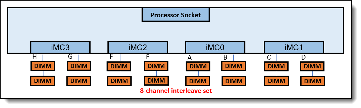
Figure 9. 2:2:2:2:2:2:2:2 memory configuration, relative memory bandwidth: 85% with SPR and 76% with EMR
This is a fully populated memory configuration. It follows both guideline 1 and 2. This is a balanced memory configuration.
Each channel is populated with two dual-rank (2R) DIMMs, so the total number of ranks per channel is 4R. Memory bandwidth measured at 85% with SPR, and 76% with EMR of the full potential memory bandwidth due to the memory speed dropping with two DIMMs per channel as per Intel plan of record.
Summary of the performance results
The following table shows a summary of the relative memory bandwidth of all the memory configurations that were evaluated. It also shows the number of interleave sets formed for each and whether it is a balanced or unbalanced memory configuration.
When using the same memory DIMM, only a memory configuration with 8 DIMMs provides the full potential memory bandwidth. This is the best memory configuration for performance. A balanced memory configuration can also be achieved with four memory DIMMs, but this configuration does not populate all the memory channels which reduces its memory bandwidth and performance. Finally, a balanced memory configuration can also be achieved with 16 memory DIMMs, although this requires two DIMMs per channel which drops the memory speed as per Intel’s plan of record.
Maximizing memory bandwidth
To maximize the memory bandwidth of a server, the following rules should be followed:
- Balance the memory across the processor sockets – all processor sockets on the same physical server should have the same configuration of memory DIMMs.
- Balance the memory across the memory controllers – all memory controllers on a processor socket should have the same configuration of memory DIMMs.
- Balance the memory across the populated memory channels – all populated memory channels should have the same total memory capacity and the same total number of ranks.
Peak memory performance is achieved with 8 DIMMs per socket. Given a memory capacity requirement per server, follow these steps to get an optimal memory bandwidth configuration for your requirement:
- Determine your needed memory capacity per socket.
- Divide this memory capacity by eight to determine the minimum memory capacity needed per DDR channel.
- Round this calculated memory capacity per channel up to the closest capacity available with 1 DIMM Per Channel (DPC)
- Populate your server with eight identical DIMM combination per channel derived from step 3.
Examples:
- If 512GB of total memory capacity is needed per socket, you can populate each socket with 8x 64GB DIMMs.
- If 768GB of total memory capacity is needed per socket, you can populate each socket with 8x 96GB DIMMs.
Summary
Overall server performance is affected by the memory subsystem which can provide both high memory bandwidth and low memory access latency when properly configured. Balancing memory across the memory controllers and the memory channels produces memory configurations which can efficiently interleave memory references among its DIMMs producing the highest possible memory bandwidth. An unbalanced memory configuration can reduce the total memory bandwidth to as low as 13% of a balanced memory configuration with 8 identical DIMMs installed per processor.
Implementing all three of the balanced memory guidelines described in this paper results in balanced memory configuration and produces the best possible memory bandwidth and overall performance.
Lenovo recommends installing balanced memory population with 4, 8, or 16 DIMMs per socket. Peak memory performance is achieved with 8 DIMMs per processor.
Authors
This paper was produced by the following team of specialists:
Charles Stephan is a Senior Engineer and Technical Lead for the System Performance Verification team in the Lenovo Performance Laboratory at the Lenovo Infrastructure Solutions Group (ISG) campus in Morrisville, NC. His team is responsible for analyzing the performance of storage adapters, network adapters, various flash technologies, and complete x86 platforms. Before transitioning to Lenovo, Charles spent 16 years at IBM as a Performance Engineer analyzing storage subsystem performance of RAID adapters, Fibre Channel HBAs, and storage servers for all x86 platforms. He also analyzed performance of x86 rack systems, blades, and compute nodes. Charles holds a Master of Science degree in Computer Information Systems from the Florida Institute of Technology.
Redwan Rahman is a Systems Performance Verification Engineer in the Lenovo Infrastructure Solutions Group Performance Laboratory in Morrisville, NC, USA. His current role includes CPU, Memory, and PCIe subsystem analysis and performance validation against functional specifications and vendor targets. Redwan holds a Bachelor of Science in Computer Engineering from University of Massachusetts Amherst.
Thanks to the following people for their contributions to this project:
- David Watts, Lenovo Press
This paper was based on the paper Balanced Memory Configurations for 2-Socket Servers with 3rd-Gen Intel Xeon Scalable Processors. Thanks to the author of that paper:
- Nathan Pham
Balanced Memory papers
This paper is one of a series of papers on Balanced Memory configurations:
Intel processor-based servers:
- Balanced Memory Configurations for 2-Socket Servers with Intel Xeon 6 Processors
- Balanced Memory Configurations for 2-Socket Servers with 4th and 5th Gen Intel Xeon Scalable Processors
- Balanced Memory Configurations for 2-Socket Servers with 3rd Gen Intel Xeon Scalable Processors
- Balanced Memory Configurations with 2nd Gen Intel Xeon Scalable Processors
- Balanced Memory Configurations with 1st Generation Intel Xeon Scalable Processors
- Maximizing System x and ThinkServer Performance with a Balanced Memory Configuration
AMD processor-based servers:
Trademarks
Lenovo and the Lenovo logo are trademarks or registered trademarks of Lenovo in the United States, other countries, or both. A current list of Lenovo trademarks is available on the Web at https://www.lenovo.com/us/en/legal/copytrade/.
The following terms are trademarks of Lenovo in the United States, other countries, or both:
Lenovo®
System x®
ThinkServer®
ThinkSystem®
The following terms are trademarks of other companies:
AMD and AMD EPYC™ are trademarks of Advanced Micro Devices, Inc.
Intel®, the Intel logo and Xeon® are trademarks of Intel Corporation or its subsidiaries.
Other company, product, or service names may be trademarks or service marks of others.
Configure and Buy
Please select a locale
Full Change History
Course Detail
Employees Only Content
The content in this document with a is only visible to employees who are logged in. Logon using your Lenovo ITcode and password via Lenovo single-signon (SSO).
The author of the document has determined that this content is classified as Lenovo Internal and should not be normally be made available to people who are not employees or contractors. This includes partners, customers, and competitors. The reasons may vary and you should reach out to the authors of the document for clarification, if needed. Be cautious about sharing this content with others as it may contain sensitive information.
Any visitor to the Lenovo Press web site who is not logged on will not be able to see this employee-only content. This content is excluded from search engine indexes and will not appear in any search results.
For all users, including logged-in employees, this employee-only content does not appear in the PDF version of this document.
This functionality is cookie based. The web site will normally remember your login state between browser sessions, however, if you clear cookies at the end of a session or work in an Incognito/Private browser window, then you will need to log in each time.
If you have any questions about this feature of the Lenovo Press web, please email David Watts at dwatts@lenovo.com.


