

Top
Authors
Published
24 Jun 2025Form Number
LP2234PDF size
67 pages, 10.6 MBSubscribed to LP2234.
Thank you for your feedback.
Table of Contents
Abstract
This paper offers guidance on examining the system RAS (Reliability, Availability, and Serviceability) design of Lenovo ThinkSystem from the perspective of running a Linux operating system. It aims to ensure that memory RAS functions properly on our systems, encompassing hardware, UEFI firmware, Linux OS, and Lenovo BMC.
This paper is for Linux administrators who wish to test memory RAS in a ThinkSystem server and to analyze Linux OS logs to determine if memory hardware errors have occurred on the system. All the setups are based on RHEL 9.6 with kernel 5.14.0-552.el9 running on a ThinkSystem SR850 V4 server with Intel Xeon 6 P-core processors.
Introduction
Servers are a crucial component of modern data center infrastructure, comprising processors, memory, PCIe devices, power supplies, and fans, with the primary requirement being continuous operation without compromising data integrity, whether data is stored in components like memory, cache, or registers or transmitted through platform links.
To meet these demands, Reliability, Availability, and Serviceability (RAS) features maximize server availability and preserve data integrity by focusing on three key objectives:
- Extending system uptime through enhanced reliability metrics
- Minimizing unplanned downtime via rapid fault identification and repair
- Containing faults to prevent data corruption spread
Memory RAS testing on Lenovo ThinkSystem servers is central to achieving these goals, validating error detection, component compatibility, failure prediction, redundancy mechanisms, and diagnostic capabilities to proactively identify hardware issues, verify redundant components, and optimize maintenance - all critical for maintaining high availability and minimizing downtime in enterprise environments where even brief outages can have severe consequences.
As technology evolves, the demand for systems that can operate seamlessly under various conditions has become paramount.
This paper examines the system RAS (Reliability, Availability, and Serviceability) design of Lenovo ThinkSystem SR860 V4 server with Intel Xeon 6 P-core processors, from the perspective of running a Linux operating system. It aims to ensure that memory RAS functions properly on our systems, encompassing hardware, UEFI firmware, Linux OS, and the Lenovo XClarity Controller BMC.
RAS Enabling Framework
The figure below depicts the entire RAS Enabling Framework. It encompasses the three RAS value vectors mentioned earlier:
- Extending System Uptime (which contributes to system reliability and enhances fault tolerance)
- Minimizing Unplanned Downtime (which contributes to system serviceability and maintainability)
- Fault Containment (which maintains data integrity)
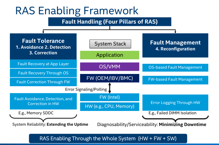
Figure 1. RAS Enabling Framework (from Intel Document ID #575370)
The framework also outlines the four pillars of RAS fault handling: Avoidance, Detection, Correction, and Reconfiguration.
These pillars are classified into two categories:
- Fault Tolerance, which aims to extend the system's uptime.
- Fault Management, which focuses on minimizing the system's downtime.
Both RAS categories permeate through the hardware (HW), firmware (FW), operating system/virtual machine monitor (OS/VMM), and applications, ensuring comprehensive and integrated RAS capabilities across all levels of the system.
The fundamental pillars are as follows:
- Fault Avoidance
Chipset vendor employs circuits, circuit margins, and advanced design techniques to prevent faults from occurring in the first place. By carefully engineering these aspects, the aim is to minimize the likelihood of any issues arising within the system.
- Fault Identification
If a fault does occur, rapid identification is crucial. Upon detecting an error, identify the failed FRU the first time, quickly and reliably, e.g., error logging and signaling as close to the source of the fault. Lenovo ThinkSystem provides hardware logging mechanisms that can be utilized by higher software layers. These mechanisms enable the software to detect the fault and initiate remedial actions promptly.
- Correction and Recovery
Once a fault has been correctly identified, Lenovo ThinkSystem offers mechanisms to correct the fault and facilitate system recovery. These mechanisms are designed to address the issue effectively, ensuring that the system can resume normal operation as quickly as possible.
- Correct the faults using various HW techniques, such as Error Correction Code (ECC), CRC retry, and Instruction Retry.
- Recover from uncorrected faults using various SW techniques, such as MCA recovery and PCI Express Live Error Recovery.
- Reconfiguration
To the appropriate extent, the system should be capable of self-reconfiguration around the fault. Even in the presence of impairments, this allows the system to recover from the fault and continue operating. By adapting its configuration, the system can bypass the affected areas and maintain functionality, thereby enhancing overall reliability and availability.
Software Architecture
Thanks to the corresponding kernel driver offering interfaces, the details of the hardware errors and software architecture are transparent to user applications. However, some knowledge of the underlying hardware and software is helpful for performance optimization and debugging.
The following figure shows a brief view of Linux OS based server RAS implementation.
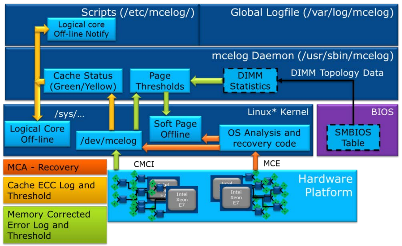
Figure 2. Linux Operating System Error Handling Flow (from Intel Document ID#563361: Purley Platform RAS Technology Integration and Validation Guide)
Hardware faults are reported to the OS through either MCE (Machine Check Exception) or CMCI (Corrected Machine Check Interrupt). There are other mechanisms existing for notifying error events, such as SCI (System Control Interrupt) and NMI (Non-Maskable Interrupt).
MCA Recovery feature implementation uses MCE to notify the OS when an SRAR or SRAO (‘Software Recoverable Action Required’ or ‘Software Recoverable Action Option’) type of event is detected by the hardware.
The OS analyses the log and verifies if recovery is feasible. It then takes the affected page (default is a 4KB page) offline and logs the event in the ‘mcelog’.
- In the case of an SRAO-type event, the OS recovers and resumes the normal execution.
- In the case of an SRAR-IFU (Instruction Fetch Unit) type event, the OS reloads the 4KB page containing the instruction to a new physical page and resumes normal execution.
- In the case of an SRAR-DCU (Data Cache Unit) type event, the OS triggers a ‘SIGBUS’ event to notify the application of further recovery action.
The application has a choice to either reload the data and resumes normal execution or kill the application without crashing the entire system.
EMCA1 vs EMCA2 Mode
The Intel Xeon Processor E7-v3 first introduced the Enhanced Machine Check Architecture Gen 2 (EMCA2). As an RAS feature, it redirects Machine Check Exceptions (MCE) and Corrected Machine Check Interrupts (CMCI) to the firmware via System Management Interrupt (SMI) before sending them to the OS error handler. This enables BIOS-based error recovery.
When EMCA2 is enabled, the BIOS can configure each MC (machine check) bank to trigger an SMI instead of an MCE or CMCI. Before an MCE or CMCI is signaled, a specific SMI is triggered, allowing the BIOS System Management Mode (SMM) handler to correct the error if possible. On Intel Xeon Processor E7-v3, the BIOS SMM handler can also access data in each MC bank, including IA32_MCi_STATUS, IA32_MCi_ADDR, and IA32_MCi_MISC.
Prior to the Enhanced Machine Check Architecture (EMCA), the IA32-legacy Machine Check Architecture (MCA) implemented error handling by logging all errors in architected registers (MC banks) and signaling them to the OS or Virtual Machine Monitor (VMM).
However, this legacy version had limited capabilities in platform firmware for fault diagnosis and isolating Field Replaceable Units (FRUs), such as DIMMs and PCI Express devices. It also faced several constraints in OS-based error handling:
- Uncorrected errors (UCE) had to be routed to the Non-Maskable Interrupt (NMI), but the NMI handler might fail to contain the fault effectively.
- The NMI mechanism prevents error recovery, even though some MCEs could be recoverable.
- Reporting Uncorrectable No Action (UCNA) errors via System Control Interrupt (SCI) may not be fast enough. If the “MCA Error Control” (Cloaking) is enabled, CMCI can be used for signaling.
- Some error logs are restricted from being accessed at the BIOS/firmware level, which limits the OS-based error handling capabilities. For example, certain error logs or registers are stored in Control and Status Register (CSR) or Model-Specific Register (MSR) shadow registers that OS/VMM may not fully access.
Due to these shortcomings in the legacy MCA error handling mechanism, EMCA1 was developed. It allows the firmware to handle, collect, and build enhanced error logs before reporting them to the system software. This enables the system software to obtain more comprehensive error logs for making better error recovery decisions.
Once the EMCA1-associated registers and signaling plans are set, the BIOS SMM handler collects MC Bank registers and other model-specific error logging registers. For corrected errors, an SMI is sent to the BIOS/SMM handler for initial error handling before a CMCI is signaled to the system OS. For uncorrected errors, both an SMI and MCERR are triggered simultaneously.
EMCA2 further enhances the firmware first model in error handling, especially with the Enhanced System Management Mode (Enhanced SMM). Enhanced SMM offers new features such as Directed SMI, in-silicon SMM state saving, an extended SMM memory range register (SMRR2), and SMM security. With EMCA2, the SMM handler can now read from and write to machine check banks, unlike in EMCA1, where it was read only. For uncorrected errors, a Machine System Management Interrupt (MSMI) is triggered first, followed by MCERR after the SMM handler exits.
Beyond the First Firmware Model (FFM), EMCA2 enables the firmware to provide additional error information to the system software through the ACPI Device-Specific Method (DSM) and an enhanced MCA L1 directory data structure, in synchronization with MCE or CMCI. The following two figures compare the signaling flows and error handling details between EMCA1 and EMCA2.
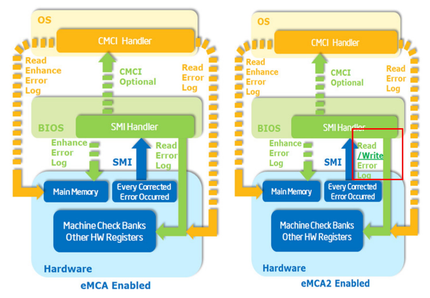
Figure 3. EMCA1 and EMCA2 Corrected Error Signaling Flow Comparison
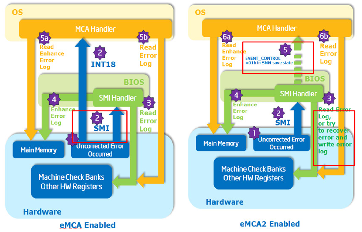
Figure 4. EMCA1 and EMCA2 Uncorrected Error Signaling Flow Comparison
The EMCA2’s Error Handling with FFM is shown in the figure below. The responsibilities of each main component are as follows.
- CPU:
- CE: Trigger SMI for Firmware First Mode and CMCI for OS Native Mode.
- UCE: Trigger SMI for Firmware First Mode and MCE for OS Native Mode.
- BIOS/FW:
- CE: Populate Enhanced Error Log and trigger CMCI while RSM (Resume) or Populate WHEA/GHES and trigger SCI while RSM for page retirement.
- UCE: Populate Enhanced Error Log and trigger MCE while RSM or Populate WHEA/GHES and trigger NMI while RSM.
- OS/VMM:
- CE: Page retirement flow for Firmware First Mode or CEC (Correct Error Count) for OS Native Mode.
- UCE: Page retirement and recovery flow for application, and might panic for kernel space.
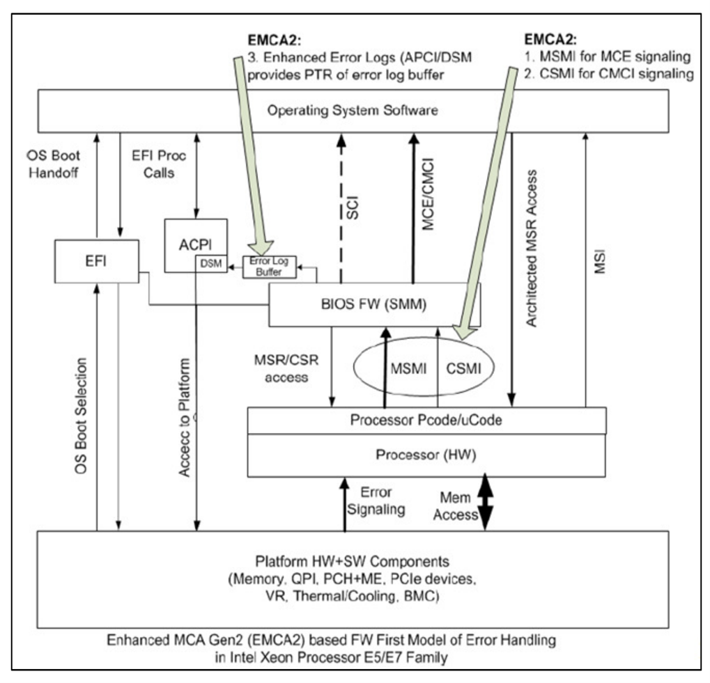
Figure 5. Firmware First Model EMCA2 Error Handling (from Intel Document ID #563361)
Note: If MCA Bank Error Control is enabled and Elog is not enabled, it will be the responsibility of the BIOS to provide mem physical address info to the OS via the ACPI method.
New designs on Lenovo ThinkSystem V4
The Lenovo ThinkSystem V4 platform introduces several architectural enhancements to improve error handling, system reliability, and cross-OS compatibility. These innovations build upon previous generations while introducing new mechanisms such as Enhanced Error Logging (Elog) and immediate OS notification for UCNA errors.
Use Elog to notify errors
Error logging is a critical component of modern server platforms, enabling proactive fault diagnosis and recovery. The ThinkSystem V4 platform adopts Enhanced Error Log (Elog), a BIOS-driven mechanism that provides a structured, memory-resident error log for the OS. Unlike traditional methods like WHEA (Windows Hardware Error Architecture), Elog offers improved synchronization with Machine Check Architecture (MCA) events, streamlined error reporting, and support for predictive failure analysis.
The definition of Elog
Within the EMCA1/2 architecture, Enhanced Error Log (Elog) is a capability of the BIOS to present error logs to the OS in an architectural manner using a data structure located within the main memory, as shown in the following figure.
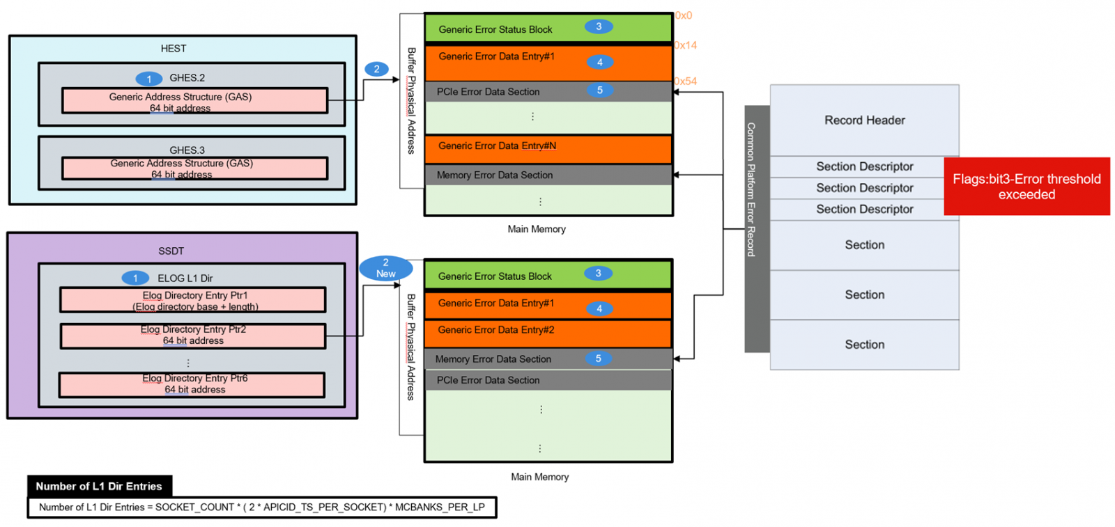
Figure 6. ACPI WHEA/GHES table and Elog table Comparison
OS can traverse the data structures that are pointed to by EXTENDED_MCG_PTR MSR and locate the Enhanced Error Log.
The memory range used for error logs is pre-allocated and reserved by FW during boot time. This allows the OS to provide the correct mapping for this range. These memory buffers cannot be part of SMRAM since the OS cannot read SMRAM. This range must be 4K aligned and may be located below or above 4 GB.
UEFI follows ACPI Spec to provide ACPI DSM (Device Specific Method). DSM is a control method that enables devices to provide device-specific control functions that the device driver consumes. It indicates that enhanced MCA Logging is implemented and will return 64-bit enhanced MCA L1 Directory Address as shown in the figure below. The address must be 4k aligned and point to firmware reserved memory.
The following figure shows ACPI Generic ELog Directory with ACPI Generic Error Data Entry. Refer to ACPI Spec for the description of each block. The OS can get the physical address from ACPI DSM and the link to Directory. In EMCA L1 Directory, all entry point addresses represent physical addresses of the corresponding valid ACPI Generic Error Status Block Structure (4KB aligned).
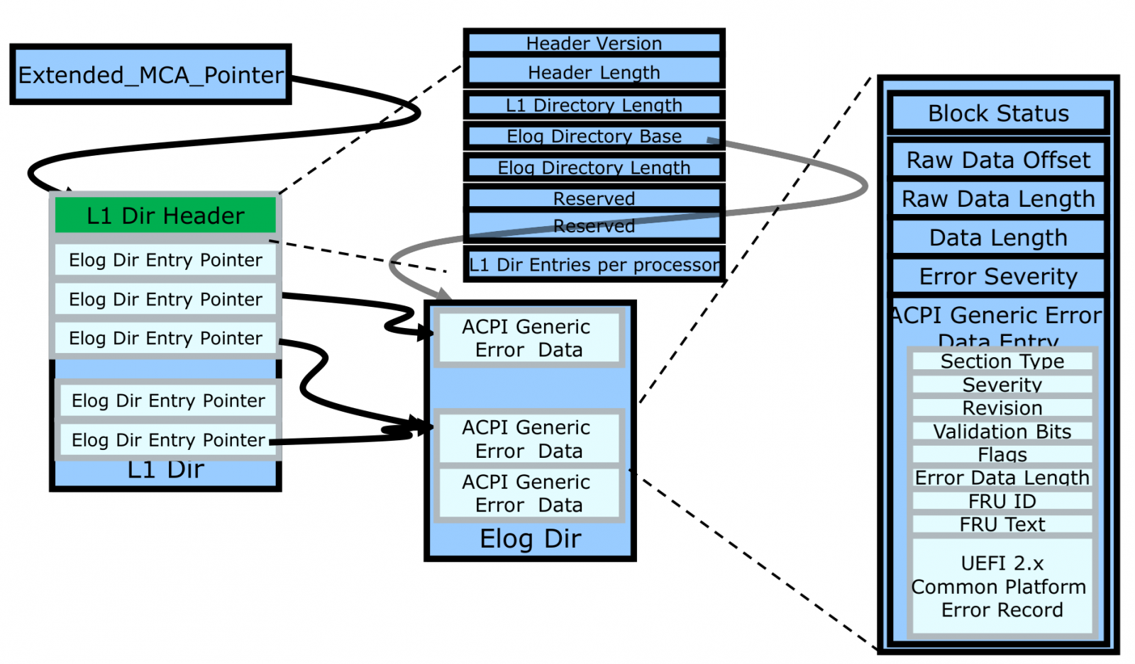
Figure 7. Enhanced Error Log Data Structure (from Intel Document ID #517321)
The advantages of using Elog
The use of Elog has the following advantages:
- In Legacy MCA mode, all faults (CE, UCR, UCE) are signaled to the OS directly. In EMCA1/2 enabled systems, those faults are routed through BIOS/SMM. BIOS/SMM is the first, and the OS is the second level of error handling, so use cases based on the OS that require BIOS-to-OS error log reporting can access platform-specific details.
- The existing ACPI/SCI infrastructure for reporting corrected errors would work fine when EMCA1/2 is enabled. But it has shortcomings in handling UCE/UCR errors when EMCA1/2 is enabled:
- UCE would require routing through NMI, which is not desirable by the OS. In some cases, the OS continues operating even after NMI and may lose fault containment.
- NMI precludes error recovery. On the other hand, OS/VMM could leverage existing infrastructure if the error is signaled as a recoverable MCE.
- UCNA error reporting via SCI may not be fast enough. If ‘MCA Error Control’ (Cloaking) is enabled, then CMCI cannot be leveraged.
- Using the Elog method, a single interrupt (CMCI or MCE) sent to the OS allows it to read both the MCA bank information and the supplementary information stored in the Elog by the platform. In contrast, the NMI and SCI sent by the WHEA in ACPI/SCI can only acquire the supplementary information filled in by UEFI in SMM.
- Elog directly calculates the corresponding position of the Generic Error Status Block based on the CPU and MCA bank number, as shown in the preceding figure above. After finding the correct position, it reads the values inside for subsequent analysis, instead of mapping, scanning, and making judgments on the memory during interrupts like the WHEA in ACPI/SCI.
- The OS parses the flags set by UEFI in the Generic Error Data Entry of the Generic Error Status Block added in the Elog shown as the preceding figure above, and then performs the page retirement operation to achieve the effect of Predictive Failure Analysis (PFA). In this way, it can rely on the parameters passed by UEFI to perform page retirement, just like the WHEA in ACPI/SCI.
The flows of Elog on Lenovo ThinkSystem V4
ThinkSystem V4 is based on the Intel Birch Stream platform.
There are two types of error logging mechanisms: Elog (Enhanced Error Log) and WHEA (Windows Hardware Error Architecture) logging. The Elog Directory is a contiguous data structure that contains several entries, each of which is in the form of a CPER log. Elog complements machine check bank contents synchronous with MCE/CMCI.
Note: WHEA (old legacy naming) is also known as APEI GHES (ACPI Platform Error Interfaces Generic Hardware Error Status) or UEFI CPER (Unified Extensible Firmware Interface Common Platform Error Record).
Regarding EMCA2 signaling plans, CMCI (Corrected Machine Check Interrupt) morphs to CSMI (Corrected System Management Interrupt), and MCE (Machine Check Exception) morphs to MSMI (Machine System Management Interrupt). In this case, every correctable error triggers CSMI, and every uncorrected error triggers MSMI.
Once a CSMI or MSMI is signaled, the system will enter the SMM (System Management Mode) handler. The firmware can then access the MSR (Model-Specific Register) or CSR (Control and Status Register) error log registers to conduct the initial level of error identification and handling. Instead of using the WHEA (Windows Hardware Error Architecture) log, all relevant information is logged into the Elog. For Elog, once reporting to the OS, the SMM handler builds the L1 enhanced error log prior to RSM, then triggers the OS-level error signals, such as CMCI, MCE, or SCI, for further error diagnosis or recovery in the OS Machine Check handler.
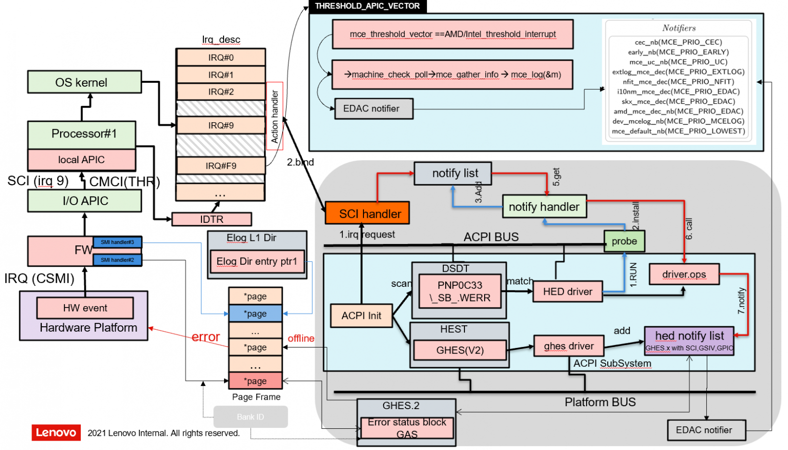
On Lenovo ThinkSystem V4, which is similar to Lenovo's previous generation platforms, both correctable errors and UCNA (Uncorrectable No Action) events still collect information and send it to WHEA/GHES. However, when an uncorrectable error or a fatal error occurs, the register information is copied to the Elog. Instead of using SCI/NMI as in the previous platform, the system then uses the MCE (Machine Check Exception) interrupt to notify the OS. Subsequently, the Elog data will be parsed by a notifier named extlog_mce_dec(), referring to the following figure.
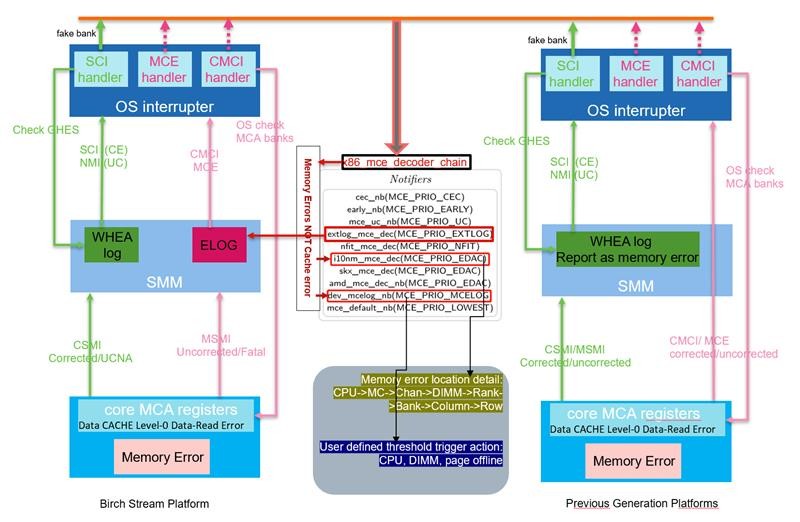
Figure 8. Comparison between Lenovo ThinkSystem V4 and previous generation platforms
Notify OS immediately when UCNA occurs
On Lenovo's previous generation platforms, UCNA (Uncorrectable No Action) errors were not handled and reported to the OS immediately from UEFI. However, on the Birch Stream platform, the goal is to trigger the page offline as soon as a UCNA error occurs. To achieve this, UEFI is designed to notify the OS using the SCI interrupt with a pre-filled ACPI WHEA table, following the preceding figure.
Furthermore, to accommodate different OS behaviors, such as ESXi proactively consuming and clearing data from the uncore MCA bank, whereas Linux does not. To ensure consistent behavior across operating systems, Lenovo uses CSMI to report the occurrence of a UCNA to UEFI.
From the OS perspective, when a UCNA error happens, it still aims to trigger the OS's page retirement function. Thus, after a UCNA error, UEFI sends an SCI (System Control Interrupt) to the OS, expecting the OS to successfully carry out the page retire process, so that different OS can have the same behavior while UCNA occurred.
RAS in Linux OS
Linux exists in hundreds of distinct distributions provided by OS Vendors, each with its own schedule for integrating updates from the upstream kernel at kernel.org. In this context on Lenovo ThinkSystem SR850 V4 with Intel Birch Stream platform, the focus is mainly on major enterprise-class distributors: Red Hat (covering RHEL 9.4 and higher versions), SUSE (including SLES15 SP6 and higher, as well as SLES15.6), Ubuntu (including Ubuntu 24.04) and the upstream kernel version 6.4.0 and higher.
Over the years, the error reporting capabilities of the Linux operating system have undergone significant evolution and improvement.
The following are the primary error reporting mechanisms in Linux:
MCELOG
The Linux kernel gathers information from groups of registers called machine check banks. This data and related contextual details like processors that logged errors and timestamps, are transmitted to the MCELOG (8) daemon process through a special device file, /dev/mcelog. The daemon performs both X86 architectural decoding and limited model-specific decoding of this information to pinpoint the error source as precisely as possible. For instance, architectural data from the machine check banks can identify the processor socket and memory channel in case of a memory error.
Moreover, the daemon can be configured to take actions and send notifications when error rates surpass configurable thresholds. That means mcelog can set memory pages offline when a certain configured error threshold is exceeded and offers the opportunity to extend its operation using a trigger script. For example, if there are more than ten correctable errors within 24 hours defined in the script, the daemon will instruct the kernel to take a memory page offline and stop using it.
For more in-depth details, visit http://mcelog.org/.
EDAC
Linux also supports Error Detection and Correction (EDAC) drivers, which supply additional platform-specific information. Given the necessity to read Control and Status Registers (CSR) that vary across different generations, each platform usually has its own dedicated EDAC driver.
EDAC drivers meet two key requirements of market segments, such as High-Performance Computing (HPC) and Cloud Computing, where large machine clusters are prevalent:
- Reliable Memory Topology Description
They offer a dependable topological description of the memory components within each node. This includes details about the size, speed, and type of Dual In-line Memory Modules (DIMMs) in each slot. Such information enables operators to verify that all performance interleaving and Reliability, Availability, and Serviceability (RAS) modes are activated.
- Precise Error Source Identification
When errors are detected, EDAC drivers can decode the reported system addresses back to the exact DIMM that caused the error. This significantly enhances the serviceability of the system.
The Linux Kernel incorporates an EDAC driver designed for the Intel and AMD platforms.
Upstream kernel 6.10 has integrated a commit that sets to ghes edac driver priority of the chipset-specific edac driver, so there are three methods to decode errors, the default order of the priority is the ghes edac driver, chipset-specified edac driver, and UEFI DSM (\\_SB.ADXL). Of course, each method can be applied in Linux OS individually by appending the corresponding kernel parameters.
As the EDAC (Error Detection and Correction) technology continues to evolve, for the latest and detailed changes as of the time of writing this paper, for example, for the upstream kernel version v6.13, refer to the documentation at https://www.kernel.org/doc/html/v6.13/driver-api/edac.html
FTrace
Linux FTrace can monitor multiple kernel tracepoints related to events, such as Machine Check Architecture (MCA) issues, PCI Express Advanced Error Reporting (PCIe AER) events, and memory failures. By default, FTrace is installed on most Linux distributions. For a fundamental guide on using FTrace, see https://www.kernel.org/doc/Documentation/trace/ftrace.txt.
Rasdaemon
Rasdaemon consolidates different approaches to monitoring hardware and reading sensors. Rasdaemon can also hand out vendor-specific information to match hardware issues to real hardware, i.e., motherboard labels matching EDAC entries. If these exist for certain hardware where an issue is seen, one can see the direct DIMM name instead of generic information, such as a memory error in the DIMM.
The initial goal of rasdaemon is to replace the edac-tools that got bit-flipped after the addition of HERM (Hardware Events Report Method) was added to the EDAC Kernel drivers.
The long-term goal is to be the userspace tool that will collect all hardware error events reported by the Linux Kernel from several sources (EDAC, MCE, PCI, etc.) into one common framework. Instead of developing a new EDAC (Error Detection and Correction) driver for each platform generation, Linux can gather extended error logs in UEFI format from platforms with the EMCA (Enhanced Machine Check Architecture) feature enabled. By default, this information is just logged to the system console. However, a new application named “rasdaemon” has emerged. It collects and organizes this information, and optionally stores the logs in an SQLite database. This database allows users to query the data and analyze patterns within the reported errors.
Rasdaemon also provides a utility “ras-mc-ctl”, which can perform the following tasks:
- Register motherboard DIMM labels into EDAC driver sysfs files. It uses the detected mainboard manufacturer and model number in combination with a "labels database" found in any of the files under /etc/ras/dimm_labels.d/* or in the labels.db file at /etc/ras/dimm_labels.db.
- Shows the errors stored in the error database. The file is stored in /var/lib/rasdaemon/ras-mc_event.db based on SQLite. Before rasdaemon starts,the content of the file is empty, and after starting rasdaemon, the file contains tables like mc_event, mce_record that come from the linux OS FTrace file in the raw trace debugfs node /sys/kernel/debug/tracing/per_cpu/cpu*/trace_pipe_raw.s.
- The ras-mc-ctl uses the following methods to determine the current system's mainboard vendor and model information:
- If the config file /etc/edac/mainboard exists, then it is parsed by ras-mc-ctl.
- If the mainboard config file does not exist, then ras-mc-ctl will attempt to read DMI information from the sysfs files:
- /sys/class/dmi/id/board_vendor
- /sys/class/dmi/id/board_name
- If the sysfs file mentioned above does not exist, then ras-mc-ctl will parse the output of dmidecode.
Ubuntu 24.04 uses rasdaemon as a default checking application, while RHEL and SLSE use mcelog as an application to check errors. However, while also shipping mcelog, rasdaemon was integrated from RHEL9.6. Mcelog operates through the /dev/mcelog interface, whereas rasdaemon captures kernel trace events.
For more information on how to use rasdaemon, see: https://github.com/mchehab/rasdaemon/blob/master/README.md.
EINJ
Error Injection (EINJ) injects errors through software, which is useful for debugging and testing ACPI Platform Error Interface (APEI) and general RAS features. This paper is based on this tool for testing. See https://www.kernel.org/doc/Documentation/acpi/apei/einj.txt for a basic guide on EINJ.
Besides the EINJ test tool, there are a bunch of other tools that could be used in different scenarios. A brief introduction is listed below.
- Out of Band CScripts. The Scripts with ITPII is based on the Intel DFX technology built on Intel silicon to provide injections and validations.
- In-band CScripts. The Scripts is based on the ACPI EINJ table or on-die registers to provide run-time error injections and validations at the OS level.
- Windows Based WHEAHCT Tool. The tool is part of the Win HCK kit for Windows-based error injection utility used in MCA recovery features validation.
- AMEI Tool. Asynchronous Machine-check Error Injection (AMEI) provides the capability to verify UEFI FW and SW-based error handlers by implanting errors within the various machine-check banks and then triggering CMCI/MCERR/MSMI/CSMI events.
- MEI/DTC Tool. MEI provides methods to directly pull up/down physical data or address the bit line to inject the following DDR4 DIMM errors. The DTC tool provides methods to inject errors into the Intel Optane persistent memory.
- PCI Express HW EINJ Tools. A variety of PCI Express HW EINJ cards are available that provide the PCIe error injection capabilities. Examples of such cards include the Intel PCIe Gen4 EINJ card and toolkit, KeysightTM Exerciser card, and Variety of OxM-developed proprietary PCIe Error injector cards.
- Autonomous Crash-Dump (ACD). Autonomous Crash-Dump (ACD) is the out-of-band method to collect the Crash-record. The BMC autonomously detects a failure; use the BMC to collect the Crash-record, and the BMC will generate a standardized format file.
Error injection validates a system’s capabilities. When appropriate error injection methods are employed, the system's error handling and recovery mechanisms can be effectively validated according to the RAS configurations and the memory operation mode settings. The error recovery capability depends on the selected RAS modes and the proper programming of specific control and signaling registers.
Suitable validation tools are utilized to conduct error injection in different modules. The user guides of these tools offer valuable references for each command and use case scenario.
Linux-based DebugFS Tool
RAS validation tools are required to inject various types of errors, create an appropriate workload, and monitor the system behaviors and error logs.
The following validation tools are recommended for system RAS features validation:
- CScripts and In-band CScripts (Intel RDC document number 572261)
- OS/EINJ-based utilities (example: Linux DebugFS, Win HCK)
- AMEI Tool
- MEI/DTC Tool
- PCI Express* HW Error Injector Card
- Memory stress tools such as PTU, Memtest86r, and MLC
On Linux OS, Linux-based DebugFS Tool is an excellent set of tools to inject and test RAS functionality on X86 and ARM platforms through the APEI EINJ interface. When the Linux environment is ready, download the Linux tool through the following link: https://git.kernel.org/pub/scm/linux/kernel/git/aegl/ras-tools.git
This link is a Linux-based debugFS Tool, which is a Linux-based error injection utility used in PFA feature validation, MCA recovery features validation, and memory mirror feature validation. It has the following abilities.
- Ability to inject a correctable error in the execution path.
- Ability to inject an SRAO type of error in the non-execution path, such as a patrol scrub error.
- Ability to inject an SRAR type of error in the execution path, including DCU and IFU errors.
- Ability to consume and recover the error using pseudo application codes.
The tool includes Intel-developed pseudo applications “mca-recover” and “einj_mem_uc”, which implements the SIGBUS handler to proceed SRAR, SRAO, and UCNA types of error injection and recovery validations.
The “mca-recover” utility can proceed with the following actions:
- Inject UCR-SRAR DCU or IFU error type (0x10) through ACPI EINJ Table.
- Allocate memory, perform simple computation, and provide virtual page to physical page mapping. This physical page address is then used by the error injection tool to be injected an uncorrected recoverable error to.
- Consume and label the errors as SRAR-type errors.
- Notify SRAR-type errors by the SIGBUS handler, which has been set up by the tool and perform recovery.
The “einj_mem_uc” utility can perform the following actions:
- Inject uncorrectable non-fatal errors (error type 0x10) through ACPI EINJ Table.
- Consume data immediately in DCU and label the errors as SRAR-type errors.
Note: On Lenovo ThinkSystem V4 Platform, the utility “mca-recover” can only trigger UCNA with UEFI, starting to expose UCNA to the upper layer OS on the Birch Stream platform. In the test of “mca-recover”, the error of the physical address is consumed in the IMC uncore bank and triggers UCNA to take the page offline. Since the test case does not consume data immediately, the data is not loaded to DCU to trigger SRAR. In this situation, the OS takes the error page offline but doesn’t send SIGBUS to the application until the application accesses the virtual address and triggers a page fault. The SIGBUS will kill “mca-recover” due to the hardware memory corruption. But since “einj_mem_uc” consumes data immediately, it triggers SRAR in the DCU core bank and sends SIGBUS to kill “einj_mem_uc”. The details will be demonstrated in the MCA Recovery Feature Validation Recipe section.
Applications should be designed to handle SIGBUS signals. The following is an example of SIGBUS handler API code, which is needed as part of the target application.
 /*
 * "Recover" from the error by allocating a new page and mapping
 * it at the same virtual address as the page we lost. Fill with
 * the same (trivial) contents.
 */
void memory_error_recover (int sig, siginfo_t *si, void *v)
{
        struct morebits *m = (struct morebits *)&si->si_addr;
        char    *newbuf;

        printf("recover: sig=%d si=%p v=%p\n", sig, si, v);
        printf("Platform memory error at 0x%p\n", si->si_addr);
        printf("addr = %p lsb=%d\n", m->addr, m->lsb);
// allocate page and map at lost address
        newbuf = mmap(buf, pagesize, PROT_READ|PROT_WRITE|PROT_EXEC, MAP_FIXED|MAP_ANONYMOUS|MAP_PRIVATE, -1, 0);
        if (newbuf == MAP_FAILED) {
                fprintf(stderr, "Can't get a single page of memory!\n");
                exit(1);
        }
        if (newbuf != buf) {
                fprintf(stderr, "Could not allocate at original virtual address\n");
                exit(1);
        }
		// keep virtual address as same as original
        buf = newbuf;
        // memset(buf, '*', pagesize);
        phys = vtop((unsigned long long)buf);

        printf("Recovery allocated new page at physical %llx\n", phys);
}

struct sigaction recover_act = {
.sa_sigaction = memory_error_recover,
.sa_flags = SA_SIGINFO,
};
main(...)
{
sigaction(SIGBUS, &recover_act, NULL);
...
if (sigsetjmp(...)) {
// recovery happened
}
// main loop
while (get_work())
do_work();
}
Set up RAS in UEFI
If you are using the ACPI/EINJ table on the OS, ensure that the following configurations are applied on your server platform.
- Before you set up RAS, it’s better for you to load the default settings in UEFI.
- In System Setup (F1 at boot), enter the UEFI System Configuration and Boot Management.
- From the UEFI setup menu path, select Load Default Settings.
- Now you can continue to set up RAS following Step 2.
- Enable Machine Check Recovery (Enabled by default) in the UEFI settings.
- From the UEFI setup menu path, select System Settings → Recovery and RAS → Advanced RAS → Machine Check Recovery to enable it as shown in the following figure.
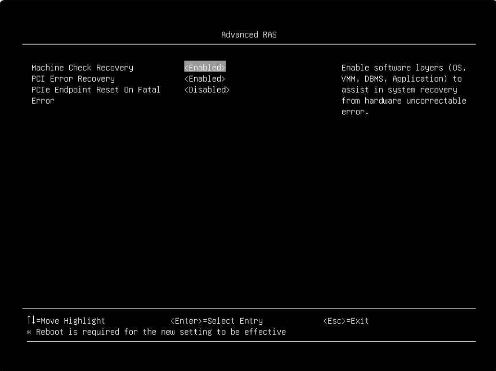
Figure 9. The Machine Check Recovery Setting in the UEFI setup menu - After enabling Machine Check Recovery, save and exit the System Setup menu, and then boot the Linux OS.
- From the UEFI setup menu path, select System Settings → Recovery and RAS → Advanced RAS → Machine Check Recovery to enable it as shown in the following figure.
- Use the OneCLI tool to enable more UEFI options.
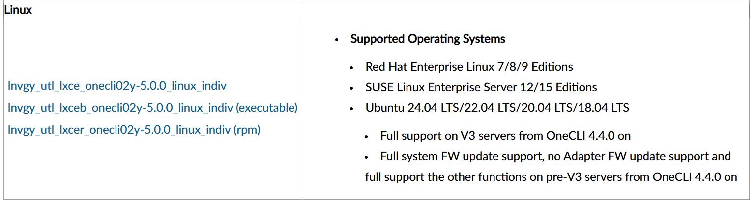
- Download the OneCLI tool from http://support.lenovo.com/us/en/documents/lnvo-tcli.
For example, you can download the rpm package to your server platform.
- Install the OneCLI tool.
For example, you can install it using the command “yum install xxx.rpm”.
- Set configurations using commands as follows. Among them, <user>, <passwd>, and <ip> are BMC’s username, password, and IP address, separately.
onecli config set BIOS.AdvancedRAS_MachineCheckRecovery "Enabled" --override --imm <user>:<passwd>@<ip>
onecli config set BIOS.AdvancedRAS_DisableBIOSDone "true" --override --imm <user>:<passwd>@<ip>
onecli config set BIOS.AdvancedRAS_MSRLockControl "Disabled" --override --imm <user>:<passwd>@<ip>
onecli config set BIOS.Memory_WHEAErrorInjectionSupport "Enabled"  --override --imm <user>:<passwd>@<ip>
onecli config set BIOS.Memory_McaBankErrorInjectionSupport "Enabled"  --override --imm <user>:<passwd>@<ip>
onecli config set BIOS.Memory_CorrectableErrorThreshold 2 --override --imm <user>:<passwd>@<ip>
onecli config set BIOS.Memory_PatrolScrubInterval  24 --override --imm <user>:<passwd>@<ip>
onecli config set BIOS.AdvancedRAS_EVDFXFeatures "Enabled" --override --imm <user>:<passwd>@<ip>
onecli config set BIOS.AdvancedRAS_LockChipset "Enabled" --override --imm <user>:<passwd>@<ip>
onecli config set BIOS.SystemOobCustom_PFATest "Enabled" --override --imm <user>:<passwd>@<ip>
- Download the OneCLI tool from http://support.lenovo.com/us/en/documents/lnvo-tcli.
- Restart the server, and now all configurations are applied.
Introduction to Memory RAS Test Cases
The RAS validation recipes described below in this document are based on RHEL 9.6. The following configurations should be set by default in RHEL 9.6. However, if you encounter errors in your test, please check if the following configurations are correct. “make menuconfig” can be used to open GUI for this check.
CONFIG_X86_MCE=y
CONFIG_X86_MCE_INTEL=y
CONFIG_ACPI_APEI=y
CONFIG_ACPI_APEI_GHES=y
CONFIG_ACPI_APEI_MEMORY_FAILURE=y
CONFIG_X86_MCE_INTEL=m
CONFIG_MEMORY_FAILURE=y
CONFIG_ACPI_APEI_EINJ=m or CONFIG_ACPI_APEI_EINJ=y
The test cases covered in this document are the following:
Testing PFA for Correctable Errors
This section validates the end-to-end Predictive Failure Analysis (PFA) workflow for memory correctable errors, from threshold detection to OS-level page retirement, covering UEFI-initiated retirement scenarios, Linux offline page handling requirements, and the complete validation methodology using error injection tools to verify proper system response when correctable error thresholds are exceeded.
In this section:
Page Retirement Mechanism Overview
The memory page retirement mechanism is the core function of Predictive Failure Analysis (PFA), ensuring system stability by isolating faulty memory pages. When a single memory page accumulates excessive correctable errors, UEFI collaborates with the operating system to mark the faulty page as retired status, preventing its continued use. This mechanism involves key technical aspects including hardware error monitoring, firmware-OS communication, and multi-level cache consistency maintenance.
- Memory Page (4KB) Retire Operation
The Memory Page (4KB) Retire Operation is a crucial mechanism that enhances system reliability by managing memory pages with excessive correctable errors. This operation leverages the ACPI feature integrated into UEFI to communicate with the OS, ensuring seamless coordination in handling faulty memory pages.
- Communication and Page Retirement
When a memory page accumulates a significant number of correctable memory errors, the ACPI-UEFI communication channel signals the OS. This prompts the OS to stop using the affected page, effectively retiring it. However, this action can only be taken when the memory is not locked by a critical process or application. Once the Page Retire operation is successfully completed, future errors related to this page will no longer be recorded in the system hardware log. Nevertheless, the OS logs will retain these entries for diagnostic purposes.
- Cache Invalidation after Retirement
After the OS confirms to the platform that a specific memory page range has been successfully retired, it takes the necessary steps to ensure that the retired memory range is flushed and invalidated across all caching agents. These agents include I/O device caches, processor caches, Translation Lookaside Buffers (TLBs), and chipset tables or caches such as VT-D or IOMMU. As a result, the OS will not access this memory page in the OS runtime phase, preventing potential issues caused by faulty memory.
- Lenovo ThinkSystem UEFI's Support
Lenovo ThinkSystem UEFI plays a vital role in supporting the page retirement mechanism. It creates a dedicated Generic Hardware Error Source Structure (GHESS) specifically for page retirement requests. This structure is activated even before the OS boots and is registered in the Hardware Error Source Table (HEST) as per the ACPI specification.
- Initiating the Page Retirement Request and Processing Flow
When the number of correctable errors on a single memory page exceeds the predefined threshold, UEFI initiates a page retirement request to the OS. It does this by using the SCI (System Control Interrupt) method to notify the OS Power Management (OSPM). Additionally, UEFI conveys the specific address of the failing page through the WHEA/GHES table. If the OS can handle page retirement requests from UEFI, it will proceed to retire or take the failing memory page offline, safeguarding the system's stability and performance. The whole flow and related components of PFA are listed in the following figure.
- OS Compatibility for Page Retirement Requests
Numerous Operating System versions offer support for page retirement requests originating from UEFI. For instance, kernel 3.12 or later and VMware with ESXi 7.0U3/7.0.3 or later are among the compatible systems. It includes RHEL 8.x, 9.x, and 10.x, SLES 12.x, 15.x, and 16.x, Ubuntu 20.04.x, 22.04.x, 24.04.x, and so on. To obtain detailed information regarding OS compatibility and page retire support, it is advisable to contact your respective OS vendors.
- Predicted Failure Analysis (PFA) in ThinkSystem UEFI
ThinkSystem UEFI incorporates a Predicted Failure Analysis (PFA) mechanism for page retirement requests. It monitors specific thresholds related to these requests. If multiple page retirement requests exceed the established Page Retire PFA thresholds, UEFI generates a Page Retire PFA System Event Log (SEL) event, identified as FQXSFMA0057G (older UEFI versions use FQXSFMA0012L) for the affected DIMM.
PFA and Page Retirement
A single correctable error (CE) occurring in a memory chip can be detected and corrected by the system. Common causes for such errors include abnormal contact of the memory module's gold fingers, transmission issues, unstable voltage, and internal hardware damage, among others.
Page retirement issued to the OS by UEFI includes three scenarios:
- The number of single-bit Correctable Errors (CEs) exceeds the predefined upper limit.
A Correctable Memory Error (Memory CE) is a scenario where, during a cache line read operation by the CPU, data inversion occurs on only one memory device chip. In this case, the Error Checking and Correction (ECC) mechanism successfully verifies the data and corrects it. Once this happens, the system starts recording the error count. The System Management Interrupt (SMI) will be triggered only when the error count reaches the pre-set threshold. Lenovo ThinkSystem UEFI has two different level thresholds, one is a short-term threshold for a very short time window and the other is a long-term threshold for a long-term window. Then UEFI sends a page retirement request to the OS when those two conditions are met.
Three notes about correctable errors:
- Silicon hardware-based RAS features, such as ADDDC SR/MR, etc. will be utilized before reporting to UEFI to record error count.
- Lenovo ThinkSystem UEFI also sets a leak bucket value for DIMM of different memory vendors to drop some CEs intentionally.
- By default, Lenovo ThinkSystem UEFI is set to Firmware First Mode (FFM) and adheres to the aforementioned rules. In OS First Mode, a component called the Correctable Error Collector (CEC) is tasked with recording correctable errors within the Linux kernel. Additionally, there is a threshold value for page retirement. Notably, in OS First Mode, the same threshold value for page retirement is applied to all memory brands.
- Multi-Bit Correctable Error (Multi-Bit CE) occurs when the number of inverted bits on a single memory chip exceeds 2 but is less than the total number of data bits that the memory chip contributes to the cache line. In this situation, the system will trigger SMI, and the page retirement mechanism will be directly triggered the affected page offline.
- An Uncorrectable Memory Error (Memory UE) occurs when the CPU performs a cache line read operation and data inversion happens on two or more memory device chips, resulting in a failure of the Error Checking and Correction (ECC) verification. Once this situation occurs, the system will immediately trigger a System Management Interrupt (SMI) to UEFI, and UEFI will send an MCE interrupt to notify the OS to retire the error page.
Page retirement will trigger PFA to report a System Event Log (SEL) to BMC via the Lenovo ThinkSystem UEFI. Therefore, when checking the BMC Web GUI or SEL log, a message similar to the following should be displayed:
Page Retire PFA Threshold limit exceeded on DIMM 10 at address 0x000000496C5FD980.-T2 80CE01240905FAEADF-VC10-FRU 03LE907
The template is:
FQXSFMA0057G: Page Retire PFA Threshold limit exceeded on DIMM [arg1] at address [arg2].[arg3][arg4]
The meanings of those “arg” parameters in the output are shown below. For more output details, see https://pubs.lenovo.com/sr630-v4/FQXSFMA0057G.
- [arg1] DIMM Silk Label, 1-baseds
- [arg2] Address of the system where error occurred
- [arg3] Page retire PFA policy reached, "-T0";"-T1";"-T2";"-T3";"-T4".
- [arg4] DIMM info (S/N, FRU and UDI.), e.g. "739E68ED-VC10 FRU 0123456"
Contact the author for the meaning of T0-T4 if needed.
When a PFA is triggered, it means that the number of page retirements has exceeded one of the above thresholds. Once a page is taken offline, the corresponding row or column in the DIMM where the error occurred will no longer be utilized. Lenovo suggests users take the following actions while BMC receives the PFA warning message:
- Reseat the affected DIMM.
- Check the Lenovo Support site for an applicable service bulletin or firmware update that applies to this memory error.
- Swap the DIMM to another known good location.
- If the problem persists, collect Service Data logs and contact Lenovo Support.
If correctable errors (CE) continue to occur without any repairs being made, it may lead to uncorrectable errors (UE). Therefore, it is recommended that customers take prompt action.
Note: Triggering the Page Retirement does not necessarily result in a Predicted Failure Analysis (PFA). Reporting a PFA System Event Log (SEL) to BMC still requires meeting other criteria. For instance, even if the PFA threshold is reached and the OS has completed the page offline operation, the system will not report a PFA SEL if a Post Package Repair (PPR) request entry already exists in the DIMM.
An SEL log including PPR is like:
PLAT0140 DIMM 11 Self-healing, attempt post package repair (PPR) succeeded. 80CE01240805F7197C-VC10-FRU 03LE907
The UEFI log that shows “skipped reporting SEL” is like:
[MEM]DIMM 11(N0.C01.D0): [ErrorIsInPprVar] Address-Socket[0].MC[1].CH[1].D[0].SC[1].R[1].SR[0].B[27].Row[0x2100].FailDevMask = 0x80. Page Retire PFA Threshold limit (Policy -T3) exceeded at system address 0x0000001910926D40, skipped reporting SEL.
And the OS log will show the physical address of the offline page: 0x0000001910926d40
UEFI doesn’t know whether the OS has completed the page retirement process or when it will be finished. Therefore, after UEFI sends a page retirement request to the OS, it sets a specific period. During this period, any subsequent page retirement requests will be put on the pending list and will not be sent to the OS temporarily. Thus, you cannot see those corresponding CEs in the OS dmesg log, but PFA SEL is logged on the BMC side. Note that SEL only shows the latest pending one, while the OS dmesg only shows the first one it received before those pending errors. For example:
BMC SEL log shows:
WARNING 01/17/2025 09:35:11.816 Page Retire PFA Threshold limit exceeded on DIMM 10 at address 0x000000496C5FD980.-T2 80CE01240905FAEADF-VC10-FRU 03LE907
Dmesg shows:
[MEM]DIMM 10(N0.C05.D0): PageRetire is handled at system address 0x000000484D20AFC0, DRAM17, logical R0, SC0 SR0, B11(BG2, BA3), Row 0x5FFC, Col 0x2B0.
The one at address 0x000000484D20AFC0 received by the OS is the first one of the bunches of multi-CEs, with other multi-CEs pending there.
Pages Eligible for Offline Removal in the Linux OS
When UEFI sends "page retirement" to the Linux OS, you would not expect that the kernel dmesg will show keywords like “soft offline” for retiring successfully. Actually, it would be better for us to check whether the value of cat /proc/meminfo | grep HardwareCorrupted has increased and combine the UEFI and OS logs to ensure the page taken offline is successful or not.
Note that not all pages can be taken offline. The following conditions need to be met:
- The page is online - Only online pages can be soft-offlined (not ZONE_DEVICE).
- The page has not been corrupted yet, so it is still valid for access.
- The page is a free buddy page or a free hugetlbfs page.
- The page is not race with allocation at that point of time.
- If a page meets all the following conditions simultaneously: non-movable, not in the Least Recently Used (LRU) list, and not a hugetlbfs page, attempt to move it to the LRU list or release it to the buddy allocator (for example, by draining the slab or per-CPU page).
- If the page is in a transparent huge page, split the huge page first and then perform the page offline.
Notes:
- If the page is a non-dirty unmapped page-cache page, it will simply be invalidated and taken offline. It's the only circumstance that the keyword "soft_offline" is shown for successfully taking a page offline.
- If the page is mapped, the contents will be migrated, and some keywords like "soft offline" will show up when the migration or the isolation fails.
The function page_handle_poison() is charged for taking the final page offline, and it will call SetPageHWPoison(page) to set the page to be poisoned and call num_poisoned_pages_inc() to increase the value of HardwareCorrupted under /proc/meminfo.
PFA Feature Validation Recipe
This topic describes the methodology recommended for validating correctable errors to reach the PFA threshold and then trigger a page offline. Error injection tools and libraries, data collectors, and analyzers are the key components described here. The main goal is to verify the entire process, from injecting a hardware error to successfully handling it by the OS and BMC.
- Set up RAS in UEFI. For detailed steps, see the Set up RAS in UEFI section.
- Enable the DCI (Direct Connect interface) function. Enabling DCI enables us to inject and access reserved addresses, such as the EINJ table in ACPI. Please consult Lenovo for specific steps.
- Disable CEC (Collect Error Count) on the OS. Since UEFI has already set the correctable error threshold, disabling CEC is necessary in the OS. It not only disables kernel accounting for correctable errors but also allows mcelog and Elog to output to the OS log.
- Restart the system.
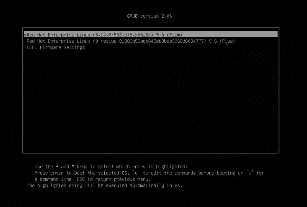
- When you see the grub interface, select the entry you want to enter, and press “e” to edit the commands when it is highlighted as follows.
- Append “ras=cec_disable” to the kernel parameter as shown below.
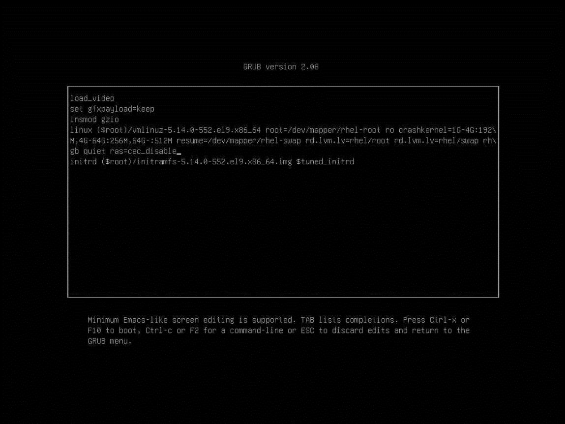
Figure 13. The grub interface to append the kernel parameter - Press Ctrl-X or F10 to boot to OS.
- Ensure that it is appended by “cat /proc/cmdline” after startup. The screenshot is shown below.
- Run mcelog and rasdaemon services for logging.
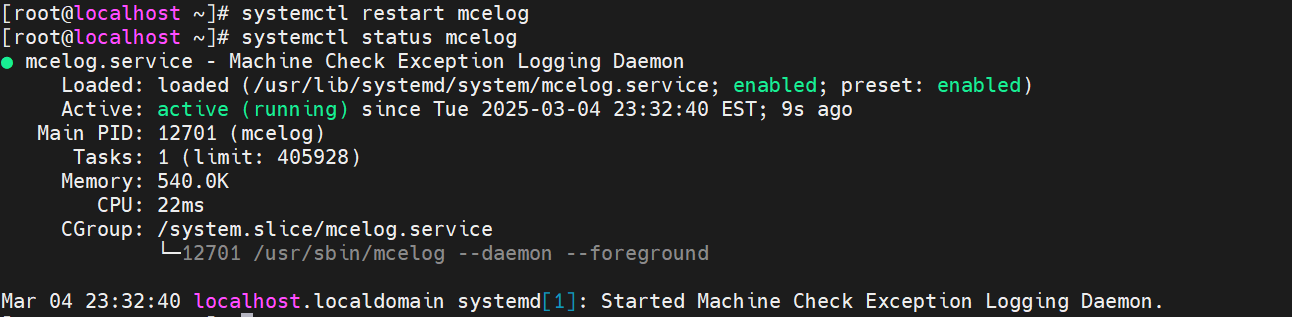
- Install mcelog using the command “yum install mcelog”, restart it, and ensure that the mcelog service is running when you are validating. For most RHEL OSes, the mcelog service is installed by default, so just check if it is running. Perform the command “systemctl status mcelog” to check the mcelog status, the output should indicate “active (running)”, see the following example. If it isn’t “active (running)”, execute “systemctl restart mcelog” and check again.
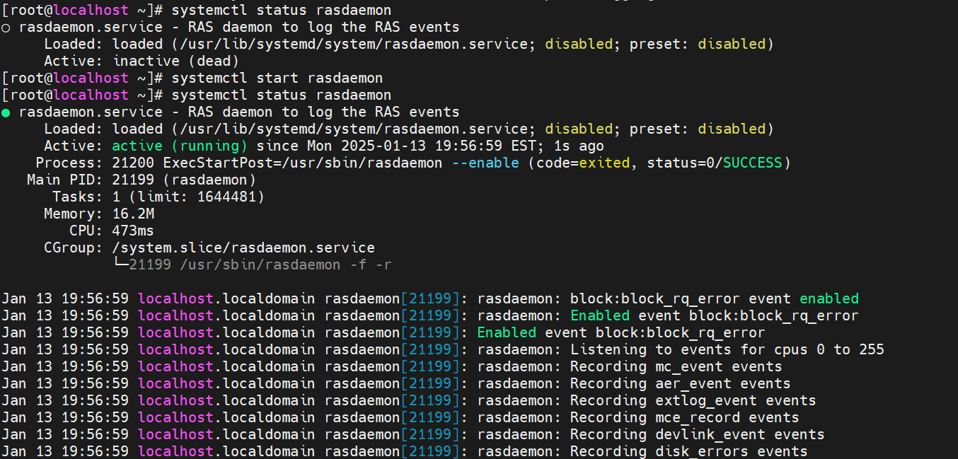
- Check the rasdaemon service in the same way.
- Load the module acpi_extlog and check whether it is loaded as follows.
- Download, extract, and compile the Linux-based DebugFS Tool.
Download it at https://git.kernel.org/pub/scm/linux/kernel/git/aegl/ras-tools.git. More details of this tool are described in the Linux-based DebugFS Tool section.
After downloading it, go to the directory ras-tool-master and use the make command to compile the tools.
The commands are as follows:
# wget https://web.git.kernel.org/pub/scm/linux/kernel/git/aegl/ras-tools.git/snapshot/ras-tools-master.tar.gz # tar -xvf ras-tool-master.tar.gz # cd ras-tools-master # make - After compiling the tool, several executable binary files will be generated, including “mca-recover” and “einj_mem_uc”, etc. However, for a smoother test process, two scripts, SRAR.sh and injection_error.sh listed below will be beneficial. Note that these scripts are based on the kernel EINJ module.
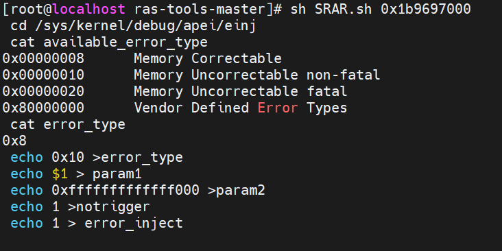
Contents of script SRAR.sh:
# SRAR.sh used for injecting uncorrectable non-fatal error, type 10
 set -v
 cd /sys/kernel/debug/apei/einj
 cat available_error_type
 cat error_type
 echo 0x10 >error_type
 echo $1 > param1
 echo 0xfffffffffffff000 >param2
 echo 1 >notrigger
 echo 1 > error_inject
Contents of script injection_error.sh:
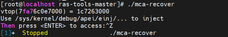
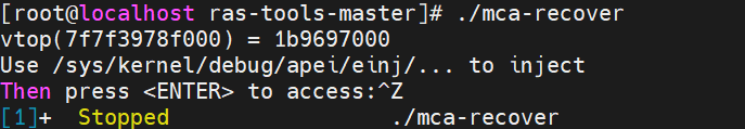
# injection_error.sh used for injecting different type of errors and can specify consumed or not. cd /sys/kernel/debug/apei/einj cat available_error_type if [ $1 == 8 ] || [ $1 == 0x8 ] then echo "Injecting Correctable Memory Error" elif [ $1 == 0x10 ] || [ $1 == 16 ] && [ $5 == 0 ] then echo "Injecting Uncorrectable Unconsumed Memory Error" elif [ $1 == 0x10 ] || [ $1 == 16 ] && [ $5 != 0 ] then echo "Injecting Uncorrectable Consumed Memory Error" echo "Set to immediate consumption when error is injected" echo 1 > notrigger elif [ $1 == 0x20 ] || [$1 == 32] then echo "Injecting uncorrectable fatal Memory Error" echo 1 > notrigger else echo "Invalid error type supplied" exit 1 fi echo $1 > error_type echo $2 > param1 echo $3 > param2 echo "Injecting $4 errors at address $2." echo "System performance will be affected while errors are being injected." for ((i=1; i <= $4; i++)) do echo "inject times: $i" echo 0x1 > error_inject sleep 0.01 done echo "Injection Complete" - An executable binary file “mca-recover” shows how to set up a SIGBUS handler for recoverable machine checks and creates virtual address and physical address mapping. Run it, capture virtual and physical page mapping, and then press “Ctrl-Z” to stop. Note that you do not press ENTER after running the script because accessing the address should occur after the page has been retired and the page flag is confirmed to be set to poison.
In this example, you can see that the virtual address 0x7fa76c0e7000 is mapped to the physical address 0x1c7263000.
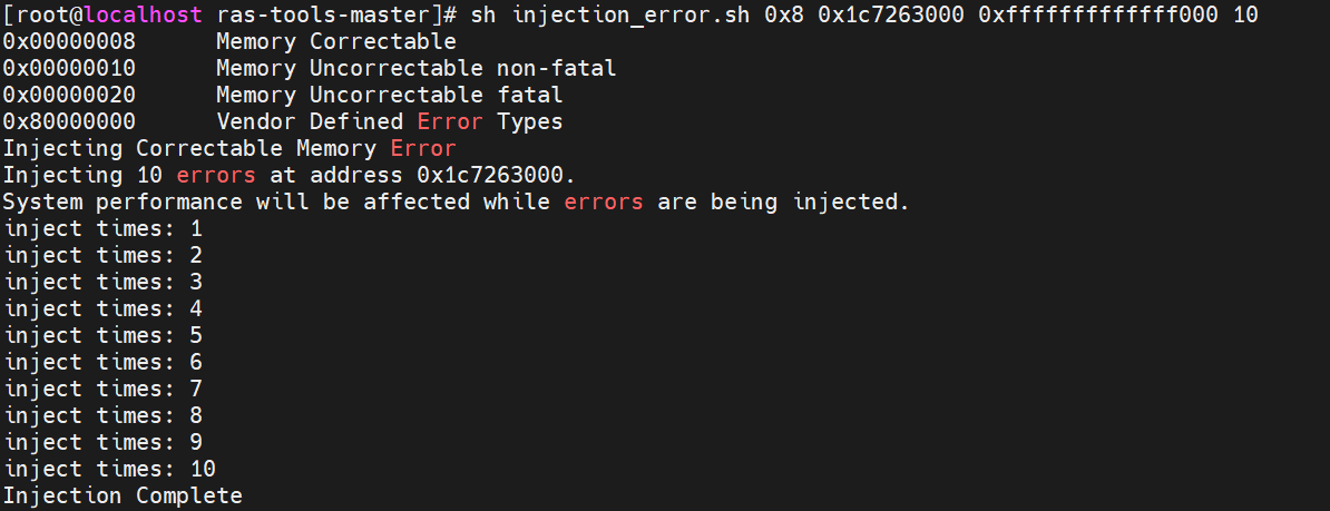
- Inject memory correctable errors (type 0x8) by executing injection_error.sh, using the following parameters:
sh injection_error.sh 0x8 <physical address from step 7> 0xfffffffffffff000 <number of injections>
The output is displayed as follows.
- Check errors.
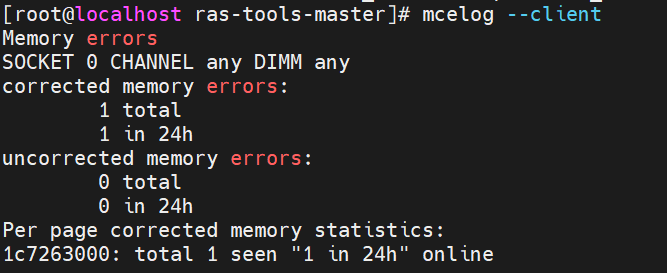
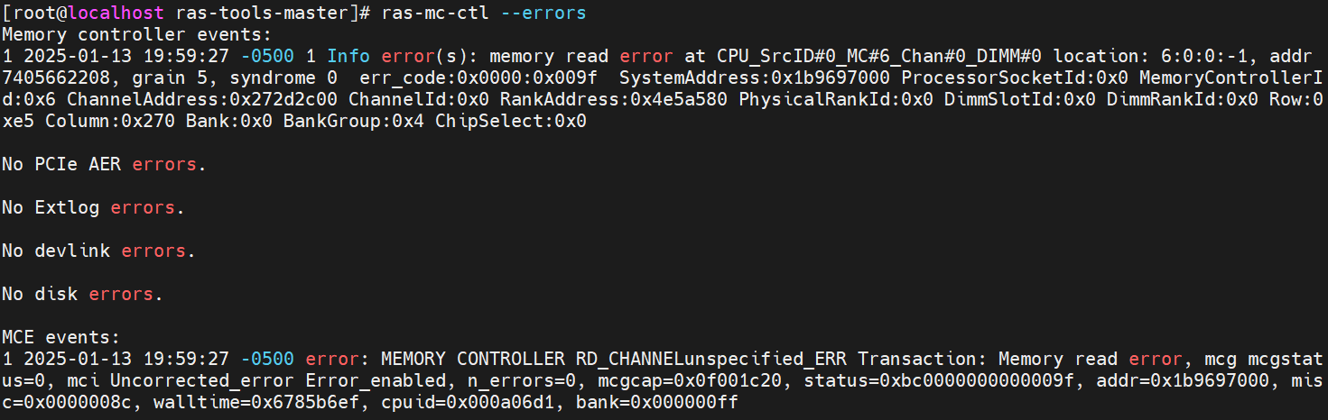
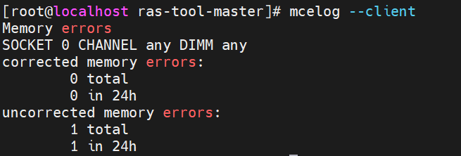
- Run “mcelog --client” and you can see a corrected memory error on the address we injected to.
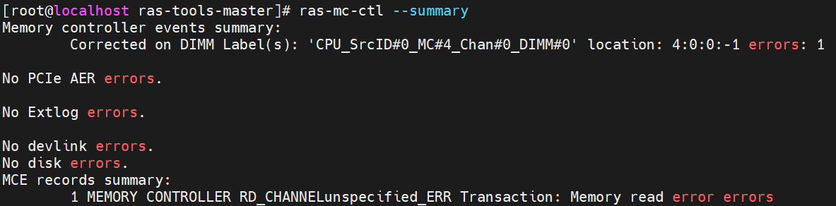
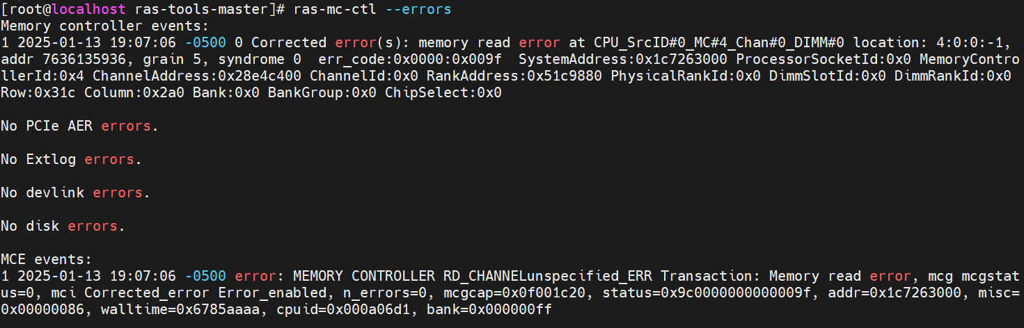
- Run “ras-mc-ctl --summary” and “ras-mc-ctl --errors” as the following screenshot, and an MCE event was recorded.
- Check the value of HardwareCorrupted. Page size 4KB was corrupted, as shown below. It means the physical page is poisoned and taken offline.
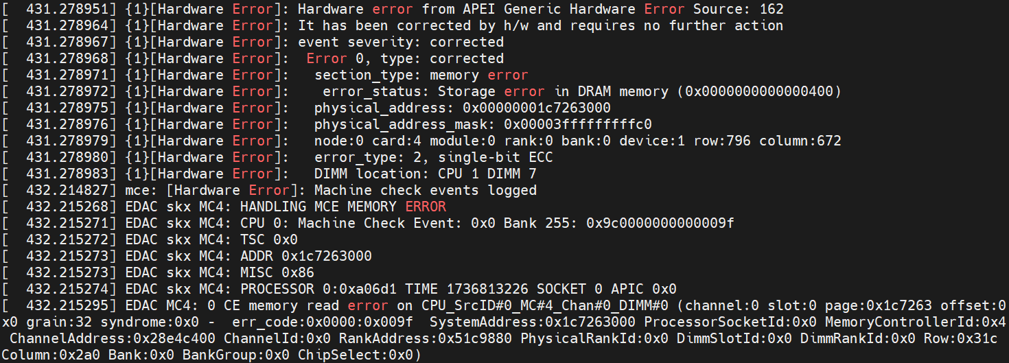
- Check dmesg (run “dmesg” in the terminal), and you can see some logs related to a memory read corrected hardware error, showing that the physical address is the one we injected to. It also includes the detailed location of the error, such as the specific CPU, IMC, Channel, DIMM, Rank, Bank, Row, and Column, as reported by the EDAC driver.
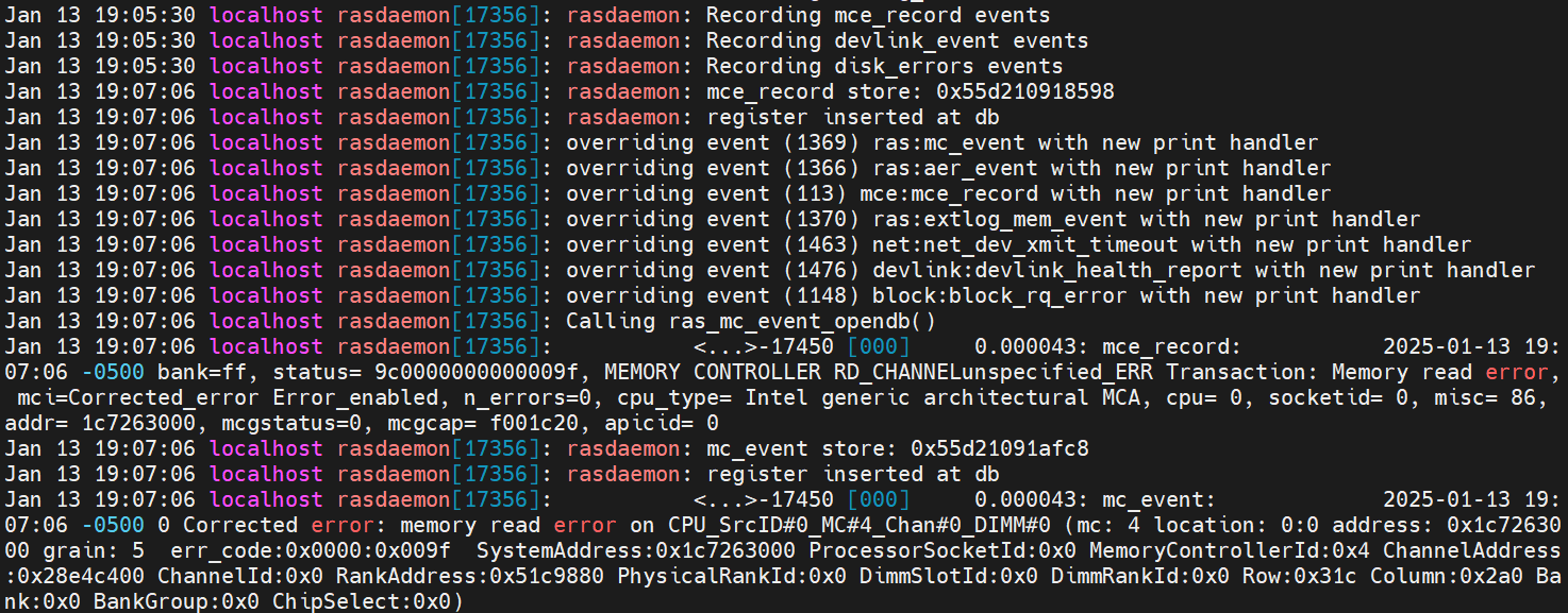
- Check /var/log/messages.
You can see logs from the mcelog service, which also shows that the memory read correctable error occurred at physical address 0x1c7263000 in our example.
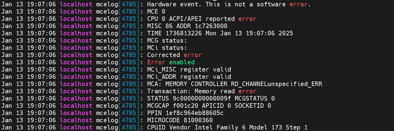
Figure 25. Mcelog server output in /var/log/messagesSome rasdaemon logs will also be outputted. MCE recorded an entry via FTrace, and an mc event entry was inserted into the database.
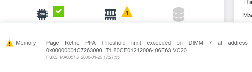
- Check the system event log from BMC; the High PFA threshold limit should not be exceeded. For achieving “T1” PFA policy, wait for more than 3 minutes and then run Step 9 again to inject to the same page, and the event log below will be reported to BMC.
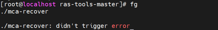
- Restart the process that was temporarily halted in Step 8 using the command “fg”. Then press “Enter”. Before the OS takes the physical page offline, it helps to allocate a new physical page and update the page table for creating a new mapping to the virtual address. In addition, the OS also copies the data from the previous page to the new one. While re-running the application to access the virtual address, the application is still alive, and the data is the same as before.


Testing Machine Check Recovery
This section describes the integration and validation of MCA Recovery. MCA Recovery is an Intel standard RAS feature that involves silicon hardware, firmware, and OS application working together to recover from uncorrectable data errors to keep the machine operational.
This section also describes the methodology recommended for validating the MCA Recovery feature. Fault injection tools and libraries, work-load generators and libraries, and data collectors and analyzers are the key components described here. The primary objective is to validate end-to-end flow from the time a hardware error is injected to the time an application recovers successfully.
The whole framework is shown in the following figure.
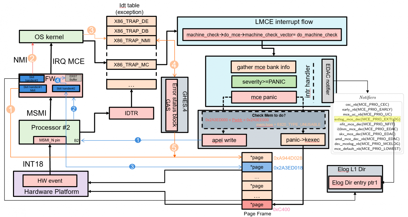
Figure 29. MCA recovery architecture
In this section:
The legacy machine checks are designed to first broadcast MCE interrupts to all processors, and then Linux OS kernel synchronizes all processors to avoid contention.
However, from Intel Purely platform and later generations, the hardware, Lenovo Firmware (which enables LMCE by default), and Linux OS kernel support local machine checks. The local MCA is designed to interrupt only the logical processor threads that attempted to consume the corrupt data, to prevent a broadcast of an MCE for recoverable error types to all threads. All actions and outcomes are the same as for the legacy broadcast machine checks.
LMCE implements the following capabilities:
- Enumeration: Software mechanism to identify HW support for LMCE.
- Control Mechanism: Ability for UEFI-FW to enable/disable LMCE. Requirement for SW to opt in to LMCE.
- Identification of LMCE: Upon MCE delivery, SW can determine if the delivered MCE was to the only one logical processor and global rendezvous participation is not required.
Machine Check Recovery classification
The figure below illustrates the error classification. Corrected errors and uncorrected errors are the two main types of errors defined in Intel MCA.
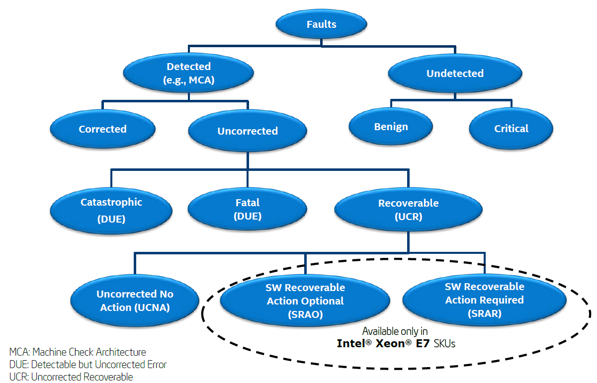
Figure 30. Fault classification (from Intel Document ID #517321)
Uncorrected errors are classified as follows:
- Catastrophic Error: This error is one type of DUE (Detected but Uncorrected Error), and it causes the system to be reset.
- Fatal Error: This error is one type of DUE, and it causes the system to be reset.
- Recoverable Error: This error is UCR (Uncorrected Recoverable Error). There are three types of recoverable errors.
- SRAR – Example: SRAR-IFU event and SRAR-DCU event
- SRAO – Example: SRAO-PS (Patrol Scrub)
- UCNA – Not signaled via an MCE (Machine Check Exception). It is reported as a corrected machine error. Example: Poison detection error
MCA in Linux OS
Machine checks triggered by multi-bit ECC (Error Correcting Code) errors in memory might be deemed recoverable by the hardware. The software layer assists recovery from uncorrectable data errors.
If the processor identifies an error that cannot be corrected by hardware, it will mark the data with a corrupted data flag, and the error event is handed off to firmware and/or the operating system. If the firmware/operating system has a redundant copy of the data, it may be able to correct the error, referring to the MCA recovery architecture figure for more details.
The Linux machine check handler will assess how the page with the memory error is being utilized, leading to the following potential outcomes:
- Page Used by the OS Kernel
If the page is in use by the OS kernel, the error is considered fatal. As a result, the system will reboot to safeguard its overall stability and integrity.
- Page Used by an Application with Unmodified Contents Known to the OS
When the page is being used by an application and the OS is aware that the page's contents remain unmodified, the error is fully recoverable. In this case, the OS will allocate a new page and reload the contents from the disk, allowing the application to continue its operation smoothly.
- Page Used by an Application without a Backup Copy
If the page is in use by an application and there is no backup copy available, the OS will send a SIGBUS signal to the process. Typically, this signal will cause the process to terminate. However, if the application is designed to be recovery aware, it can choose to catch the signal and attempt its own recovery actions to resume normal operation.
The current kernel support versions for MCA recovery on the ThinkSystem V4 platform are listed in the following table. As for the complete kernel support list, see Lenovo Support Tip HT512486.
MCA Recovery Feature Validation Recipe
This section describes the recipe to test application recovery capability on the target platform using the ACPI/EINJ method when Uncorrected Recoverable Error (UCR) error is detected by the Data Cache Unit (DCU, aka L1D).
The relevant components are listed below.
- Fault Type: Memory uncorrected error – SRAR-DCU, SRAR-IFU.
- WHEA logs, Elog, mcelog/rasdamon, or Linux FTrace.
- Validation Tools: The Linux Kernel’s DebugFS tool using ACPI/EINJ method for error injection, and Intel In-Target Probe (Intel ITP)/CScripts, CScripts is not used in the following case.
- Workload: Intel provided a simple application named einj-mem-uc.c, as mentioned in the EINJ section above, to access main memory.
Note: This recipe requires the user to log in as root (or super user).
Make sure to enable Elog before you start your test. Elog will be generated for both correctable errors and uncorrectable errors on Lenovo ThinkSystem V4 platforms with Intel Birch Stream, but if the Linux OS wants to parse Elog info correctly, the following conditions should be matched:
- Pass precise CPU and bank number to the OS.
UEFI uses WHEA to notify the OS without passing the CPU number and the bank number, so the way that WHEA cooperates with the SCI interrupt is unable to drive the OS to parse Elog. That’s why no Elog is output in kernel dmesg in our PFA test. On the other hand, since the CMCI and MCE interrupt handlers in the Linux OS can scan all CPU banks on their own, the CPU number and the bank number can be passed to the Elog handler.
- Bank data in the CPU cannot be cleared by UEFI.
For the uncore bank, for example, in the situation that IMC consumes data and then UCNA is triggered, Lenovo UEFI is designed to clear the bank data after filling Elog, so even though the uncore bank number is passed to the OS, the OS Elog handler still cannot get that info.
For the core bank, for example, in the situation that DUC consumes data and then SRAR is triggered, Lenovo UEFI is designed to keep the bank data after filling Elog and send the MCE notification to the OS, so that the OS can correctly parse the Elog data with precise CPU number and bank number passed by MCE handler.
In the test “mce_recover + SRAR.sh”, no Elog messages are output, that is because the error data is only consumed by IMC and UEFI only sends SCI notification to the OS after filling WHEA, the purpose of which is that UEFI wants to use the page retirement flag in WHEA to notify the OS to take the error page offline.
In the test “einj_mem_uc -f ‘single’”, in the first phase, the data is first consumed by IMC, which is the same as in “mce_recover + SRAR.sh”. However, “einj_mem_uc -f ‘single’” will access the physical address where the error occurred immediately, so the error data will also be consumed by DCU. UEFI will fill Elog again and send MCE notification to the OS without clearing the core bank data this time.
Note that UEFI doesn’t fill WHEA in the second phase because the page can be taken offline by the OS MCE interrupt handler.
- Disable the RAS_CEC driver.
There could arise a situation where it could be necessary to compile out or disable the RAS_CEC driver. RAS_CEC (Correctable Error Collector) is a Linux driver used for Predictive Failure Analysis. If the RAS_CEC driver is enabled, the OS will skip parsing Elog data. But disabling RAS_CEC has a side effect that correctable errors will be hidden outside of the kernel. This means there will be no dmesg or FTrace events for correctable errors.
However, thanks to Lenovo ThinkSystem UEFI, the correctable error can be logged and has more refined management based on memory DIMM from different manufacturers. To be more specific, for the situation that manufacturer A's memory DIMMs can withstand a maximum of 10 correctable errors per rank, while manufacturer B's memory DIMMs can withstand 20 correctable errors, Lenovo UEFI can still handle.
Most Linux OSes have “CONFIG_RAS_CEC=y” in their kernel config files, so we should disable RAS_CEC with a kernel command line “ras=cec_disable”.
Linux's Elog module is CONFIG_ACPI_EXTLOG. Make sure that this is compiled in the kernel that you are using. If the command “lsmod” does not return anything, it implies that Elog is not configured. The results should be output as below after performing “modprobe acpi_extlog” and “lsmod | grep acpi_extlog”.
# modprobe acpi_extlog
# lsmod | grep acpi_extlog
acpi_extlog 20480 0
Data of Elog will either be printed to dmesg or FTrace, but not both. Whether Elog data is printed to dmesg or FTrace depends on whether "rasdaemon" is active. If we want to make sure that Elog data will be sent to FTrace, manually set "rasdaemon" to be active. You can install "rasdaemon" as described in the section "Rasdaemon".
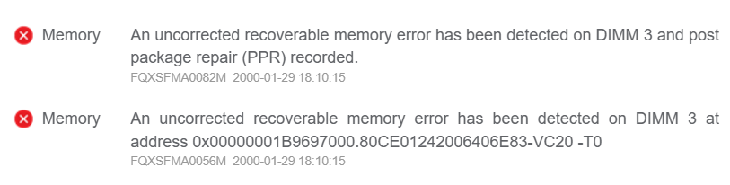
When an uncorrected recoverable memory error has been detected, a System Event Log (SEL) will be reported to BMC via the Lenovo ThinkSystem UEFI. Therefore, when checking the BMC Web GUI or SEL log, a message similar to the following should be displayed:
An uncorrected recoverable memory error has been detected on DIMM 3 at address 0x00000001B9697000.80CE01242006406E83-VC20 -T0
The template is:
FQXSFMA0056M: An uncorrected recoverable memory error has been detected on DIMM [arg1] at address [arg2].[arg3][arg4]
The meanings of those “arg” parameters in the output are shown below. For other output details, see https://pubs.lenovo.com/sr630-v4/FQXSFMA0056M.
[arg1] DIMM Silk Label, 1-based
[arg2] Address of the system where the error occurred
[arg3] DIMM identifier consists of S/N, FRU and UDI, e.g. "739E68ED-VC10 FRU 0123456"
[arg4] Indicate the error is UCNA or SRAR, "-T0" for UCNA, "-T1" for SRAR
The Lenovo ThinkSystem V4 platform handles uncorrectable memory errors differently depending on where the error is consumed - either in the uncore (IMC) or core (DCU) memory banks. This results in two distinct error handling scenarios with different system behaviors and outcomes, as described below:
Case 1: Trigger UCNA
When errors are consumed only in the IMC uncore bank, the system triggers UCNA (Uncorrectable No Action) handling. In this case, UEFI clears the uncore bank data after recording in Elog and notifies the OS via SCI/WHEA for page retirement. The affected application continues running until it accesses the faulty memory address, at which point it receives SIGBUS and terminates.
The steps are as follows:
- This recipe is quite similar to the one used to validate the PFA feature. Follow steps 1-8 in the PFA Feature Validation Recipe section. We will get the virtual and physical page mapping as below.
- Inject a memory uncorrected non-fatal error by executing “SRAR.sh” to test SRAR-DCU with the parameter we got in the last step, which is shown in the following figure.
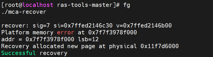
- Restart the mca-recover process that was temporarily halted in Step 1 using the command “fg”. Then press “Enter”, and “mca-recover” recovers virtual page to map to a new physical page 0x11f7d6000, like the following figure.
- Check errors.
- Run “mcelog –client” and you can see an uncorrected error shown below.
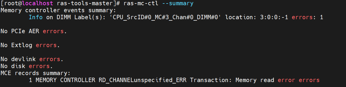
- Run “ras-mc-ctl --summary” and “ras-mc-ctl --errors”, as shown in the following screenshot, and an MCE event was recorded.
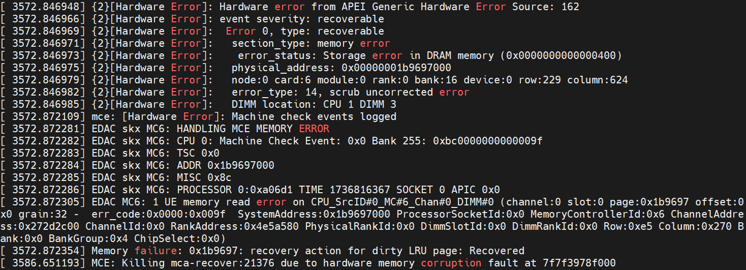
- Check dmesg, and you can see some logs related to hardware errors as below. The output indicates:
- The notification comes from APEI Generic Hardware Error Source 162, which means the interrupt from SCI.
- A scrub uncorrected memory error that is recoverable at physical address 0x1b9697000, indicating that IMC consumes the error data at this point of time.
- The EDAC driver points to the detailed location of the memory read error.
- The program mca-recover was killed after pressing the “Enter” key in Step 3. It indicates that the SIGBUS signal is triggered by the page fault execution path, not by the MCE handler. Since the physical page had already been taken offline in the SCI handler earlier, when the application attempts to access the corresponding physical page through a virtual address, a page fault occurs, leading to the recreation of a page table for the newly allocated page.
- Check /var/log/messages, and you can see logs from the mcelog server and rasdaemon as shown below. An uncorrectable memory read error is reported from “CPU 0 ACPI/APEI”.
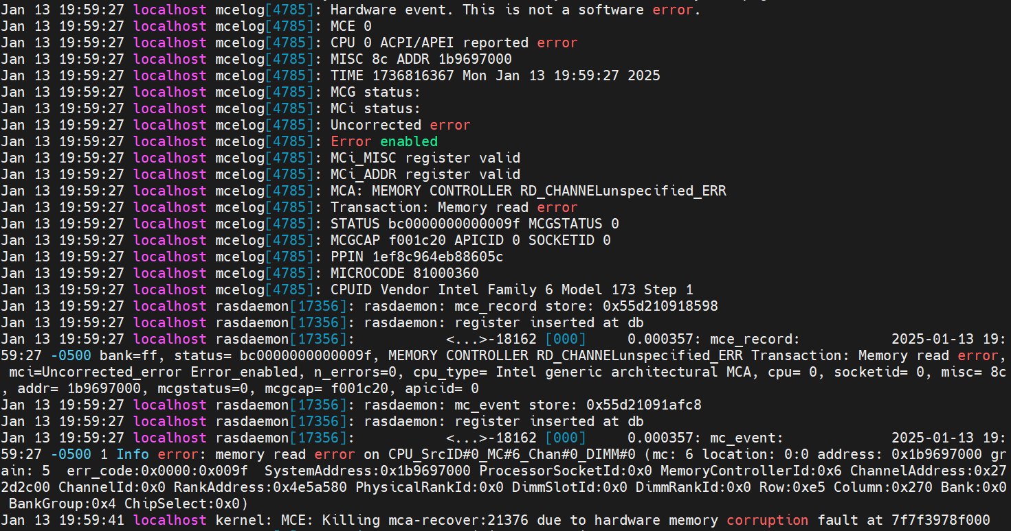
Figure 38. Mcelog server output and rasdaemon logs in /var/log/messages - Check the system event log from BMC, an uncorrected recoverable memory error has been detected and matches the uncorrectable “T0” policy. The following figure shows what it looks like. Note that UEFI also logs a PPR (Platform Error Record) and sends it to the BMC on Lenovo ThinkSystem Birch Stream Platform.

Case 2: Trigger SRAR
When errors propagate to and are consumed by core DCU banks, the system triggers SRAR (Software Recoverable Action Required) handling. Here, UEFI preserves the core bank data in Elog and sends an MCE interrupt to the OS. The offending process immediately receives SIGBUS and terminates, while the OS handles page retirement through its MCE handler.
The steps are as follows:
- This recipe is quite similar to the one used to validate the PFA feature. Follow steps 1-6 in the PFA Feature Validation Recipe section.
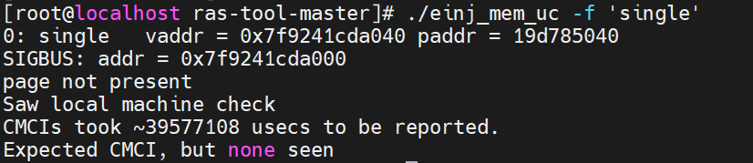
- Execute the einj_mem_uc script with the parameter “-f ‘single’”, and you can see the virtual and physical page mapping, which is shown in the following figure. Note that sometimes UCNA is triggered, and the page is taken offline very quickly, the program “einj_mem_uc” does not have a chance to access the address to load the data to DCU, so the command “einj_mem_uc -f single” will return “test failed” in this scenario.
- Check errors.
- Run “mcelog –client”. An uncorrected error is shown below.
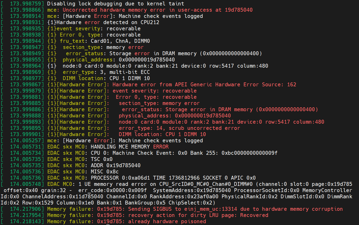
- Check dmesg (run “dmesg” in the terminal), and you can see some logs related to hardware errors below.
- The notification comes from both MCE and SCI of APEI Generic Hardware Error Source: 162.
- The Elog driver received the notification from the MCE and successfully parsed the Elog information, indicating a recoverable error on CPU 1 DIMM 10.
- The EDAC driver was notified by the SCI and pointed out the detailed location of the memory read error.
- A SIGBUS signal was sent immediately to the program “einj_mem_uc” because the error data was accessed by the application shortly after injection. As a result, the error data was consumed in the DCU, triggering an MCE. The MCE handler detected that the error occurred in user space and was recoverable, leading to the setting of a hardware memory corruption flag.
- The application “einj_mem_uc” recovered successfully.
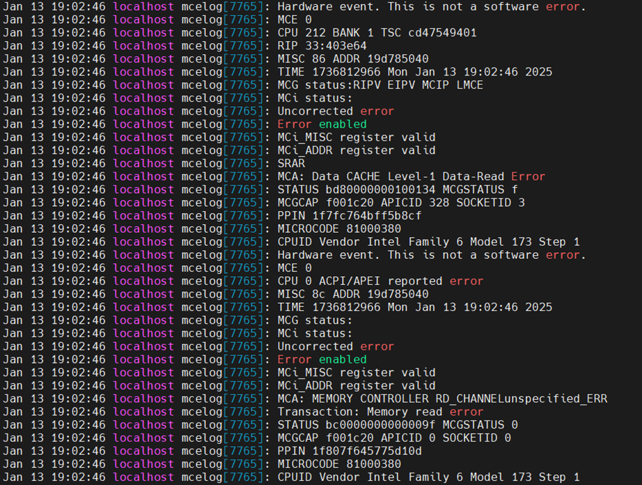
- Check /var/log/messages, and you can see logs from the mcelog service below. Apparently, the mcelog daemon was woken up twice. The first one is from the MCE interrupt that points out this is a “Data CACHE Level-1 Data Read Error”. The second one is from the SCI interrupt that points out this is a “MEMORY CONTROLLER READ_CHANNEL unspecified_ERR”.
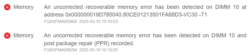
- Check the system event log from BMC. An uncorrected recoverable memory error has been detected. And it reaches the “T1” policy, which represents the occurrence of SRAR. The following figure shows what it looks like.
Testing Memory Mirroring
Memory address range mirroring is a new memory RAS feature on Intel that allows greater granularity in choosing how much memory is dedicated to redundancy. In normal channel mirroring, also known as full memory mirror, the memory is split into two identical mirrors (primary and secondary). Half of all installed memory is reserved for redundancy and not reported in the total system memory size.
Memory Address Range Mirroring offers a more refined approach to memory mirroring. It enables the firmware or the operating system (OS) to specify a particular range of memory addresses for mirroring, while keeping the remaining memory in the socket in non-mirror mode.
This type of memory mirroring implementation is designed to mirror critical memory regions without the need to mirror the entire socket's memory, thus reducing associated costs. Moreover, dynamic failover to the mirrored memory is transparent to both the OS and applications without a system reboot.
For the critical software execution part, mirror only the user-defined memory address range via BIOS or OS. For instance, users can mirror only the OS kernel space while configuring the rest of the memory in independent mode. So, it is a more cost-effective mirroring solution that involves mirroring only the critical portion of the memory instead of the entire memory space. This approach ensures system uptime even when an uncorrected fatal memory error event is detected.
In conclusion, the strengths of memory address range mirroring are:
- Provide further granularity to mirroring of memory by allowing the firmware or OS to determine a range of memory addresses to be mirrored, leaving the rest of the memory in the socket in non-mirror mode.
- Reduce the amount of memory reserved for redundancy.
- Improve high availability by avoiding uncorrectable errors in kernel memory in the Linux system by allocating all kernel memory from mirrored memory.
Topics in this section:
Memory Address Range Mirroring Support
This section outlines the firmware and OS requirements for implementing memory address range mirroring. The following subsections detail the necessary UEFI implementation, and Linux-OS handling to ensure proper configuration and operation of mirrored memory.
Requirements for OS and Firmware
Address Range Mirroring requires OS support:
- The OS needs to be aware of the mirrored region. UEFI pass those regions via EFI memory map table, as known as E820 table
- The OS should be capable of parsing the user parameter kernelcore=mirror and then configuring the amount of memory for allocations that cannot be reclaimed or migrated.
Provides Firmware-OS interface:
- UEFI Variables: A method to request the amount of mirrored memory.
- UEFI Memory map: Presents a mirrored memory range on the platform.
UEFI
On the first boot of a system that supports memory address range mirroring, the BIOS must create the “MemoryCurrent” variable and initialize it to values supplied by BIOS setup options. If there are none, then use: [1 for false, 0 indicates EFI_SUCCESS].
Note that once “MemoryCurrent” is corrupted or does not exist in a subsequent boot, the BIOS must create it. On each subsequent boot, the BIOS should first check if “MemoryRequest” has been set by the OS to request a change in mirror configuration. If it is, then the BIOS should try to set up mirroring using the new parameters:
- If successful, copy parameters from “MemoryCurrent” and set MemoryCurrent.MirrorStatus=EFI_SUCCESS.
- If not successful, set MemoryRequest.MirrorStatus with an error code and fall through to the normal path to set mirroring using the old parameters.
If “MemoryRequest” was not set, then the BIOS should set up mirroring from parameters in “MemoryCurrent” and set MemoryCurrent.MirrorStatus to indicate the success/failure status.
Features supported by UEFI are:
- Enable and disable mirroring of memory below 4 GB for a subsequent boot
- Specify the amount (up to 50%) of memory to be mirrored for a subsequent boot
- Indicate whether memory below 4 GB is mirrored for the current boot
- Indicate the amount of memory mirrored for the current boot: The status of requested memory redundancy during the last boot and status of request – SUCCESS, FAILURE, PARTIAL.
Linux OS
During early boot, the OS uses the attribute bits returned by GetMemoryMap() to locate which ranges of memory are mirrored. GetMemoryMap() returns to the OS all the address ranges presented by the platform. Note that UEFI Call GetMemoryMap() is part of the UEFI BOOT services and hence cannot be invoked after ExitBootServices().
During hot plug memory operations, the OS uses the _ATT attribute field to discover changes to the memory mirror configuration.
Later, it examines MemoryCurrent and MemoryRequest to check for errors in setting up mirror ranges.
To change the mirror configuration, the OS sets MemoryRequest to [1,desired-below-4GB,EFT_WARN_STALE_DATA] and then reboots to allow the BIOS to apply the new settings.
Read/Write Strategy
Without Mirroring, in 2-way interleave, addresses are interleaved between two channels. Memory reads and memory writes will happen between two channels. In 4-way interleave, addresses are interleaved between four channels. Memory reads and memory writes will happen across all four channels.
Read/Write Strategy of Address Range Memory Mirror
Address Range Memory Mirroring improved the read/write efficiency using effective channel interleave. As shown in the following figure, N+n represents the data in the memory. Memory reads are interleaved between the four channels for the mirrored region and interleaved between two channels for non-mirrored regions. Memory Writes are interleaved between the two channels for both mirrored region and non-mirrored regions.
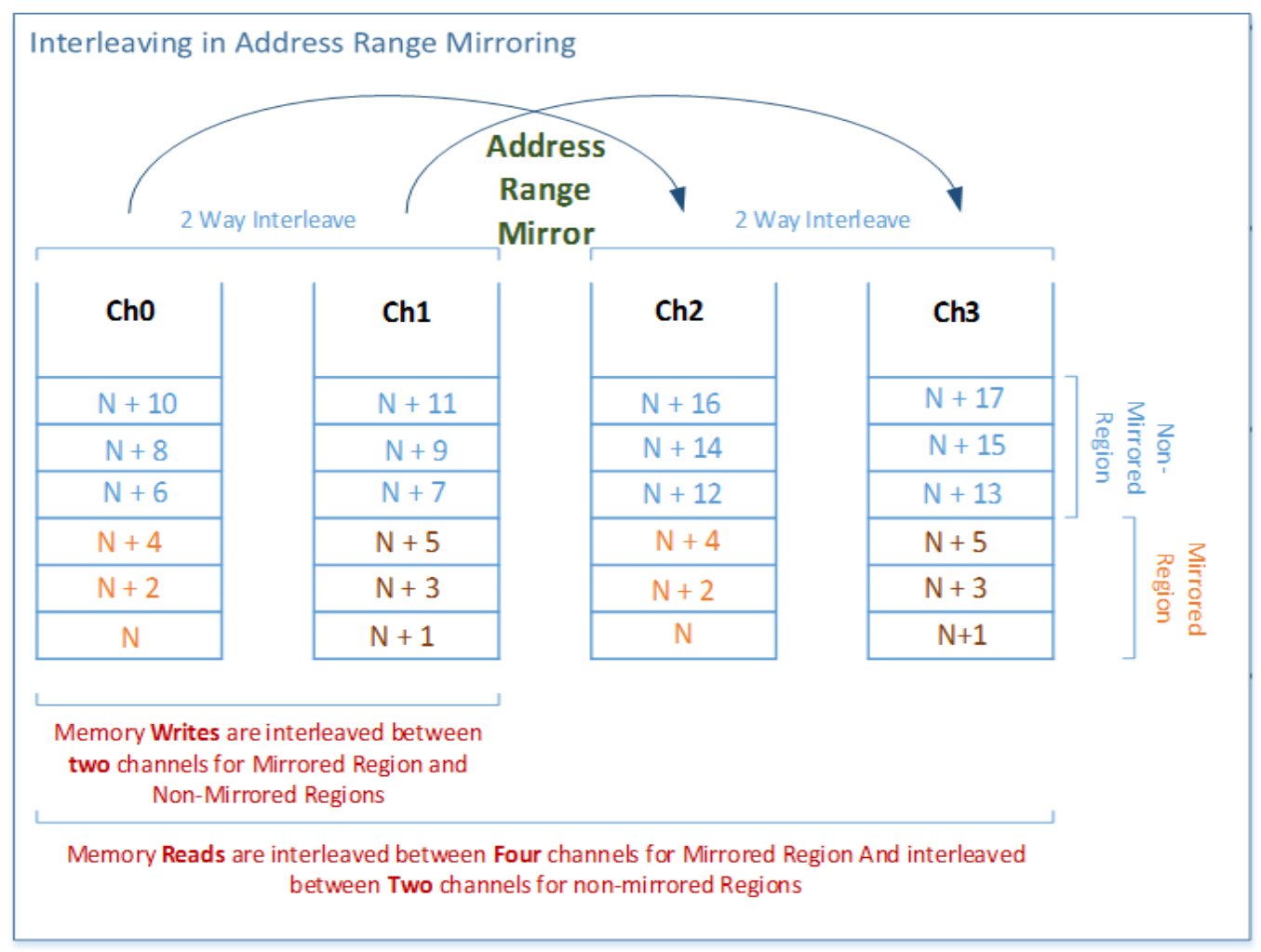
Figure 45. Interleave in Address Range Mirroring (from Intel Document ID #551534)
Read/Write Strategy of Full Memory Mirror
With full Mirroring, addresses are interleaved between two channels. Memory writes will happen across two channels. Memory reads will happen across all four channels as shown in the figure below.

Figure 46. Interleave in Full Mirroring (from Intel Document ID #551534)
Memory Mirroring Configuration
Memory mirroring is a method of keeping a duplicate (secondary or mirrored) copy of the contents of memory as a redundant backup for use if the primary memory fails. The feature is implemented in the hardware/software, and with the option for the end user to enable the system operation in mirror mode. Total available memory is reduced in mirror mode as all the memory at the slave is now used as duplicate memory. This affects the overall system performance, but it is a known compromise for the end user who is more concerned about data availability.
Mirroring may be configured for:
- A portion of the address space (address range mirroring/partial mirroring). Mirroring is handled by the M2Mem (Mesh 2 Memory) logic in the IMC (Integrated Memory Controller). The following test verification is described in detail.
- Uncorrectable Error in a Mirrored Region.
The objective of this test is to inject an uncorrectable error into a specified address located within the mirrored address region of memory, read the target cache-line, then verify that the system stays operational and B2CMI's MCA bank logs a correct error and MIRRORCORR=1 is set in IA32_MCi_MISC register.
- Uncorrectable Error in a Mirrored Region.
- Full memory mirroring. Half of all installed memory is reserved for redundancy and not reported in the total system memory size. Mirroring is handled by the B2CMI (Bridge to Converged Memory Interface) logic in the IMC, which includes three types of test verification listed below.
- Correctable Error on Primary Channel
This test aims to verify the correctable ECC error flow on the primary channel for a mirrored region. Particularly, to point out how the flow is not any different compared to a non-mirrored region.
- UCE on Primary Channel
This test aims to verify the uncorrectable ECC error flow on the primary channel for a mirrored region. The expected outcome is that B2CMI requests the same data from the secondary channel to correct the error and scrubs the primary channel with good data. The section validation recipe below will use this case as an example for illustration.
- Persistent UCE on Primary Channel
This test aims to verify the mirror failover by injecting a persistent UCE error on the primary channel. The expected outcome is that B2CMI requests the same data from the secondary channel to correct the error and scrubs the primary channel with good data, but the scrubbing fails, and the primary channel fails over to the secondary channel.
- Correctable Error on Primary Channel
Memory Mirror in Linux OS
In Linux, there are two methods for managing physical memory: "memblock" and "Zone Allocator". The "memblock" mechanism manages memory blocks during the early bootstrapping phase. Once the system initialization is completed, it is phased out, and the "Zone Allocator" takes over memory management.
Each memory block consists of two arrays, , as shown in the figure below:
- "memory[]" array, which represents the available memory in the system
- "reserved[]" array, which stores the allocated memory ranges
The limitation of the "memblock" mechanism is that it can only allocate memory regions from the "memory[]" part. Support for memory mirroring in the "memblock" has been integrated into the Linux kernel version 4.3.
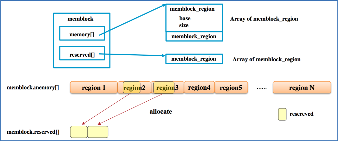
The “Zone Allocator” is the standard kernel memory allocator. It is responsible for managing memory regions known as “zones”.
As shown in the figure below, there are three types of zones:
- ZONE_DMA
- ZONE_DMA32
- ZONE_NORMAL
The ZONE_DMA and ZONE_DMA32 are dedicated to Direct Memory Access (DMA) operations. On the other hand, the ZONE_NORMAL represents memory that is directly mapped and can be utilized by both the kernel and user space processes. In modern Linux, the additional memory zone ZONE_MOVABLE helps deal with memory fragmentation by allowing page migrations. The ZONE_MOVABLE zone contains pages that can be moved around in memory. When a large contiguous memory block is needed, pages from the ZONE_MOVABLE zone can be migrated to create a contiguous space. This helps reduce the impact of fragmentation and improve the overall efficiency of memory allocation.
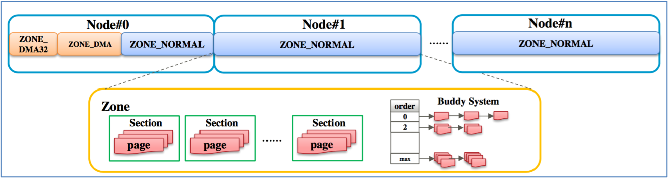
The “Zone Allocator” is an appropriate approach for implementing Address Range Memory Mirroring in a Linux system. The upstream Linux kernel version 4.6 or later already supports Address Range Memory Mirroring. The implementation of this feature relies on the “Zone Allocator”, as depicted in the figure above.
To test the new memory RAS (Reliability, Availability, and Serviceability) feature, you must specify “kernelcore=mirror” in the boot options. As shown in figure below, non-mirrored memory regions will be assigned to the ZONE_MOVABLE, and the kernel will allocate memory solely from the mirrored regions.
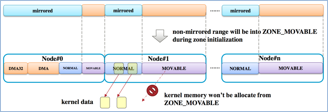
Full Memory Mirror Feature Validation Recipe
This section describes the methodology recommended for validating the Persistent UCE on Primary Channel of Full Memory Mirroring Feature to reach mirror failover. The address range memory mirror needs to use the Intel ITP tool to figure out the corresponding address in the mirror region. However, unlike the address range mirror, Full Memory Mirror ensures that the obtained address is within the mirror region.
Error injection tools and libraries, data collectors and analyzers are the key components described here. The primary objective is to validate end-to-end flow from the time a hardware error is injected to the time the error recovers successfully, regarding transaction flows in mirror processing.
For this recipe, some of the steps are based on steps in the PFA Feature Validation Recipe section, with additional steps need to be taken on this basis.
The steps are as follows:
- Set up RAS in UEFI. Follow the steps in the Set up RAS in UEFI section. Based on the steps, we also need to use UEFI FW setup options to manually configure address ranges, which is to set “Mirror Mode” to “FULL” in UEFI settings.
- From the UEFI Setup main page, select System Settings > Memory > ADDDC Sparing to disable it as below, so that we can configure the mirror mode.
- From the UEFI Setup menu, select System Settings > Memory > Mirror Configuration > Full Mirror to enable it as shown below.
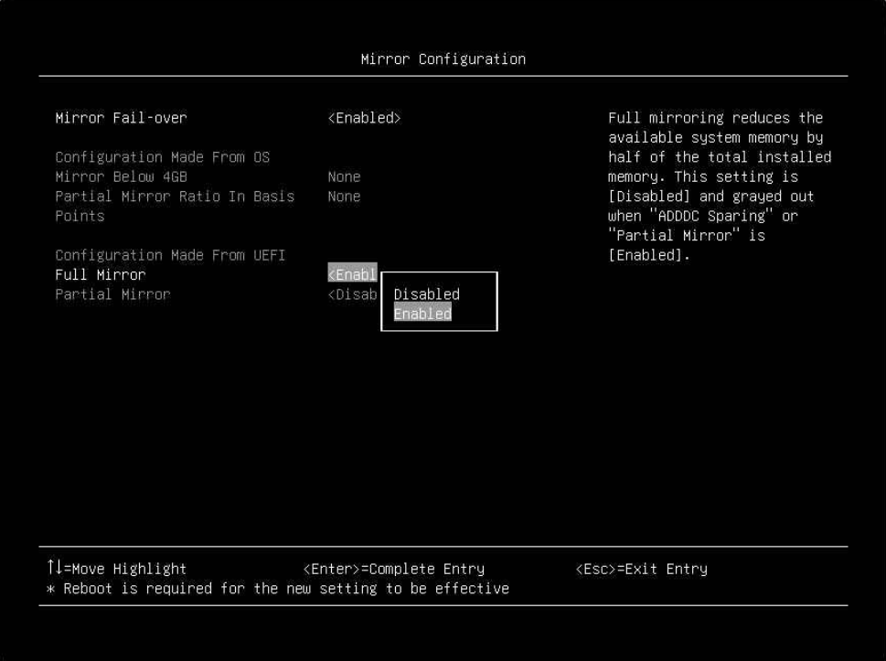
Figure 51. The Full Mirror mode setting in the UEFI setup menu - After setting the full memory mirror, check that the memory configuration aligns with what is expected. In the full memory mirror, active memory capacity is equal to half the installed capacity. All channels are operating in mirror mode, and the mirror size is equal to the active memory size. Before setting the full memory mirror, the UEFI post screenshot is shown in the following figure, which shows independent mode enabled with usable capacity 512 GB.
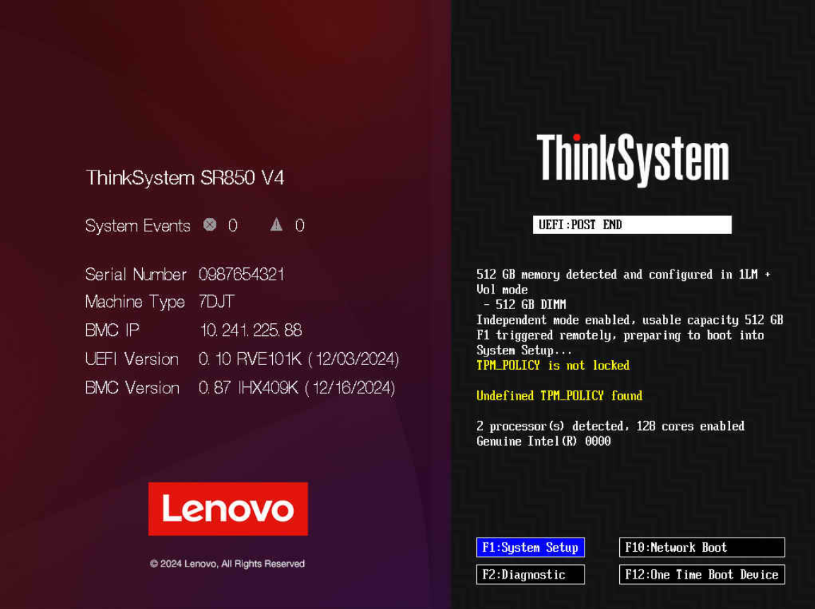
Figure 52. The UEFI post screenshot in Independent modeAnd after setting, as the UEFI post screenshot shown below, the reported mirror size values were observed to be accurate and aligned with expectations.
- Follow the Step 2 of PFA Feature Validation Recipe.
- Follow the Step 3 of PFA Feature Validation Recipe. Besides, append “kernelcore=mirror” to the kernel parameter, and you will see that the cmdline is like the figure below after system startup.
- Check efibootmgr. The OS utility efibootmgr can set a mirror as well. The efibootmgr command can determine if mirroring is supported on a platform, and set UEFI boot variables to communicate to the UEFI-FW how much memory (percentage of total system memory) should be mirrored. However, currently it can only set a partial mirror. If we want a full mirror, we should make sure the UEFI setting is valid, which needs efibootmgr to be the default setting (so that it won’t affect the UEFI setting). Thus, make sure that MirrorMemoryBelow4GB is false and MirroredPercentageAbove4G is 0 as the following figure. If not, run the following command then reboot.
efibootmgr -m f -M 0
- Check dmesg. Filter out rows with “mirror”, and you will see “efi: Memory: xxM/yyM mirrored memory.” In which, xx and yy should be very close, which shows that the full mirror is set.
- Check that the available memory size is changed via the command free -mh. When memory mirror is enabled, only half of the memory is left, which is shown in the following figure.

Figure 57. Check the available memory size with memory mirror enabledFor ease of reference, the original memory status is shown below.

Figure 58. Check the available memory size with memory mirror disabled - Follow steps 4-8 of PFA Feature Validation Recipe, and we will get the virtual and physical page mapping as shown below.
- Inject an uncorrectable fatal memory error (error type 0x20) by executing “injection_error.sh”, using the following parameters. In non-mirror mode, also called independent mode, the 0x20 fatal error will cause the system to pull down the CAT_ERR_N pin to reset the whole system.
Execute the following command:
sh injection_error.sh 0x20 <physical address from step 6> 0xfffffffffffff000 <number of injections> - Restart the process that was temporarily halted in Step 7 using the command fg. Then press Enter, and it will show didn’t trigger error as below. Since all memory writes in these ranges are performed on both mirror copies, if an uncorrectable error is detected on one side of the mirror, the hardware will read the other side to provide the correct data. The CPU, in cooperation with the IMC, copies the non-corrupted mirror data to the original page, and this process is transparent to the UEFI and OS.
- Run the following commands and check there are no errors in the output. Note that OS remains keeping alive during the whole validation.
# mcelog --client # cat /var/log/messages # ras-mc-ctl --summary # ras-mc-ctl --errors - Select a physics address (for example 0x54321) that belongs to kernel space, and then inject an error as in Step 8, the OS will still be kept alive.
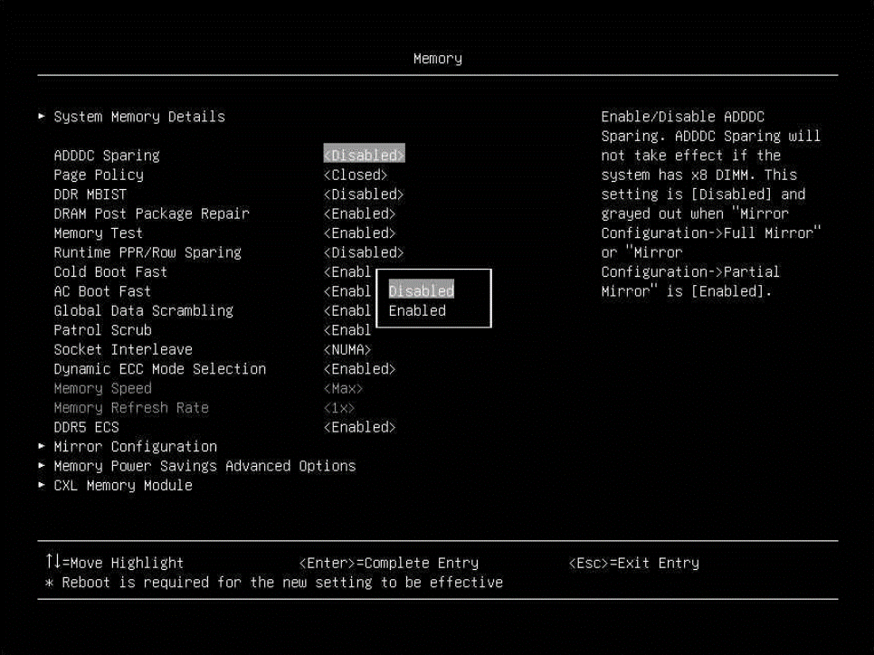
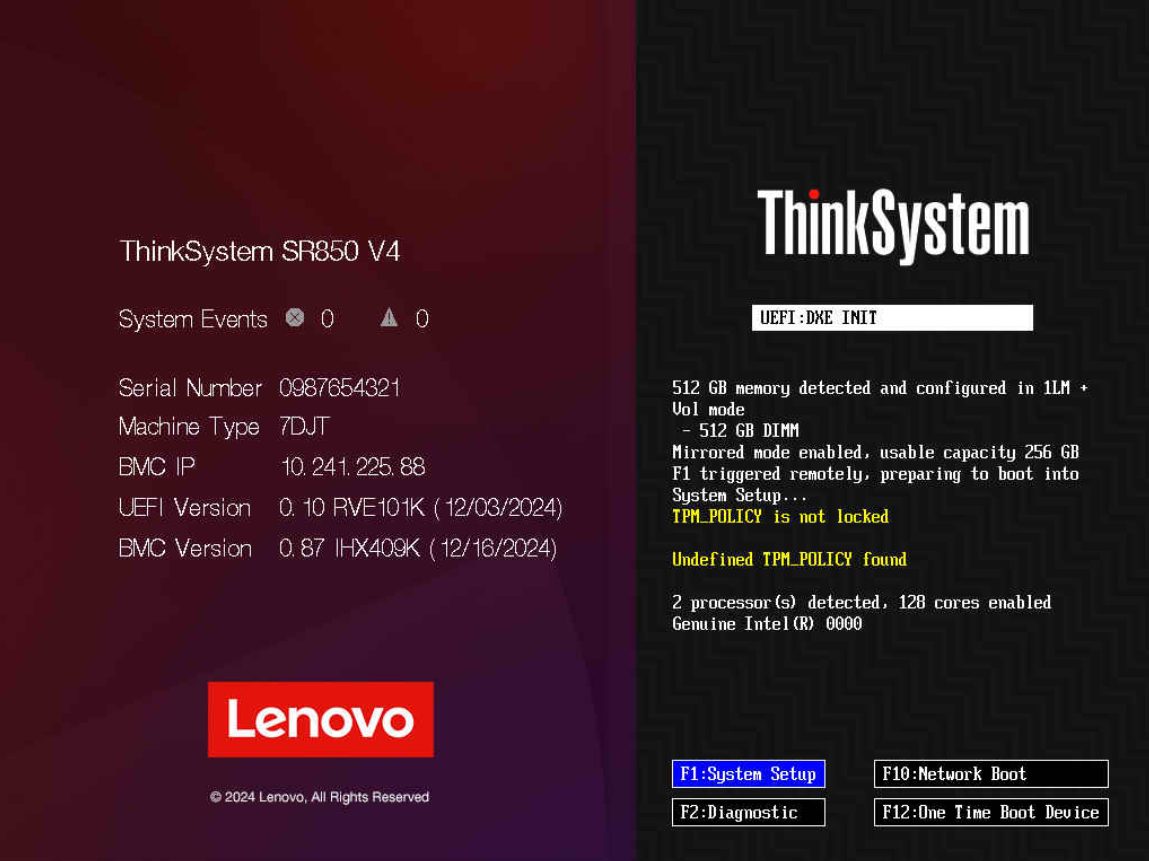

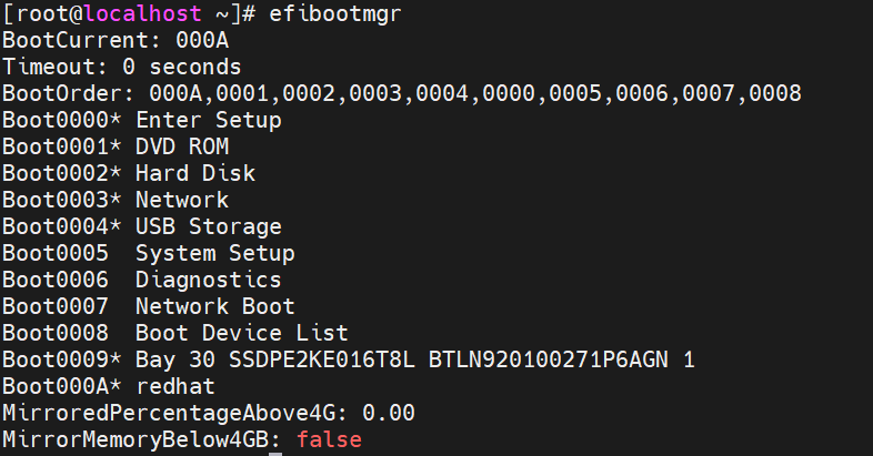
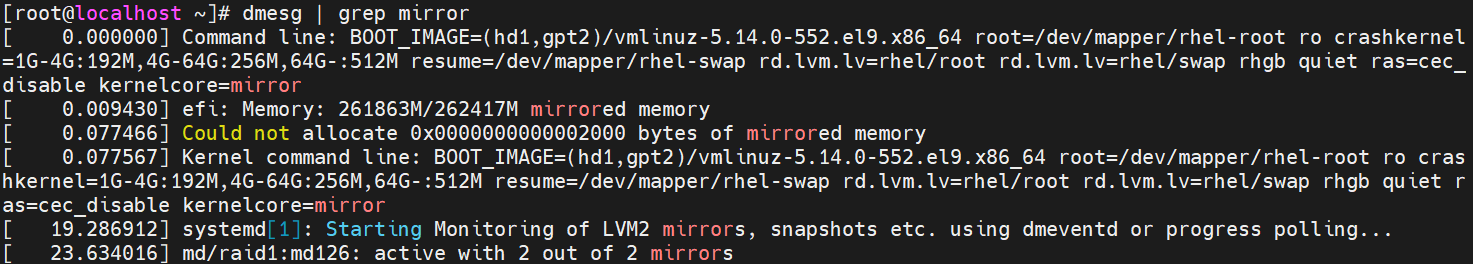
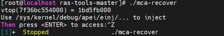
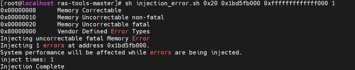
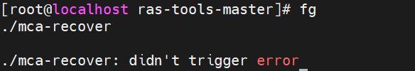
References
For more information, see these references:
- APEI Error INJection - kernel.org
https://www.kernel.org/doc/html/latest/firmware-guide/acpi/apei/einj.html - Introduction to Memory RAS (Reliability, Availability, and Serviceability) Features on ThinkSystem Servers
https://download.lenovo.com/servers_pdf/thinksystem_memory_ras_intro.pdf - Intel Document ID #575370
https://www.intel.com/content/www/us/en/secure/content-details/575370/reliability-availability-serviceability-ras-101.html?wapkw=575370 - Intel Document ID#563361: Purley Platform RAS Technology Integration and Validation Guide (IVG)
https://edc.intel.com/content/www/us/en/secure/design/confidential/products-and-solutions/processors-and-chipsets/purley/platform-ras-technology-integration-and-validation-guide-ivg/ - Intel Document ID#614168: RAS Technology Integration and Validation Guide Whitley Platform Addendum
https://www.intel.com/content/www/us/en/secure/content-details/614168/ras-technology-integration-and-validation-guide-whitley-platform-addendum.html - Intel Document ID #517321:
https://www.intel.com/content/www/us/en/secure/content-details/517321/grantley-grantley-refresh-and-brickland-refresh-platform-ras-overview.html?wapkw=517321 - Intel Document ID #551534:
https://www.intel.com/content/www/us/en/secure/content-details/551534/brickland-platform-ras-integration-and-validation-guide-address-range-mirroring.html?wapkw=Brickland%20Platform%20RAS - FQXSFMA0057G : Page Retire PFA Threshold limit exceeded on DIMM [arg1] at address [arg2].[arg3][arg4]
https://pubs.lenovo.com/sr655-v3/FQXSFMA0057G - Intel Document ID # 793802: Birch Stream Platform RAS Technology Integration and Validation Guide (FISH)
https://edc.intel.com/content/www/us/en/secure/design/confidential/products-and-solutions/processors-and-chipsets/birch-stream/bhs-ras-technology-integration-and-validation-guide-with-fish/
Authors
Xiaochun Li is a Linux engineer at the Lenovo Infrastructure Solution Group in Beijing, China. He specializes in the development of Linux kernel storage and memory management, as well as virtualization. Before joining Lenovo, he worked in INSPUR as an OS engineer for several years. With ten years of industry experience, he now focuses on Linux kernel RAS, storage, security, and virtualization.
Ziyan Fu is a Linux engineer at the Lenovo Infrastructure Solution Group in Beijing, China.
Thanks to the following people for their contributions to this project:
- Lijian, Lenovo Test Engineer for Linux Enablement
- Adrian Huang, Lenovo OS engineer
- Gary Cudak, Lenovo OS Architect
- David Watts, Lenovo Press
Trademarks
Lenovo and the Lenovo logo are trademarks or registered trademarks of Lenovo in the United States, other countries, or both. A current list of Lenovo trademarks is available on the Web at https://www.lenovo.com/us/en/legal/copytrade/.
The following terms are trademarks of Lenovo in the United States, other countries, or both:
Lenovo®
ThinkSystem®
XClarity®
The following terms are trademarks of other companies:
AMD is a trademark of Advanced Micro Devices, Inc.
Intel®, the Intel logo, Intel Optane®, and Xeon® are trademarks of Intel Corporation or its subsidiaries.
Linux® is the trademark of Linus Torvalds in the U.S. and other countries.
Windows® is a trademark of Microsoft Corporation in the United States, other countries, or both.
Other company, product, or service names may be trademarks or service marks of others.
Configure and Buy
Please select a locale
Full Change History
Course Detail
Employees Only Content
The content in this document with a is only visible to employees who are logged in. Logon using your Lenovo ITcode and password via Lenovo single-signon (SSO).
The author of the document has determined that this content is classified as Lenovo Internal and should not be normally be made available to people who are not employees or contractors. This includes partners, customers, and competitors. The reasons may vary and you should reach out to the authors of the document for clarification, if needed. Be cautious about sharing this content with others as it may contain sensitive information.
Any visitor to the Lenovo Press web site who is not logged on will not be able to see this employee-only content. This content is excluded from search engine indexes and will not appear in any search results.
For all users, including logged-in employees, this employee-only content does not appear in the PDF version of this document.
This functionality is cookie based. The web site will normally remember your login state between browser sessions, however, if you clear cookies at the end of a session or work in an Incognito/Private browser window, then you will need to log in each time.
If you have any questions about this feature of the Lenovo Press web, please email David Watts at dwatts@lenovo.com.


