

Top
Abstract
The 0U and 1U Switched and Monitored Power Distribution Units (PDUs) are the ideal solutions when you need flexible, reliable, easy-to-deploy power distribution with branch circuit protection to minimize downtime. These rack-dense units distribute power to up to 24 outlets in a 0U configuration and 12 outlets in a 1U configuration. The 0U and 1U PDUs can be used separately or in combination with other Lenovo PDUs to provide from a few outlets up to a full rack, scaling as required or as business needs change to support even greater power densities.
Withdrawn from marketing: The PDUs listed in this product guide are withdrawn from marketing.
Introduction
The 0U and 1U Switched and Monitored Power Distribution Units (PDUs) are the ideal solutions when you need flexible, reliable, easy-to-deploy power distribution with branch circuit protection to minimize downtime. These rack-dense units distribute power to up to 24 outlets in a 0U configuration and 12 outlets in a 1U configuration. The 0U and 1U PDUs can be used separately or in combination with other Lenovo PDUs to provide from a few outlets up to a full rack, scaling as required or as business needs change to support even greater power densities.
Figure 1 shows the 0U 24 C13 Switched and Monitored 30A PDU (left) and 0U 12 C19/12 C13 Switched and Monitored 50A 3 Phase PDU (right) indicating where one is installed in an 42U rack.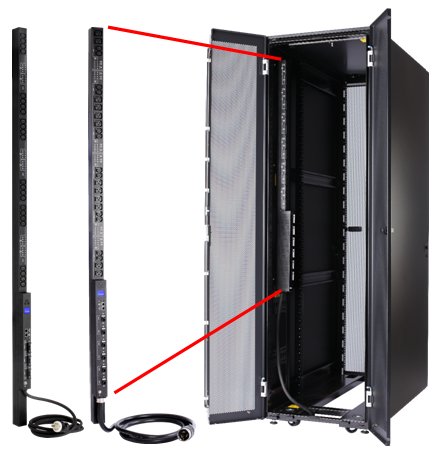
Figure 1. 0U Switched and Monitored Power Distribution Units
Did you know?
Button-mount designs on 0U PDUs help simplify deployment by providing tool-less rear mounting in certain Lenovo rack cabinets, reducing installation time.
Introduction to PDUs
A power distribution unit (PDU) is a highly reliable, multiple outlet power strip designed to consolidate line cords within the rack and distribute conditioned power from an uninterruptible power supply (UPS) or utility power to servers and other IT equipment. The PDU efficiently distributes power within the rack and provides fault-tolerant power redundancy for high availability requirements.
There are three types of PDUs available from Lenovo: basic, monitored, and switched and monitored. The PDUs covered in this document are of the switched and monitored type.
- Basic: The simplest and most cost-effective power distribution. Available with various outlet configurations and line cord options to support different systems and load requirements.
- Monitored (also known as PDU+): provides the same benefits as a Basic PDU, but adds additional advanced PDU power monitoring down to the load group. This enables businesses to have a cross-platform rack-level power and thermal view for trending analysis to improve power management.
- Switched and monitored: These are advanced power management solutions, providing power monitoring at the outlet level, with increased accuracy at low amperages, for more precise views of power consumption down to the individual server level instead of at the consolidated load group. These PDUs also offer individual outlet switching (on/off), which allows for remote power sequencing and helps prevent unintended PDU overloading. Management can be performed through web-based interface or by tools such as IBM Systems Director Active Energy Manager™.
Part number information
Table 1 lists the available 0U and 1U Switched and Monitored PDUs.
0U vertical rack strip PDUs share a common space-efficient, power-dense design across the line. Available models include 24 IEC-320-C13 single-phase and 12 IEC-320-C19/C13 3-phase receptacles with single-phase 30A and 32A offerings, and three-phase 30A, 32A, and 50A offerings (country-dependent).
Withdrawn from marketing: The PDUs listed in this product guide are withdrawn from marketing.
Table 1. Ordering part numbers and feature codes
| Description | Part number | Feature code |
| 0U 24 C13 Switched and Monitored 30A PDU (AG, AP) | 46M4116 | 5929 |
| 0U 24 C13 Switched and Monitored 32A PDU (EMEA, AP) | 46M4119 | 5930 |
| 0U 12 C19/12 C13 Switched and Monitored 50A 3 Phase PDU (AG, AP) | 46M4134 | 5931 |
| 0U 12 C19/12 C13 Switched and Monitored 32A 3 Phase PDU (EMEA, AP) | 46M4137 | 5932 |
| 1U 9 C19/3 C13 Switched and Monitored 30A 3 Phase PDU (AG, AP) | 46M4167 | 5928 |
| UPS Environmental Monitoring Probe | 46M4113 | 6146 |
The part numbers for the 0U Switched and Monitored Power Distribution Units are included with the following items:
- One Power Distribution Unit with an attached power cord
- Mounting brackets for the following racks:
- Two brackets for an S2 42U Standard Rack cabinet (Types 9307, 9956)
- Two brackets for an Enterprise Rack cabinet (Types 1410, 9308)
- One DB9-to-RJ-45 cable
- Warranty and Support Information Manual
- Rack Installation Instructions
The part number for the 1U 9 C19/3 C13 Switched and Monitored 30A 3 Phase PDU is included with the following items:
- One Power Distribution Unit with an attached power cord
- Two vertical-mounting brackets (for vertical mounting in side compartments of all racks)
- Two short mounting brackets (for horizontal mounting in all rack cabinets; for vertical mounting only in Lenovo Enterprise rack cabinets)
- Two adjustable mounting rails and six screws (for horizontal mounting in all rack cabinets)
- One DB9-to-RJ-45 cable
- Warranty and Support Information Manual
- Rack Installation Instructions
- CD containing user's guide
Figure 2 shows the 1U 9 C19/3 C13 Switched and Monitored 30A 3 Phase PDU. The rear of the 1U PDU has three C13 outlets.
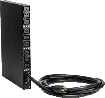
Figure 2. 1U 9 C19/3 C13 Switched and Monitored 30A 3 Phase PDU
The Environmental Monitoring Probe part number 46M4113 includes the following items:
- One Environmental Monitoring Probe
- Screws
- Hook-and-loop fasteners
- Tie wrap
- Ethernet cable
- Warranty and Important Notices Flyer
- Environmental Notices CD
The Environmental Monitoring Probe (EMP) is shown in Figure 3.
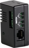
Figure 3. Environmental Monitoring Probe (EMP)
Features and specifications
The 0U and 1U Switched and Monitored PDUs have the following common features:
- Ability to access the versatile sensors in the Environmental Monitoring Probe through the environmental monitoring probe inputs (this feature requires an optional Environmental Monitoring Probe, which must be purchased separately)
- Address-specific IP security masks to prevent unauthorized access
- Comprehensive power management and flexible configuration through a web browser, NMS, Telnet, SNMP, or HyperTerminal (console)
- Configurable user-security control
- Daily history report through email
- Detailed data-logging for statistical analysis and diagnostics
- Easy-to-use interface to display input and output status
- Event notification through SNMP trap or email alerts
- Monitoring of the PDU locally or remotely through a console or network
- Remote monitoring of connected devices and sensors
- Upgrade utility for easy firmware updates
- Support for Active Energy Manager
Table 2 compares the power specifications of the 0U and 1U Switched and Monitored PDUs.
| Feature | 0U 24 C13 30A PDU | 0U 24 C13 32A PDU | 0U 12 C19/12 C13 32A 3-phase PDU |
0U 12 C19/12 C13 50A 3-phase PDU | 1U 9 C19/3 C13 30A 3-phase PDU |
|---|---|---|---|---|---|
| Part number | 46M4116 | 46M4119 | 46M4137 | 46M4134 | 46M4167 |
| Input power | |||||
| Number of phases | Single phase input | Three phase input | |||
| Line cord | Fixed line cord, 3 m length (9-ft, 10-in) | ||||
| Line cord connector | NEMA L6-30P | IEC-309 P+N+Gnd | IEC-309 3P+N+Gnd | CS8365L 3P+Gnd | NEMA L21-30P |
| Plug design |  |
 |
 |
||
| Input voltage | 200-208 V | 220-240 V | 380-415 V | 200-208 V | 200-208 V |
| Input current rating | 30 A | 32 A | 32 A | 50 A | 30 A |
| Maximum power rating | 6,240 VA | 7,680 VA | 22,920 VA | 18,013 VA | 10,808 VA |
| Output power | |||||
| Number of C13 outlets | 24 | 24 | 12 | 12 | 3 |
| Number of C19 outlets | 0 | 0 | 12 | 12 | 9 |
| Output voltage rating | 200-208 V | 220-240 V | 220-240 V | 200-208 V | 200-208 V |
| Output current rating | 30 (derated 24 A) | 32 A | 32 A per phase 96 A total |
23.09 A per phase (derated) 69.27 A total (derated) |
13.85 A per phase (derated) 41.55 A total (derated) |
| Single power outlet current rating | C13: 10 amps (VDE) / 15 amps (UL/CSA) | C13: 10 amps (VDE) / 15 amps (UL/CSA) C19: 16 amps (VDE) / 20 amps (UL/CSA) |
|||
| Number of phases | Single phase output | ||||
| Circuit breakers | Three double-pole branch rated circuit breakers rated at 20 A (1 per load group) |
Six double-pole branch rated circuit breakers rated at 20 A (1 per load group) |
Nine double-pole branch rated circuit breakers rated at 20 A (1 per load group) | ||
| Number of load groups | 3 | 6 | 9 | ||
| Number of outlets in one load group | 8x C13 | 2x C13 + 2x C19 | 1x C19 (6) 1x C19 + 1x C13 (3) |
||
| Number of load groups per input phase | 3 | 2 | 3 | ||
| Mechanical and environment | |||||
| Physical dimensions DxWxH | 85 mm x 44 mm x 1800 mm (3.35 in. x 1.73 in. x 71 in.) |
108 mm x 55 mm x 1840 mm (4.25 in. x 2.16 in. x 72.4 in.) |
350 mm x 447 mm x 43.4 mm (13.78 in. x 17.6 in. x 1.73 in.) |
||
| Weight | 6 kg (13 lb) | 9 kg (20 lb) | 11 kg (24 lb) | 9 kg (20 lb) | |
| Operating temperature 0 - 2133 m (0 - 7000 ft) | 10°C to 55°C (50°F to 122°F) | ||||
| Operating humidity | 5% - 90% (noncondensing) | ||||
| Maximum operating altitude | 3048 m (10,000 ft) | ||||
Connectors and controls on the 0U PDUs
The 0U Switched and Monitored PDUs with 24 C13 connectors (part numbers 46M4116 and 46M4119) have the components and controls as shown in Figure 4.
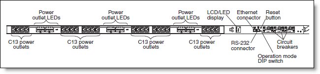
Figure 4. 0U Switched and Monitored PDUs with 24 C13 connectors
The 0U Switched and Monitored PDUs with 12 C13 and 12 C19 connectors (part number 46M4137 and 46M4134) have the components and controls as shown in Figure 5.
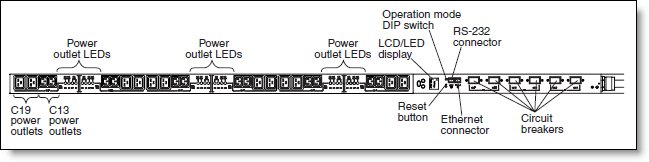
Figure 5. 0U Switched and Monitored PDUs with 12 C13 and 12 C19 connectors
The controls and components on these 0U PDUs are as follows:
- Power outlet LEDs. The power outlet LEDs indicate the receptacle status. An LED is steady when the receptacle is supporting load, and the LED is off when the receptacle is not supporting load.
- LCD display. The PDU provides information about the load status, events, measurements, identification, and settings through the front panel display, shown in Figure 6.
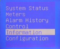
Figure 6. LCD display
Three buttons control the display: press Up and Down to navigate the menus; press OK to select the current menu or option. Holding Up navigates to the previous menu without saving.
- RS-232 connector. Connect a DB9-to-RJ-45 cable to this connector and to the serial (COM) connector on a computer, and use the computer as a configuration console.
- Ethernet connector. Use this connector to configure the PDU through a LAN. The Ethernet connector supports a 10/100 auto sensing network connection.
- Reset button. Use this button to reset the PDU for communication purposes only. Resetting the PDU does not affect the loads.
- Operation mode DIP switch. Use the DIP switch to set the mode of operation for the PDU: either normal operations or maintenance modes.
- Circuit breakers. If the load current rating of a power outlet exceeds 20 A, the associated circuit breaker is activated through a toggle handle or a toggle switch, depending on the PDU model. Power to the outlet is turned off automatically. To reset the circuit breaker, turn the breaker from Off to On.
Connectors and controls on the 1U PDUs
The 1U Switched and Monitored PDUs with three C13 and nine C19 connectors have the components and controls as shown in Figures 7 and 8.
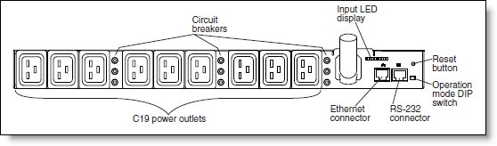
Figure 7. 1U Switched and Monitored PDU with 3 C13 and 9 C19 connectors (front)
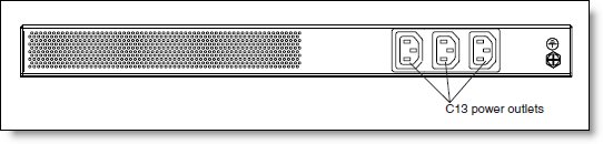
Figure 8. 1U Switched and Monitored PDU with 3 C13 and 9 C19 connectors (rear)
The controls and components on these 0U PDUs are as follows:
- Input LED display. The input LED display indicates the input power status.
Off: no input power. On: input power is normal. Flashing: input power is not normal. - RS-232 connector. Connect a DB9-to-RJ-45 cable to this connector and to the serial (COM) connector on a computer, and use the computer as a configuration console.
- Ethernet connector. Use this connector to configure the PDU through a LAN. The Ethernet connector supports a 10/100 auto-sensing network connection.
- Reset button. Use this button to reset the PDU for communication purposes only. Resetting the PDU does not affect the loads.
- Operation mode DIP switch. Use the DIP switch to set the mode of operation for the PDU: either normal operations or maintenance modes.
- Circuit breakers. If the load current rating of a power outlet exceeds 20 A, the associated circuit breaker is activated (the breaker pole pops out), and the power to the outlet is turned off automatically. To reset the circuit breaker, firmly press the breaker pole until it locks into place.
Environmental Monitoring Probe (EMP)
The EMP (part number 46M4113) is used to report local temperature and humidity values and make that information available to management tools such as Systems Director Active Energy Manager (AEM). The EMP connects to the PDU through the cable supplied with the EMP, as shown in Figure 9.
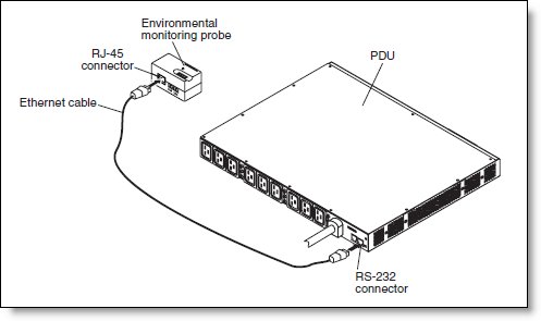
Figure 9. Environmental Monitoring Probe connected to the 1U Switched and Monitored PDU
The Environmental Monitoring Probe has the following features:
- Can be installed without having to turn off the PDU or the loads that are connected to it.
- Monitors temperature and humidity information of any environment that you want, to protect your critical equipment.
- Measures temperatures between 0°C and 80°C (32°F and 176°F) with an accuracy of ±1°C.
- Measures relative humidity between 10% and 90% with an accuracy of ±5%.
- Can be located away from the PDU with a Category 5 network cable up to 20 m (65.6 ft) long.
- Monitors the status of the two user-provided contact devices.
- Displays temperature, humidity, and contact closure status through a web browser.
- Allows user-selectable alarm thresholds to be defined for acceptable temperature or humidity limits.
- Supports email notification through SMTP when thresholds are exceeded or contact status changes.
- Logs changes in external contact status in the PDU event history log.
- Logs when temperature and humidity values exceed user-selectable limits in the PDU event history log.
Management tools
The PDU provides a graphical user interface that you can view from a web browser. Using a web browser, you can access and monitor the PDU power outlets and output devices remotely from a computer. Initial PDU setup is done though serial console connection.
The following tasks can be performed though Web interface:
- Control individual outlets (On/Off).
- Display PDU current, watts, output power in VA, power factor, and frequency.
- Display outlet level voltage, power factor and cumulative KW hour output.
- Set outlet alarm thresholds.
- View temperature and humidity status and set thresholds to trigger alarm notifications (1).
- Access a graphical historical view of PDU data for statistical trend analysis.
- View PDU Alarms.
- View Event/System Logs.
As an example, overall PDU statistics web page is shown on Figure 10.
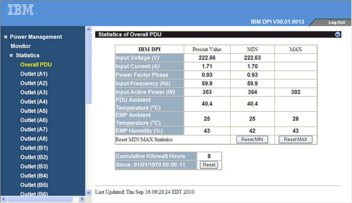
Figure 10. 0U and 1U Switched and Monitored PDUs web interface: overall PDU statistics
Systems Director Active Energy Manager (AEM)
AEM provides an array of new features that allow power and thermal trending analysis for improved power management. AEM collects power information for each device attached to an Switched and Monitored PDU, presenting a more complete view of energy usage within the data center.
The AEM helps in the following ways:
- Collect power information from each device attached to an Switched and Monitored PDU, thus presenting a more complete view of energy usage.
- With server consolidation plans, because of the increased server and rack power densities that have driven the requirement for advanced power management solutions.
- In combination with the optional Environmental Monitoring Probe, AEM enables cross-platform power and thermal trending analysis for improved power management. This configuration allows IT and facility managers to manage data centers for optimal energy efficiency, migrate workloads to eliminate hot spots, and transfer work from underutilized systems to conserve energy.
Active Energy Manager properties for PDU are shown on Figure 11.
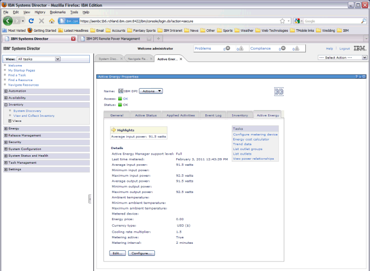
Figure 11. Active Energy Manager properties for PDU
Warranty
The 0U and 1U Switched and Monitored PDUs are offered with a one-year limited warranty. When installed in a Lenovo rack cabinet, these PDUs assume the rack’s base warranty and any warranty upgrade.
Supported rack cabinets
The 0U and 1U Switched and Monitored PDUs can be installed in the following racks:
- S2 42U Standard Rack cabinet (Types 9307, 9956)
- Enterprise Rack cabinet (Types 1410, 9308)
- 42U 1200mm Deep Dynamic Rack (Type 9360)
- 42U 1200mm Deep Static Rack (Type 9361)
- 47U 1200mm Deep Static Rack (Type 9362)
The 0U Switched and Monitored PDUs are designed to be installed vertically in side pockets of the rack. The Deep Dynamic and Deep Static racks support the button-mount design of the PDU and do not require additional hardware. Installation is shown in Figure 12. For the S2 42U Standard Rack and Enterprise Rack, the PDU part numbers include the necessary mounting hardware.
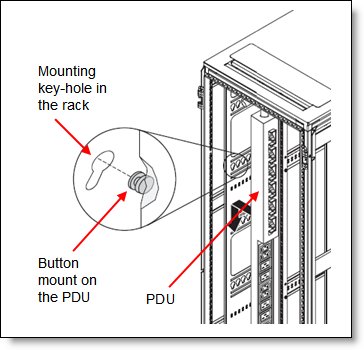
Figure 12. Installing the 0U PDU in a Deep Dynamic or Deep Static rack
Regulatory agency approvals
The PDU meets the following approvals:
- UL-60950/cUL
- CE (D.O.C.)
- IEC-60950
- CB Certificate and CB Test Report
- KC Korea
- FCC
- VCCI
- C-tick
- GOST
- ICES 003
Related product families
Product families related to this document are the following:
Trademarks
Lenovo and the Lenovo logo are trademarks or registered trademarks of Lenovo in the United States, other countries, or both. A current list of Lenovo trademarks is available on the Web at https://www.lenovo.com/us/en/legal/copytrade/.
The following terms are trademarks of Lenovo in the United States, other countries, or both:
Lenovo®
System x®
The following terms are trademarks of other companies:
IBM® is a trademark of IBM in the United States, other countries, or both.
Other company, product, or service names may be trademarks or service marks of others.


