

Top
Abstract
The Lenovo zero-U (0U) Switched and Monitored power distribution units (PDUs) are the ideal solutions when you need flexible, reliable, easy-to-deploy power distribution with branch circuit protection to minimize downtime. These rack-dense units distribute power to up to 42 outlets. The 0U PDUs are designed to be installed vertically in the rear channel or side pockets of a Lenovo rack, thereby not consuming any horizontal rack space.
This product guide provides essential presales information to understand the 0U Switched and Monitored PDUs and their key features, specifications, and compatibility. This guide is intended for technical specialists, sales specialists, sales engineers, IT architects, and other IT professionals who want to learn more about the Switched and Monitored PDUs and consider their use in IT solutions.
Change History
Changes in the October 24, 2024 update:
- The following PDU is is now withdrawn from marketing.
- 0U 20 C13/4 C19 Switched and Monitored 24A 1 Phase PDU (30A derated), 00YJ781
Introduction
The Lenovo zero-U (0U) Switched and Monitored power distribution units (PDUs) are the ideal solutions when you need flexible, reliable, easy-to-deploy power distribution with branch circuit protection to minimize downtime. These rack-dense units distribute power to up to 42 outlets. 0U PDUs are designed to be installed vertically in the rear channel or side pockets of a Lenovo rack, thereby not consuming any horizontal rack space that otherwise be used by servers, storage and network switches (hence the term 0U).
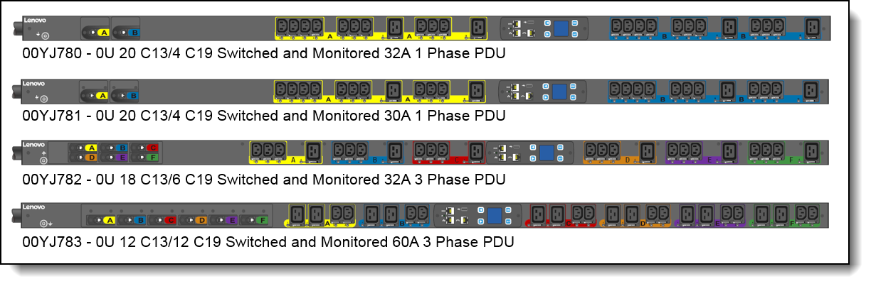
The following figure displays the 0U Switched and Monitored PDUs.
Did you know?
With ever growing power densities in today’s rack environments, it is all too easy to add load in the wrong place and trigger an overload event. The 0U Switched and Monitored PDU offerings can minimize this impact, providing the ability to quickly recover with resettable circuit breakers for each designated bank of receptacles, referred to as load groups. Breakers are color coded to the receptacles in a particular load group to aid in configuration, installation, and maintenance. Furthermore, these PDUs also offer individual outlet remote monitoring and switching (on/off), which allows for remote power sequencing and further helping to prevent unintended PDU overloading.
Introduction to PDUs
A power distribution unit (PDU) is a highly reliable, multiple outlet power strip designed to consolidate line cords within the rack and distribute conditioned power from an uninterruptible power supply (UPS) or utility power to servers and other IT equipment. The PDU efficiently distributes power within the rack and provides fault-tolerant power redundancy for high availability requirements.
There are three types of PDUs available from Lenovo: basic, monitored, and switched & monitored. The PDUs covered in this document are of the switched & monitored type.
- Basic PDUs: The simplest and most cost-effective power distribution. Available with various outlet configurations and line cord options to support different systems and load requirements.
- Monitored PDUs: provides the same benefits as a Basic PDU, but adds additional advanced PDU power monitoring down to the load group. This enables businesses to have a cross-platform rack-level power and thermal view for trending analysis to improve power management
- Switched & monitored PDUs: These are advanced power management solutions, providing power monitoring at the outlet level, with increased accuracy at low amperages, for more precise views of power consumption down to the individual server level instead of at the consolidated load group. These PDUs also offer management via a web-based interface which includes individual outlet switching (on/off). Outlet switching allows for remote power sequencing and helps prevent unintended PDU overloading.
Part number information
The following table provides the ordering part numbers and feature codes for the 0U Switched and Monitored PDUs.
| Part number |
Feature code |
Description | Region availability* |
|---|---|---|---|
| 00YJ780 | AU01 | 0U 20 C13/4 C19 Switched and Monitored 32A 1 Phase PDU | International |
| 00YJ781** | AU03 | 0U 20 C13/4 C19 Switched and Monitored 24A 1 Phase PDU (30A derated) | North America |
| 00YJ782 | AU02 | 0U 18 C13/6 C19 Switched and Monitored 32A 3 Phase PDU | International |
| 00YJ783 | AU04 | 0U 12 C13/12 C19 Switched and Monitored 48A 3 Phase PDU (60A derated) | North America |
| 46M4113 | 6146 | Enviromental Monitoring Probe | All countries |
* See region availability below
** Replacement: 4PU7A93179
Region availability
PDUs indicated in Table 1 as available for North America are available in the following countries:
- United States
- Canada
- Mexico
- Saudi Arabia
- Japan
- Philippines
- Some of Brazil
PDUs indicated in Table 1 as available Internationally are available in these regions:
- Europe
- Africa
- Most of the Middle East
- Most of Asia
- Australia/New Zealand
- Most of South America
Included with the PDUs
The PDUs include the following items:
- One Power Distribution Unit with an attached power cord
- Two spare black plastic key hole buttons for securing clip feet on rack
- Mounting hardware
- Adhesive power feed labels: 1x blue arrow and 1x red arrow (to indicate power source flow)
- PDU warranty poster
- Safety CD
- Important notice
- Quick start guide
- Serial cable (RJ-45 to DB9)
- Ethernet cable, 60cm
- RJ-45 Y-splitter adapter for daisy chaining PDUs
- MAC Address information
Features and specifications
The 0U Switched & Monitored PDUs have the following common features:
- Address-specific IP security masks to prevent unauthorized access
- Comprehensive power management and flexible configuration through a web browser, NMS, Telnet, SNMP, or HyperTerminal (console)
- Configurable user-security control
- Daily history report through email
- Detailed data-logging for statistical analysis and diagnostics
- Easy-to-use interface to display input and output status
- Event notification through SNMP trap or email alerts
- Monitoring of the PDU locally or remotely through a console or network
- Remote monitoring of connected devices and sensors
- Support for Uninterruptable Power Supply Protector (UPP) and Uninterruptable Power Supply Manager (UPM) software.
The following table compares the technical and environmental specifications of the 0U Switched and Monitored PDUs.
| Feature | 0U 20 C13/4 C19 Switched and Monitored 32A 1 Phase PDU | 0U 20 C13/4 C19 Switched and Monitored 24A 1 Phase PDU | 0U 18 C13/6 C19 Switched and Monitored 32A 3 Phase PDU | 0U 12 C13/12 C19 Switched and Monitored 48A 3 Phase PDU |
|---|---|---|---|---|
| Part Number | 00YJ780 | 00YJ781 | 00YJ782 | 00YJ783 |
| Feature Code | AU01 | AU03 | AU02 | AU04 |
| Region | International | North America | International | North America |
| Input power | ||||
| Number of phases | Single phase input | Single phase input | Three phase input | Three phase input |
| Line cord | Attached line cord, 3 m length (9-ft, 10-in) | Attached line cord, 3 m length (9-ft, 10-in) | Attached line cord, 3 m length (9-ft, 10-in) | Attached line cord, 3 m length (9-ft, 10-in) |
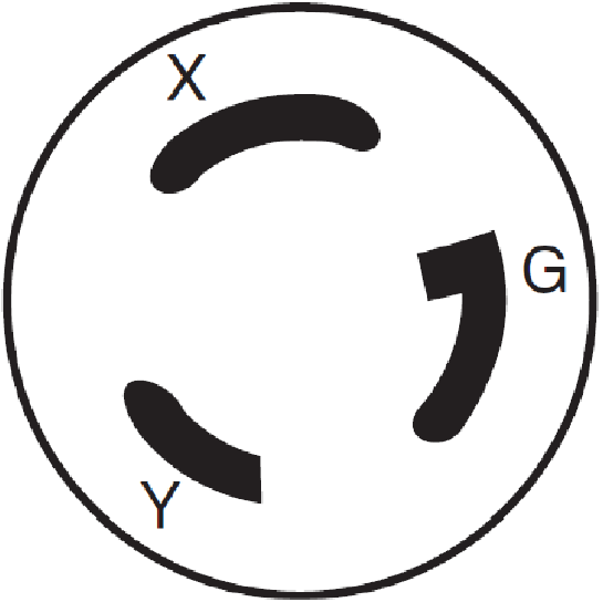
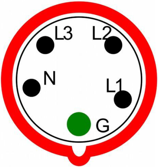
| Line cord connector | 332P6, W+N+PE 1ph | NEMA L6-30P | 532P6, WYE, 3W+N+PE 3Ph | HBL460P9, Delta 3W+PE 3ph |
| Plug design | 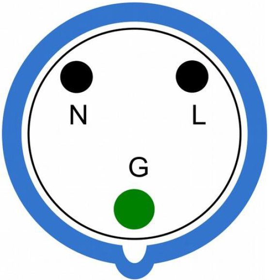 |
 |
 |
 |
| Input voltage | 200-240V | 200-240V | 200-240V / 350-415V |
200-240V |
| Input current | 32A | 24A (derated from 30A) | 32A | 48A (derated from 60A) |
| Maximum power rating | 7680 VA | 5760 VA | 23,040 VA | 20,736 VA |
| Output power | ||||
| Number of C13 outlets | 20 | 20 | 18 | 12 |
| Number of C19 outlets | 4 | 4 | 6 | 12 |
| Output voltage rating at 50/60Hz | 200-240V | 200-240V | 200-240V | 200-240V |
| Output current rating | Each C13 outlet: 10 amps; Each C19 outlet: 16 amps | Each C13 outlet: 10 amps; Each C19 outlet: 16 amps | Each C13 outlet: 10 amps; Each C19 outlet: 16 amps | Each C13 outlet: 10 amps; Each C19 outlet: 16 amps |
| Circuit breakers | Two double-pole branch rated circuit breakers rated at 16A | Two double-pole branch rated circuit breakers rated at 16A | Six double-pole branch rated circuit breakers rated at 16A | Six double-pole branch rated circuit breakers rated at 16A |
| Number of load groups | 2 (A, B) | 2 (A, B) | 6 (A-F) | 6 (A-F) |
| Number of outlets per load group | A = 10x C13, 2x C19 B = 10x C13, 2x C19 |
A = 10x C13, 2x C19 B = 10x C13, 2x C19 |
A = 3x C13, 1x C19 B = 3x C13, 1x C19 C = 3x C13, 1x C19 D = 3x C13, 1x C19 E = 3x C13, 1x C19 F = 3x C13, 1x C19 |
A = 2x C13, 2x C19 B = 2x C13, 2x C19 C = 2x C13, 2x C19 D = 2x C13, 2x C19 E = 2x C13, 2x C19 F = 2x C13, 2x C19 |
| Capacity per load group (Amps) | A = 16 A B = 16 A |
A = 20 A B = 20 A |
A = 20 A B = 20 A C = 20 A D = 16 A E = 16 A F = 16 A |
A = 20 A B = 20 A C = 20 A D = 20 A E = 20 A F = 20 A |
| Capacity per phase (Amps) | Not applicable | Not applicable | 32 A | 32 A |
| Capacity per PDU (Amps) | 32 A | 24 A | 96 A | 86 A |
| Mechanical and environmental | ||||
| Physical dimensions (DxWxH) | 2.5 x 2.0 x 66.4 in 66 x 52 x 1689 mm |
2.5 x 2.0 x 66.4 in 66 x 52 x 1689 mm |
3.9 x 2.0 x 66.4 in 100 x 52 x 1689 mm |
5.1 x 2.0 x 66.4 in 131 x 52 x 1689 mm |
| Weight | 5 kg / 11 lb | 5.1 kg / 11.2 lb | 6.9 kg / 15.2 lb | 10.5 kg / 23.1 lb |
| Operating temperature | 10° C to 60° C 50° F to 140° F |
10° C to 55° C 50° F - 122° F |
10° C to 60° C 50° F to 140° F |
10° C to 55° C 50° F - 122° F |
| Operating humidity | 5% to 95% without condensation | 5% to 95% without condensation | 5% to 95% without condensation | 5% to 95% without condensation |
Connectors and load groups
The 0U Switched and Monitored PDUs with 20 C13 connectors and 4 C19 connectors (part numbers
00YJ780 and 00YJ781) has the components and controls as shown in the following figure.
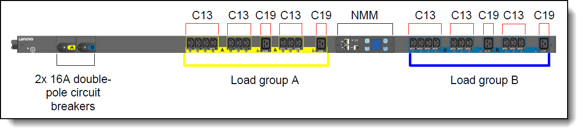
Figure 2. Load groups for part numbers 00YJ780 and 00YJ781
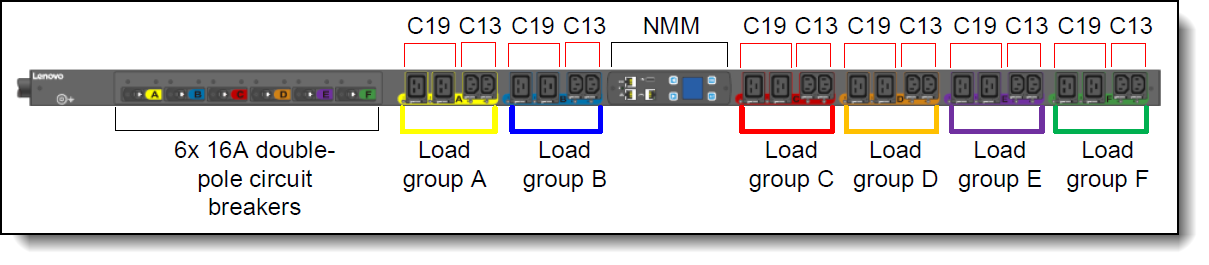
The 0U Switched and Monitored PDU with 18 C13 connectors and 6 C19 connectors (part number 00YJ782) has the components and controls as shown in the following figure.

Management interface
The switched and managed PDUs include Network Management Module (NMM) that provides the interface and connectors to manage the PDU. The following figure shows the LCD screen and the ports of the NMM. The LCD interface provides information about the load status, events, measurements, identification, and settings.
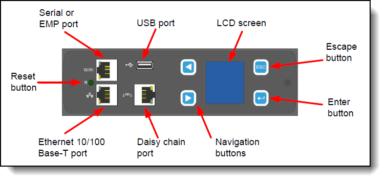
Figure 5. Interface of the Network Management Module
The components of the NMM are as follows:
- LCD screen and navigation buttons: There are four buttons surrounding the LCD screen that control the display; press the up and down buttons to navigate the menus; press the Enter button to select the current menu or option; press the ESC button return to the previous menu without saving. The LCD screen in a dual color display and rotates 90°, 180°, and 270° for enhanced reading capability.
- Reset button: Use this button to reset the PDU for communication purposes only. Resetting the PDU does not affect the outlets/loads.
- Serial or EMP port: Use this port to open a serial connection to the PDU from your laptop. This port is also used to connect the Environmental Monitoring Probe (EMP) to the PDU. Note: the EMP is now withdrawn from marketing. See the following section for information the EMP.
- USB port: Use the USB connection to upgrade firmware and configuration file download/upload.
- Ethernet 10/100 Base-T port. Use this connector to configure the PDU through a LAN. The Ethernet connector supports a 10/100 auto sensing network connection.
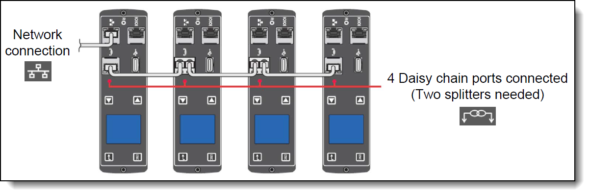
- Daisy chain port: Use this port to daisy chain two PDUs together. This enables multiple PDUs to connect over one Ethernet port. Up to eight PDUs can be daisy chained using an external ‘Y’ RJ45 adapter. The following figure shows how the RJ-45 Y-splitter adapters (one included with each PDU) can be used. In the figure, the use of two Y-splitters and three Ethernet cables means that four PDUs can be daisy chained together and all managed from the one network connection.
Environmental Monitoring Probe
The Environmental Monitoring Probe (EMP), part number 46M4113, is an optional device used to report local temperature and humidity values at its installed location and make that information available to the web interface of the PDU. The EMP connects to the PDU via the EMP/Serial port of the NMM that is installed in the PDU. The following figure displays the EMP.
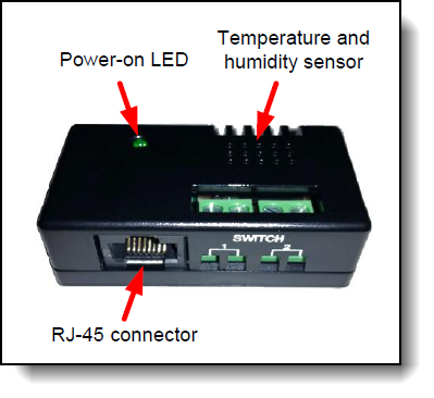
Figure 7. Environmental Monitoring Probe
The Environmental Monitoring Probe has the following features:
- Can be installed without having to turn off the PDU or the loads that are connected to it.
- Monitors temperature and humidity information of any environment that you want, to protect your critical equipment.
- Measures temperatures 0° C to 80° C (32° F to 176° F) with an accuracy of ±1° C.
- Measures relative humidity between 10% and 90% with an accuracy of ±5%.
- Can be located away from the PDU with a Category 5 network cable up to 20 m (65.6 ft) long.
- Monitors the status of the two user-provided contact devices.
- Displays temperature, humidity, and contact closure status through a web browser.
- Allows user-selectable alarm thresholds to be defined for acceptable temperature or humidity limits.
- Supports email notification through SMTP when thresholds are exceeded or contact status changes.
- Logs changes in external contact status in the PDU event history log.
- Logs when temperature and humidity values exceed user-selectable limits in the PDU event history log.
Browser interface
The PDU provides a graphical user interface that you can view from a web browser. Using a web browser, you can access and monitor the PDU power outlets and output devices remotely from a computer.
The following tasks can be performed though browser interface:
- Control individual outlets (On/Off)
- Display PDU current, watts, output power in VA, power factor, and frequency
- Display outlet level voltage, power factor and cumulative KW hour output
- Set outlet alarm thresholds
- View temperature and humidity status where the PDU is located and set thresholds to trigger alarm notifications
- View EMP temperature and humidity status where the EMP is located (Note: The EMP is now withdrawn from marketing)
- Access a graphical historical view of PDU data for statistical trend analysis
- View PDU Alarms
- View Event/System Logs
Selecting the right PDU
To avoid over sizing or under sizing power, it is important to understand the power requirements of the hardware that will be powered by the PDU(s). The tool can be leveraged online from https://datacentersupport.lenovo.com/us/en/solutions/lnvo-lcp
Likewise, to avoid over sizing or under sizing PDUs it is also important to understand the PDU capabilities and capacities.
Consider the following for capabilities:
- Do you require monitoring and/or outlet switching? If so, then consider the switched and monitored PDUs described here. If not, consider the Basic PDUs described at at http://lenovopress.com/lp0576.
- Do you require environmental monitoring capabilities? If so, then consider the switched and monitored PDUs described here. If not, consider the Basic PDUs described at at http://lenovopress.com/lp0576.
- Does the PDU have the right type of power for your scenario? For example, 16A, 30A, 32A, 63A and single or three phase power?
- Does the PDU have enough of the correct type of outlets for your scenario?
Consider the following for capacities:
- Will each outlet be able to support the load being connected to it? For example, C13 outlets have a 10A limit.
- Will each load group be able to support the hardware being connected to it?
- Will each phase, where applicable, be able to support the hardware being connected to it?
- Is the overall power capacity of the PDU able to support the hardware being connected to it?
- Do you have enough PDUs to be N+N or N+1 redundancy if this is required?
The Lenovo Capacity Planner (LCP) is a useful tool to determine the power draw of other devices such as storage and switching that will be attached to the PDUs, refer to the products user manual for the maximum power draw.
Supported rack cabinets
The 0U Switched and Monitored PDUs can be installed in all 19 inch rack cabinets.
- For specifications about racks supporting 0U PDUs, see the Lenovo Rack Cabinet Reference, available from:
https://lenovopress.lenovo.com/lp1287-lenovo-rack-cabinet-reference#0u-pdu-support=0U%2520PDU
Each PDU has a universal mounting bracket that enables the PDU to be mounted in a variety of different racks that are outside of the Lenovo portfolio.
The PDU is designed to be mounted without the use of tools. Mounting buttons are pre-installed on the rear of the PDU at the factory. The mounting buttons allow for three mounting methods for installing the 0U Switched and Monitored PDUs vertically in a rack.
- Using factory-installed buttons on the PDU to mount the PDU in keyhole openings in the rack frame
- Using buttons on clip feet to mount the PDU in keyhole openings in the rack frame
- Using clip feet and cage nuts secured to the rack to mount the PDU onto the clip
For additional information on racking the 0U Switched and Monitored PDUs, refer to User’s Guide for the PDUs.
Warranty
The 0U Switched and Monitored PDUs are offered with a three-year limited warranty. At Lenovo discretion this warranty will be either CRU service (customer replaceable unit) or a Lenovo employee, subcontractor or reseller will be assigned to repair the failing item. Proof and date of purchase is required for warranty claims.
Agency approvals
The PDUs conform to the following standards:
- Circuit breaker UL489 approval
- Circuit breaker IEC/EN60934 approval
- Outlet standard: IEC C13-C19: UL498 and IEC 60320
- 00YJ780 - CB, EAC, KC, CE, RCM
- 00YJ781 - cUL-US, CB, FCC, VCCI
- 00YJ782 - CB, EAC, KC, CE, RCM
- 00YJ783 - cUL-US, CB, FCC, VCCI
Related product families
Product families related to this document are the following:
Trademarks
Lenovo and the Lenovo logo are trademarks or registered trademarks of Lenovo in the United States, other countries, or both. A current list of Lenovo trademarks is available on the Web at https://www.lenovo.com/us/en/legal/copytrade/.
The following terms are trademarks of Lenovo in the United States, other countries, or both:
Lenovo®
Other company, product, or service names may be trademarks or service marks of others.


