

Top
Author
Published
30 May 2025Form Number
LP2227PDF size
16 pages, 1.3 MBSubscribed to LP2227.
Thank you for your feedback.
Abstract
This document describes how to configure the ConnectX-8 800Gb adapters to use an auxiliary cable to provide a PCIe Gen5 x32 host interface.
Introduction
The NVIDIA ConnectX-8 800Gb adapters require a PCIe Gen6 x16 or PCIe Gen5 x32 host interface to maximize performance of the adapter. On PCIe Gen5 servers such as the ThinkSystem V4 servers, a x32 host interface is achieved through the use of both the x16 interface of the adapter's edge connector plus a x16 auxiliary cable which connects to an adjacent slot in the server.
By default, the ConnectX-8 adapters are configured to only use the x16 host interface of the adapter itself. In order to use the auxiliary cable, settings in the adapter will need to be changed. This document explains the steps how to configure the adapter operating mode, so that the x16 connector of the auxiliary cable is also enabled.
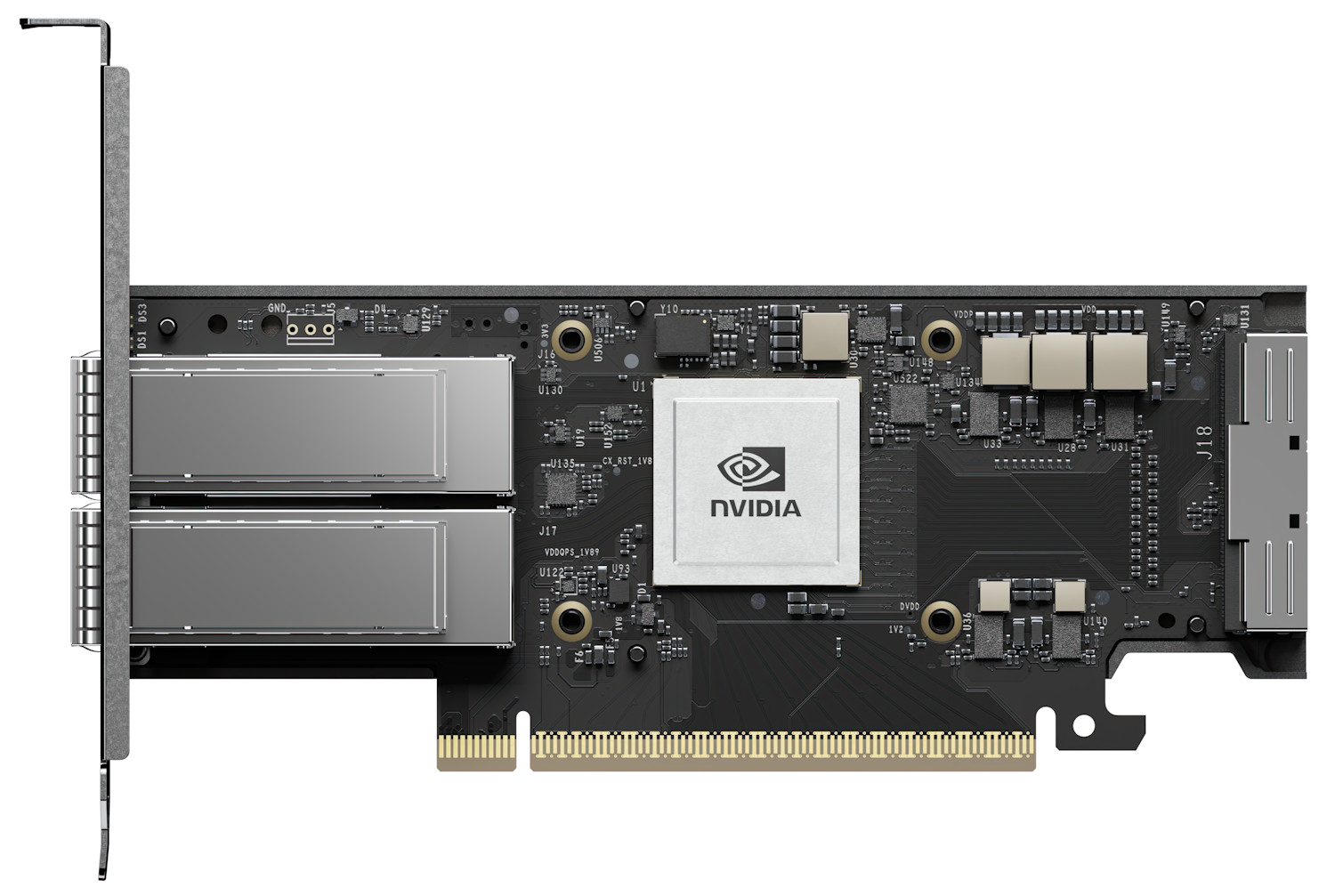
Figure 1. ThinkSystem NVIDIA ConnectX-8 8240 Adapter with x16 edge connector and x16 auxiliary cable connector
The default Gen6 x16 mode of the adapter does not auto-negotiate to Gen5 x32 due to firmware constraints because the Socket Direct function is not able to automatically detect when the Auxiliary cable is connected. As a result, manual configuration is required, as documented in this paper.
Socket Direct: If you are planning to use the Socket Direct of the adapters, you will also need to follow these instructions to enable the Gen5 x32 host connectivity. Socket Direct enables direct access from two CPUs, each with a x16 host interface. One processor connects through the x16 edge connector of the adapter and the other processor connects through a x16 auxiliary cable connected to the adapter.
Applicable adapters
This document applies to the adapters and auxiliary cable listed in the following table
Prerequisites
Ensure that the adapter and cable are installed in supported slots. Consult the server product guide to verify:
A list of product guides of supported servers can be found in the following link:
https://lenovopress.lenovo.com/search#term=8180%2520or%25208240&resource_type=product-guide&sort=relevance
Installing the tools
Configuring the CX8 operating mode requires the use of NVIDIA's command-line tools, mst and mlxconfig. Both commands are required for this procedure, and are part of the NVIDIA DOCA downloadable package.
To install NVIDIA DOCA, perform the following steps.
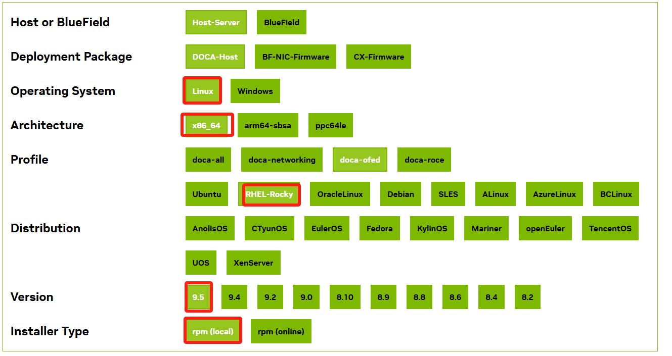
- Download the DOCA package from:
https://developer.nvidia.com/doca-downloads?deployment_platform=Host-Server&deployment_package=DOCA-Host - Make the selections on the web page appropriate for your server:
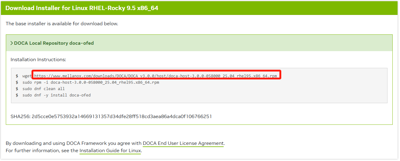
- You'll then be prompted for installation instructions, similar to the following figure.
Parameters of the mlxconfig command
In the next section, we'll be using the mlxconfig command to configure the adapter to operate in PCIe Gen5 x32 mode. The commands we'll use are the following:
# mlxconfig -d devicename -y set PCIE_CREDIT_TOKEN_TIMEOUT=0
# mlxconfig -d devicename -y set PCI_BUS00_WIDTH=5
# mlxconfig -d devicename -y set PCI_BUS00_SPEED=4
# mlxconfig -d devicename -y set PCI_BUS00_HIERARCHY_TYPE=0
# mlxconfig -d devicename -y set PCI_BUS10_WIDTH=5
# mlxconfig -d devicename -y set PCI_BUS10_SPEED=4
# mlxconfig -d devicename -y set PCI_BUS10_HIERARCHY_TYPE=0
In these commands, device name is the name of configuration node for the CX8 adapter. In our example, as shown in the mst status command, is /dev/mst/mt4131_pciconf0.
The values after the -y set parameter are used to configure the adapter, and are listed in the following table.
Configuring the adapter
Now that the tools are installed, use the following procedure to configure the adapter to have a PCIe Gen5 x32 host interface.
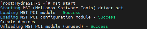
- To begin, run the following command to create the devices
# mst start -
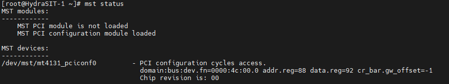
Check which adapters are installed on the server by running the following command:
# mst statusIn this output, you can see that there is only one adapter card on one PCI slot.
- Run lspci to verify the card types
# lspci | grep Mellanox - Run the following lspci command using the device number from Figure 4, to determine the current mode that the adapter is running in.
# lspci -s 4c:00.0 -vvVersion of lspci: Only recent versions of the pciutils package (which includes lspci) can recognize the rate of PCIe Gen6. Versions of lspci 3.10.0 and above have been tested and confirmed to support PCIe Gen6, however the inbox version of pciutils does not support Gen6.
Download the latest pciutils from https://github.com/pciutils/pciutils. If your OS is connected to the remote YUM repository, it can be upgraded online.
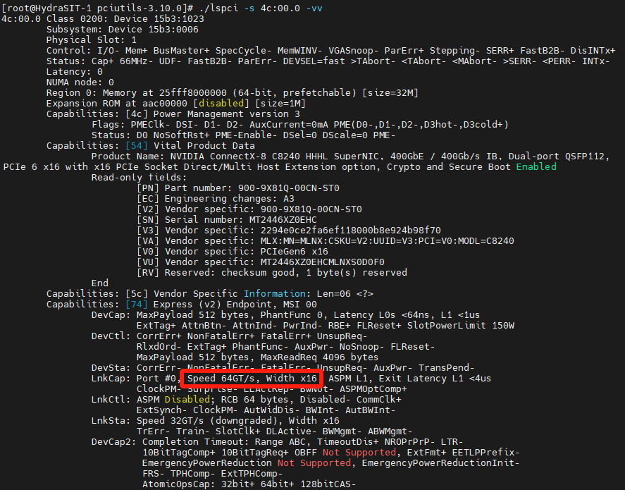
Figure 7. PCI capabilities of adapterThe values highlighted Speed 64GT/s, Width x16 indicates that the adapter is currently configured to operating in the Gen6 x16 mode.
The output of the mst status command (Figure 5) includes the name of configuration node for the CX8 adapter. In our example, it is /dev/mst/mt4131_pciconf0. This value is used in the commands in the next steps.
Command syntax: For details about the mlxconfig commands used in the following steps, see the Parameters of the mlxconfig command section.
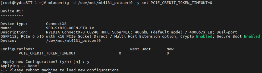
- Set the adapter adjust the timeout of PCIe credit using the following command, as shown in the following figure.
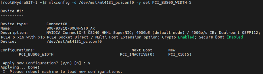
# mlxconfig -d /dev/mst/mt4131_pciconf0 -y set PCIE_CREDIT_TOKEN_TIMEOUT=0 - Set the CX8 adapter to the PCIe bandwidth of x16 using the following command, as shown in the following figure
# mlxconfig -d /dev/mst/mt4131_pciconf0 -y set PCI_BUS00_WIDTH=5 - Set the CX8 adapter to the PCIe Gen5 using the following command, as shown in the following figure.
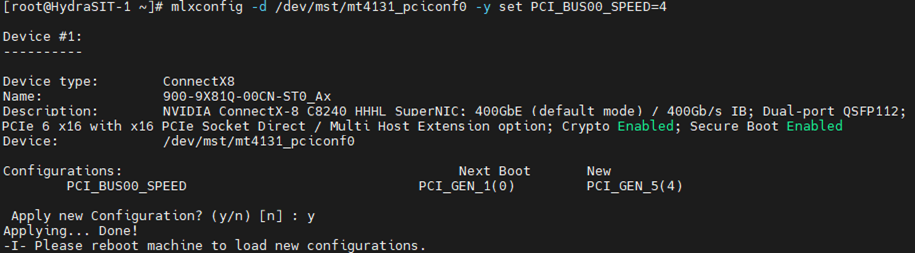
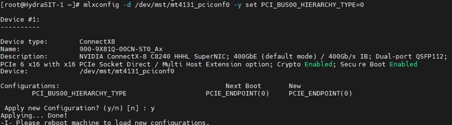
# mlxconfig -d /dev/mst/mt4131_pciconf0 -y set PCI_BUS00_SPEED=4 - Set the CX8 adapter’s hierarchy as PCIe endpoint using the following command, as shown in the following figure.
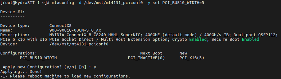
# mlxconfig -d /dev/mst/mt4131_pciconf0 -y set PCI_BUS00_HIERARCHY_TYPE=0 - Set the auxiliary cable connection to the PCIe bandwidth of x16 using the following command, as shown in the following figure.
# mlxconfig -d /dev/mst/mt4131_pciconf0 -y set PCI_BUS10_WIDTH=5 - Set the auxiliary cable connection to the PCIe Gen5 using the following command, as shown in the following figure.
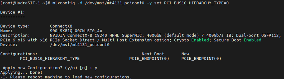
# mlxconfig -d /dev/mst/mt4131_pciconf0 -y set PCI_BUS10_SPEED=4 - Set the auxiliary cable connection’s hierarchy as PCIe endpoint using the following command, as shown in the following figure.
# mlxconfig -d /dev/mst/mt4131_pciconf0 -y set PCI_BUS10_HIERARCHY_TYPE=0 -
Restart the server to ensure the commands take effect.


Verifying the configuration
To verify that the adapter is now configured for PCIe Gen5 x32 mode, perform the following steps:
-
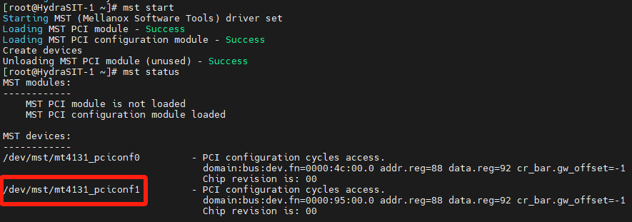
Run the mst start and mst status commands. You should see in the out that there is now an additional device, as highlighted in the following figure.
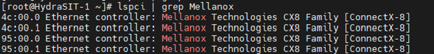
mst start mst status - Executing the lspci command reveals an additional device, as shown in the following figure.
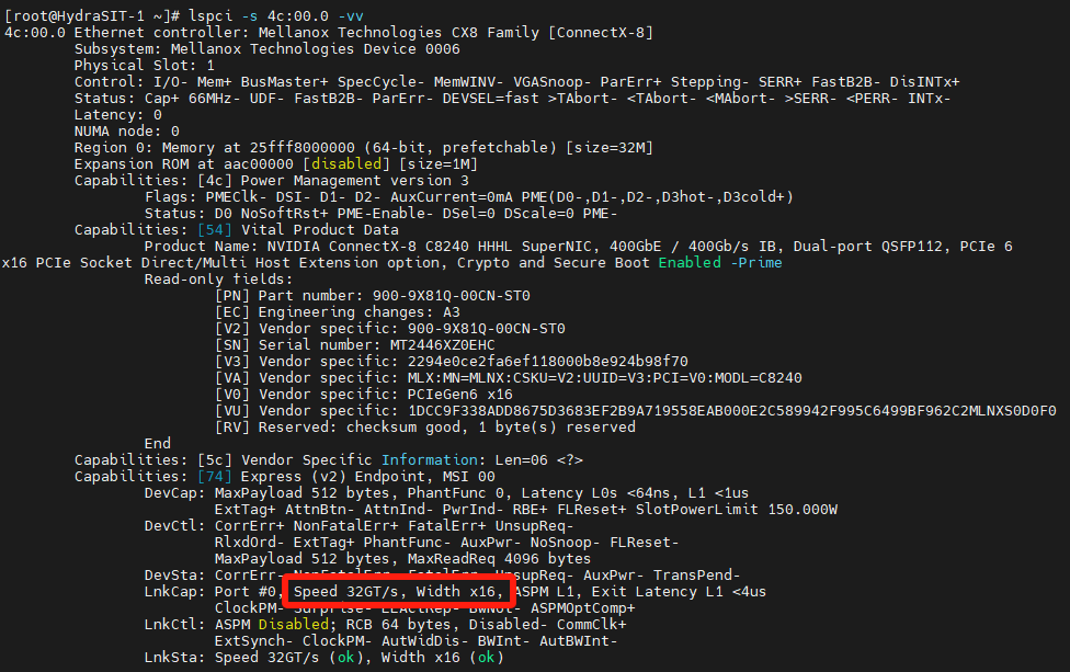
# lspci | grep Mellanox - Verify that the ConnectX-8 adapter, which becomes Gen5 x16, as shown in the following figure. The value of the -s parameter comes from the output in Step 1. Verify that the output says "Speed 32GT/s, Width x16" as highlighted.
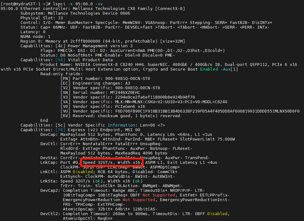
# lspci -s 4c:00.0 -vv - Retrieve the PCIe properties of Auxiliary Cable, which should now be Gen5 x16, as shown in the following figure. The value of the -s parameter comes from the output in Step 1. Verify that the output says "Speed 32GT/s, Width x16" as highlighted.
# lspci -s 95:00.0 -vv
Resources
For more information, see the following web pages:
- Product Guide: ThinkSystem NVIDIA ConnectX-8 8180 800Gbs OSFP PCIe Gen6 x16 Adapter
https://lenovopress.lenovo.com/lp2163-thinksystem-nvidia-connectx-8-8180-800gbs-osfp-pcie-gen6-x16-adapter - Product Guide: ThinkSystem NVIDIA ConnectX-8 8240 400Gbs QSFP112 2-Port PCIe Gen6 x16 Adapter
https://lenovopress.lenovo.com/lp2164-thinksystem-nvidia-connectx-8-8240-400gbs-qsfp112-2-port-pcie-gen6-x16-adapter - NVIDIA User Manuals
https://docs.nvidia.com/networking/index.html
Author
Liyong Duan is a Lenovo Senior Engineer responsible for NVIDIA Ethernet adapters in Lenovo ThinkSystem servers. Liyong Duan has worked in the IT industry since 2020, and is currently based in Tianjinn, China.
Trademarks
Lenovo and the Lenovo logo are trademarks or registered trademarks of Lenovo in the United States, other countries, or both. A current list of Lenovo trademarks is available on the Web at https://www.lenovo.com/us/en/legal/copytrade/.
The following terms are trademarks of Lenovo in the United States, other countries, or both:
Lenovo®
ThinkSystem®
Other company, product, or service names may be trademarks or service marks of others.
Configure and Buy
Please select a locale
Full Change History
Course Detail
Employees Only Content
The content in this document with a is only visible to employees who are logged in. Logon using your Lenovo ITcode and password via Lenovo single-signon (SSO).
The author of the document has determined that this content is classified as Lenovo Internal and should not be normally be made available to people who are not employees or contractors. This includes partners, customers, and competitors. The reasons may vary and you should reach out to the authors of the document for clarification, if needed. Be cautious about sharing this content with others as it may contain sensitive information.
Any visitor to the Lenovo Press web site who is not logged on will not be able to see this employee-only content. This content is excluded from search engine indexes and will not appear in any search results.
For all users, including logged-in employees, this employee-only content does not appear in the PDF version of this document.
This functionality is cookie based. The web site will normally remember your login state between browser sessions, however, if you clear cookies at the end of a session or work in an Incognito/Private browser window, then you will need to log in each time.
If you have any questions about this feature of the Lenovo Press web, please email David Watts at dwatts@lenovo.com.


