

Top
Abstract
The Flex System X6 Compute Node, machine type 7903, is a high-performance scalable compute node that is designed to take on the most demanding workloads. The performance, flexibility, and resiliency features enable the X6 to run mission-critical workloads, such as key business applications, database, analytics, and large virtual machine deployments.
The X6 Compute Node family is composed of the x880 X6, x480 X6, and x280 X6. Each compute node contains two Intel Xeon E7 processors. The x880 X6 uses E7-8800 v2 processors and supports joining two or four x880 compute nodes together to form a single 8-socket server with 192 DIMM slots. The x480 uses E7-4800 v2 processors and supports joining two x480 compute nodes together to form a single 4-socket server with 96 DIMM slots. The x280 has two E7-2800 v2 processors and 48 DIMM slots but does not offer scaling.
Suggested use: Mission-critical scalable databases, business analytics, virtualization, enterprise applications, and cloud applications.
Note: This Product Guide describes the models of the Flex System X6 Compute Nodes, machine type 7903. For machine type 7196, see the Lenovo Press Product Guide Lenovo Flex System X6 Compute Node (7196).
Note: The Flex System X6 Compute Nodes, machine type 7903, are now withdrawn from marketing.
Learn how easy it is to scale the X6 Compute Nodes with Simon Casey
Introduction
The Flex System X6 Compute Node, machine type 7903, is a high-performance scalable compute node that is designed to take on the most demanding workloads. The performance, flexibility, and resiliency features enable the X6 to run mission-critical workloads, such as key business applications, database, analytics, and large virtual machine deployments.
The X6 Compute Node family is composed of the x880 X6, x480 X6, and x280 X6. Each compute node contains two Intel Xeon E7 processors. The x880 X6 uses E7-8800 v2 processors and supports joining two or four x880 compute nodes together to form a single 8-socket server with 192 DIMM slots. The x480 uses E7-4800 v2 processors and supports joining two x480 compute nodes together to form a single 4-socket server with 96 DIMM slots. The x280 has two E7-2800 v2 processors and 48 DIMM slots but does not offer scaling.
Suggested use: Mission-critical scalable databases, business analytics, virtualization, enterprise applications, and cloud applications.
Figure 1 shows the Flex System X6 Compute Node.
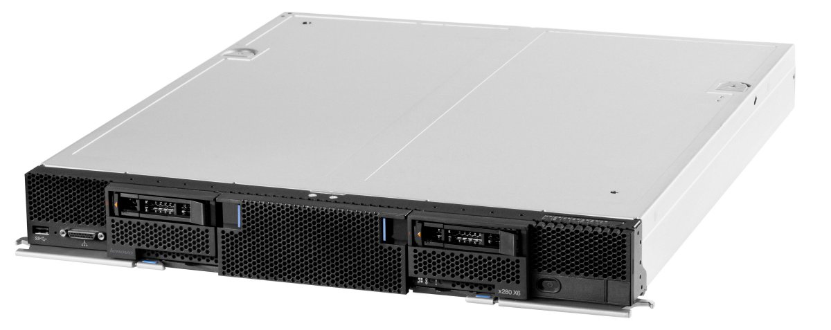
Figure 1. Flex System X6 Compute Node
Did you know?
If you are using an application that requires significant computing power and you value the integration of components that Flex System offers, then the X6 Compute Node family is an excellent choice. It offers the performance and reliability of the Intel Xeon E7 processor family, plus significant memory and I/O capacity, and lets you easily scale from two sockets all the way to eight sockets by simply adding more compute nodes and using the appropriate scalability connector on the front of the server.
Key features
The increasing demand for cloud-computing and analytics workloads by enterprises to meet social, mobile, and big data requirements drives innovation to find new ways to build informational systems. Clients are looking for cost-optimized and fit-for-purpose IT solutions that manage large amounts of data, easily scale performance, and provide enterprise class reliability.
Built on decades of innovation, Lenovo introduces its sixth generation of Enterprise X-Architecture® technology into the Flex System ecosystem with the announcement of the Flex System X6 family of compute nodes. Like their rack-mount counterparts, the System x3850 X6 and x3950 X6, Flex System X6 Compute Nodes are fast, agile, and resilient:
- Fast application performance means immediate access to information.
- Agile system design helps reduce acquisition costs and provides the ability to upgrade processor and memory technology at each refresh within the same chassis.
- Resilient platforms maximize application uptime and promote easy integration in virtual environments.
X6 servers continue to lead the way as the shift toward mission-critical scalable databases, business analytics, virtualization, enterprise applications, and cloud-computing applications accelerates.
Fast application performance
Each compute node offers numerous features to boost performance:
- Based on the Intel Xeon processor E7 v2 product family, which improves productivity by offering superior system performance:
- Two processors in each compute node, which are scalable up to eight processors in four compute nodes.
- Each processor has up to 15 cores and 37.5 MB of L3 cache, depending on the processor that is selected.
- Processors operate at up to 3.4 GHz.
- Memory bus speeds up to 1600 MHz.
- QPI links between processors up to 8 GTps.
- Supports up to 48 DIMM sockets, with 24 DIMMs per processor.
- Intelligent and adaptive system performance with Intel Turbo Boost Technology 2.0 allows processor cores to run at maximum speeds during peak workloads by temporarily going beyond processor thermal design power (TDP).
- Intel Hyper-Threading Technology boosts performance for multi-threaded applications by enabling simultaneous multi-threading within each processor core, up to two threads per core.
- Intel Virtualization Technology integrates hardware-level virtualization hooks that allow operating system vendors to better use the hardware for virtualization workloads.
- Intel Advanced Vector Extensions (AVX) improve floating-point performance for compute-intensive technical and scientific applications.
- The usage of solid-state drives (SSDs) instead of traditional hard disk drives (HDDs) can improve I/O performance. An SSD can support up to 100 times more I/O operations per second (IOPS) than a typical HDD.
- PCI Express 3.0 I/O adapter slots that improve the theoretical maximum bandwidth by almost 100% (8 GTps per link using 128b/130b encoding) compared to the previous generation of PCI Express 2.0 (5 GTps per link using 8b/10b encoding).
- With Intel Integrated I/O Technology, the PCI Express 3.0 controller is integrated into the Intel Xeon processor E7 v2 product families. This integration helps reduce I/O latency and increase overall system performance.
Agile system design
The X6 Compute Nodes provides many scalability and flexibility features:
- Innovative front-access scalable design where a customer can start with one x880 X6 Compute Node with two sockets and simply add more processing power by inserting additional compute nodes into the chassis (up to a total of four, depending on the processor selection) and mounting a scalability connector to the front of all the compute nodes.
- The usage of front-access scalability connectors means that you can easily scale the X6 system by adding new compute nodes without removing existing compute nodes from the chassis.
- With the usage of E7-8800 v2 processors, upgrading from a 2-socket (one compute node) to 4-socket (two compute nodes) to 8-socket (four compute nodes) complex is as simple as inserting the extra compute nodes and attaching the appropriate scalability connector to the front of all the compute nodes. No tools are required. The usage of E7-4800 v2 processors allows an upgrade from a 2-socket (one compute node) to 4-socket (two compute nodes) complex in the same way.
- The usage of compute nodes as modular building blocks also allows clients to create the configuration that fits their application and environment needs, which reduces acquisition costs while giving them the flexibility to grow and modify their configuration later.
- Using 64 GB LRDIMMs, each compute node supports up to 3 TB of memory and up to 6 TB in a scaled complex.
- Offers 4 PCIe 3.0 I/O slots per compute node, and up to 16 slots in an 8-socket scaled complex.
Resilient platform
The server provides many features to simplify serviceability and increase system uptime:
- Advanced Processor Recovery allows the system to automatically switch access and control of networking, management, and storage in the event of a processor 1 failure, providing higher availability and productivity.
- Advanced Page Retire proactively protects applications from corrupted pages in memory, which is crucial for scaling memory to terabytes.
- Redundant bit steering, memory mirroring, and memory rank sparing for redundancy in the event of a non-correctable memory failure.
- The Intel Execute Disable Bit function can help prevent certain classes of malicious buffer overflow attacks when it is combined with a supported operating system.
- Intel Trusted Execution Technology provides enhanced security through hardware-based resistance to malicious software attacks, allowing an application to run in its own isolated space, which is protected from all other software running on a system.
- Redundant Intel Platform Controller Hub (PCH) connections to the processors allow the platform to maintain access to networking, storage, and server management during a processor failure.
- Hot-swap drives support RAID redundancy for data protection and greater system uptime.
- Flex System Enterprise Chassis-based hot-swap power supplies and hot-swap dual-motor redundant fans provide availability for mission-critical applications.
- A light path diagnostics panel and individual light path LEDs quickly lead the technician to failed (or failing) components. This panel simplifies servicing, speeds up problem resolution, and helps improve system availability.
- Predictive Failure Analysis (PFA) detects when system components (processors, memory, HDDs, SSDs, fans, and power supplies) operate outside of standard thresholds and generates proactive alerts in advance of a possible failure, therefore increasing uptime.
- Built-in Integrated Management Module Version II (IMM2) continuously monitors system parameters, triggers alerts, and performs recovery actions in case of failures to minimize downtime.
- Integrated industry-standard Unified Extensible Firmware Interface (UEFI) enables improved setup, configuration, and updates, and simplifies error handling.
- Integrated Trusted Platform Module (TPM) 1.2 support enables advanced cryptographic functions, such as digital signatures and remote attestation.
- Industry-standard Advanced Encryption Standard (AES) NI support for faster and stronger encryption.
- IBM Flex System Manager provides proactive systems management. It offers comprehensive systems management tools that help increase uptime, reduce costs, and improve productivity through advanced server management capabilities.
- Built-in diagnostic tests, using Dynamic Systems Analysis (DSA) Preboot, speed up troubleshooting tasks to reduce service time.
- Three-year customer-replaceable unit and onsite limited warranty, 9x5 next business day. Optional service upgrades are available.
Locations of key components and connectors
Figure 2 shows the front of the server and Figure 3 shows the inside of the server.
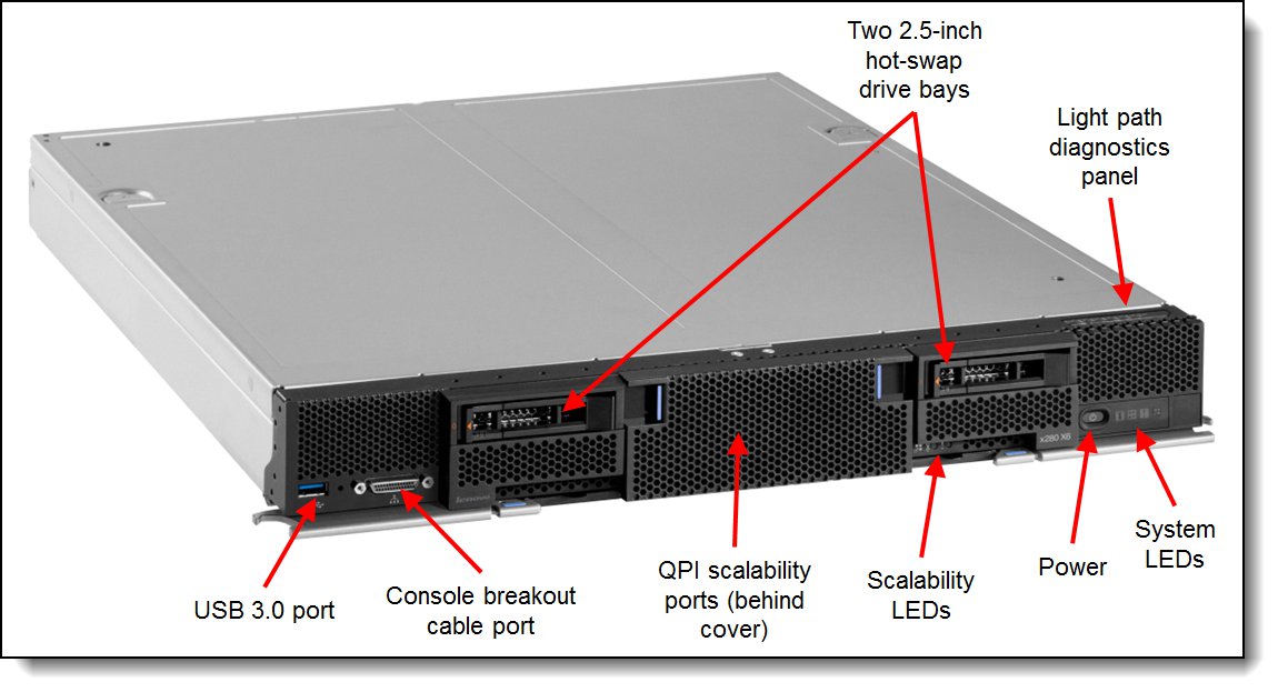
Figure 2. Front view of the Flex System X6 Compute Node
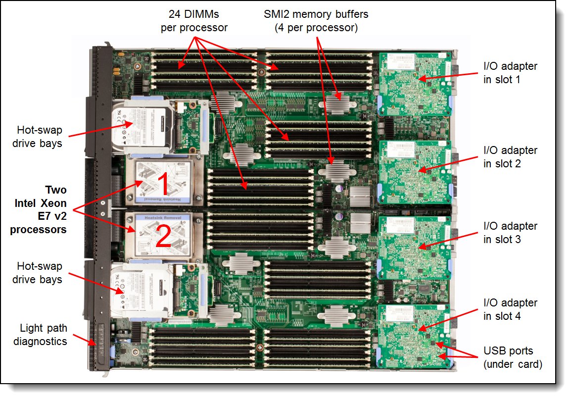
Figure 3. Inside view of the Flex System X6 Compute Node
The following figure shows how four x880 Compute Nodes can be connected together to form a single 8-socket complex. Note this is for illustrative purposes only; in a production environment, you first install the compute nodes in the chassis and then attach the scalability connector to all four nodes.
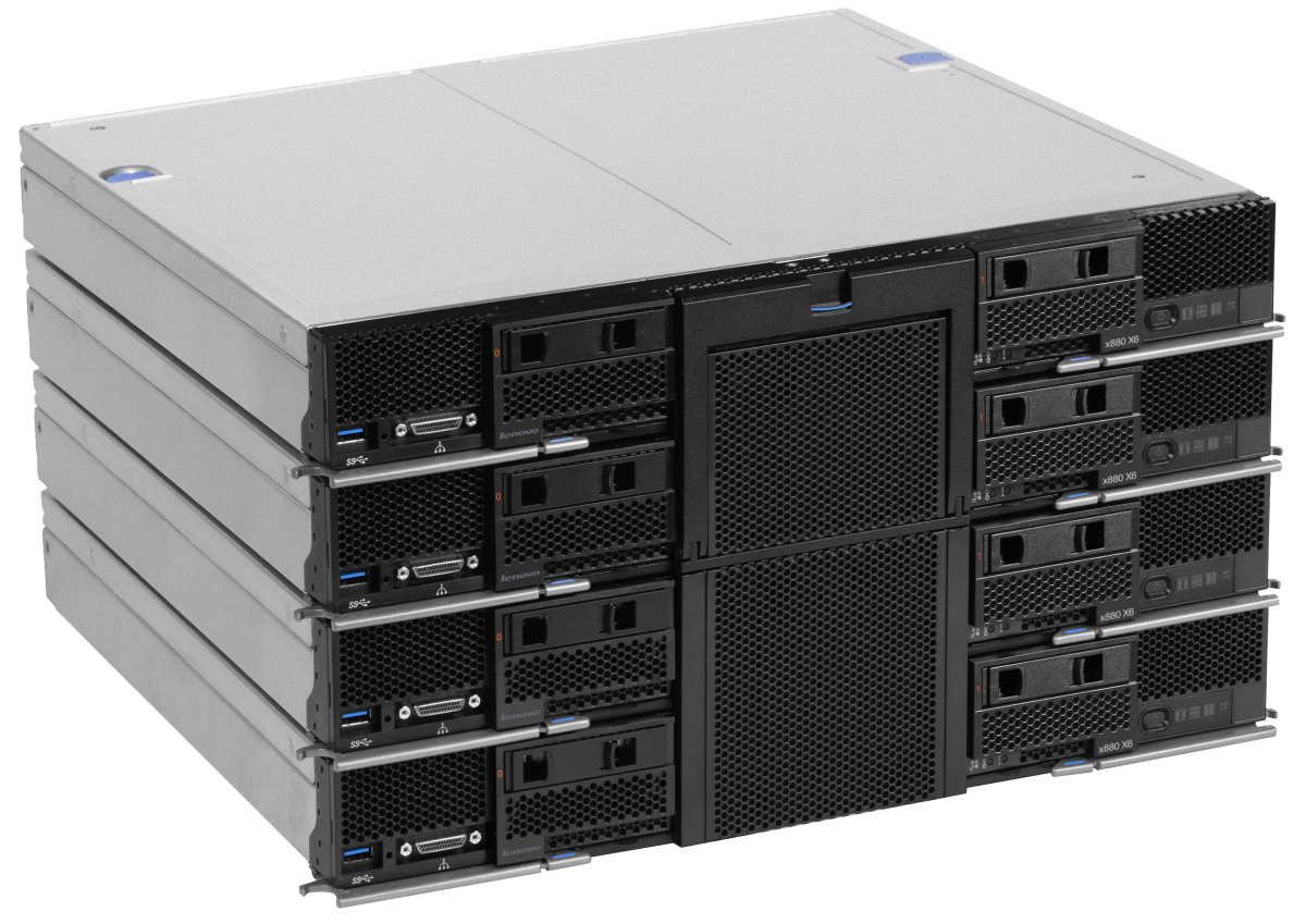
Figure 4. Four x880 X6 Compute Nodes in an 8-socket complex
Standard specifications
The following table lists the standard specifications.
| Components | Specification (per node except where noted) |
|---|---|
| Machine type | 7903 |
| Firmware | IBM-signed firmware |
| Form factor | Double-wide compute node. |
| Chassis support | Flex System Enterprise Chassis. |
| Scalability | x880 X6:
|
| Processor | The processor selection determines whether the compute node is an x880 X6, x480 X6, or x280 X6:
|
| Chipset | Intel C602J. |
| Memory | Up to 48 DIMM sockets (24 DIMMs per processor) using Low Profile (LP) DDR3 DIMMs. RDIMMs and LRDIMMs are supported. 1.5 V and low-voltage 1.35 V DIMMs are supported. Support for up to 1600 MHz memory speed, depending on the processor. Four SMI2 channels to memory buffer per processor. Two memory channels per memory buffer. Supports three DIMMs per channel. |
| Memory maximums | With LRDIMMs: Up to 3 TB with 48x 64 GB LRDIMMs and two processors. With RDIMMs: Up to 768 GB with 48x 16 GB RDIMMs and two processors. |
| Memory protection | ECC, Chipkill (for x4-based memory DIMMs), memory mirroring, and memory rank sparing. |
| Memory-channel storage | eXFlash DIMMs not supported. |
| Disk drive bays | Standard: Two 2.5-inch hot-swap SAS/SATA drive bays that support SAS, SATA, and SSD drives. |
| Maximum internal storage | With two 2.5-inch hot-swap drives: Up to 3.6 TB with 1.8 TB 2.5" SAS HDDs, or up to 7.68 TB with 3.84 TB 2.5" SSDs, or up to 2 TB with 1 TB NL SATA drives. Intermix of SAS and SATA HDDs and SSDs is supported. |
| RAID support | RAID 0, 1, 1E, and 10 with integrated ServeRAID M1200e (based on LSI SAS3004), upgradeable to RAID 5 and 50. Two adjacent compute nodes each with two drives can form a 4-drive RAID 10 array. |
| Network interfaces | None standard; optional Ethernet adapters. |
| PCI Expansion slots | Up to four I/O connectors for adapters. Two connectors have PCI Express 3.0 x24 (x16 + x8) interface with support for dual-ASIC adapters (slots 1 and 2), two other connectors have PCI Express 3.0 x8 interface (slots 3 & 4). |
| Ports | External: One USB 3.0. Console breakout cable port that provides local KVM and serial ports (cable comes standard with Flex System chassis; additional cables are optional). Internal: Two internal USB 2.0 for embedded hypervisor. |
| Systems management | UEFI, Integrated Management Module 2 (IMM2) with Renesas SH7757 controller, Predictive Failure Analysis, light path diagnostics panel, automatic server restart, and remote presence. Support for Lenovo XClarity Administrator, IBM Flex System Manager™, IBM Systems Director, and ServerGuide. |
| Security features | Power-on password, administrator's password, and Trusted Platform Module V1.2. |
| Video | Matrox G200eR2 video core with 16 MB video memory that is integrated into the IMM2. Maximum resolution is 1600x1200 at 75 Hz with 16 M colors. |
| Limited warranty | Three-year customer-replaceable unit and onsite limited warranty with 9x5/NBD. |
| Operating systems supported | Microsoft Windows Server, Red Hat Enterprise Linux, SUSE Linux Enterprise Server, VMware ESXi. See the Operating system support section for specifics. |
| Service and support | Optional service upgrades are available through Lenovo Services offerings: Four-hour or 2-hour response time, 24-hour or 8-hour fix time, 1-year or 2-year warranty extension, and remote technical support for Lenvoo hardware and selected Lenovo and OEM software. |
| Dimensions | Width: 435 mm (17.14 in.), height 55 mm (2.19 in.), depth 500 mm (19.7 in.) |
| Weight | Maximum weight: 12.25 kg (27 lbs). |
The X6 Compute Nodes are shipped with the following items:
- Statement of Limited Warranty
- Important Notices
- Documentation CD that contains the Installation and Service Guide
Standard models
The following table lists the standard models. Currently, the x480 X6 is available as a standard model. The x280 X6 and x880 X6 are available configure-to-order only.
Table 2. Standard models
| Model | Intel Processor** (2 maximum) |
Memory | RAID | Disk bays (used/max) |
10GbE Embedded |
I/O slots (used/max) |
| x280 X6 (2-socket only) | ||||||
| 7903-A2x | 2x E7-2850 v2 12C 2.3GHz 24MB 1600MHz 105W |
2 x 16GB 1600 MHz |
LSI 3004 | 2.5” HS (0 / 2) Open bay |
No | 0 / 4 |
| 7903-B2x | 2x 7-2880 v2 15C 2.5GHz 37.5MB 1600MHz 130W |
2 x 16GB 1600 MHz |
LSI 3004 | 2.5” HS (0 / 2) Open bay |
No | 0 / 4 |
| 7903-C2x | 2x E7-2890 v2 15C 2.8GHz 37.5MB 1600MHz 155W |
2 x 16GB 1600 MHz |
LSI 3004 | 2.5” HS (0 / 2) Open bay |
No | 0 / 4 |
| x480 X6 (2-socket, can scale up to 4-socket) | ||||||
| 7903-D2x | 2x E7-4809 v2 6C 1.9GHz 12MB 1333MHz 105W |
2 x 16GB (1333 MHz)‡ |
LSI 3004 | 2.5” HS (0 / 2) Open bay |
No | 0 / 4 |
| 7903-F2x | 2x E7-4820 v2 8C 2.0GHz 16MB 1600MHz 105W |
2 x 16GB 1600 MHz |
LSI 3004 | 2.5” HS (0 / 2) Open bay |
No | 0 / 4 |
| 7903-G2x | 2x E7-4830 v2 10C 2.2GHz 20MB 1600MHz 105W |
2 x 16GB 1600 MHz |
LSI 3004 | 2.5” HS (0 / 2) Open bay |
No | 0 / 4 |
| 7903-H2x | 2x E7-4850 v2 12C 2.3GHz 24MB 1600MHz 105W |
2 x 16GB 1600 MHz |
LSI 3004 | 2.5” HS (0 / 2) Open bay |
No | 0 / 4 |
| 7903-J2x | 2x E7-4870 v2 15C 2.3GHz 30MB 1600MHz 130W |
2 x 16GB 1600 MHz |
LSI 3004 | 2.5” HS (0 / 2) Open bay |
No | 0 / 4 |
| 7903-L2x | 2x E7-4880 v2 15C 2.5GHz 37.5MB 1600MHz 130W |
2 x 16GB 1600 MHz |
LSI 3004 | 2.5” HS (0 / 2) Open bay |
No | 0 / 4 |
| 7903-M2x | 2x E7-4890 v2 15C 2.8GHz 37.5MB 1600MHz 155W |
2 x 16GB 1600 MHz |
LSI 3004 | 2.5” HS (0 / 2) Open bay |
No | 0 / 4 |
| x880 X66 (2-socket, can scale up to 4-socket or 8-socket) | ||||||
| 7903-N2x | 2x E7-8850 v2 12C 2.3GHz 24MB 1600MHz 105W |
2 x 16GB 1600 MHz |
LSI 3004 | 2.5” HS (0 / 2) Open bay |
No | 0 / 4 |
| 7903-Q2x | 2x E7-8880 v2 15C 2.5GHz 37.5MB 1600MHz 130W |
2 x 16GB 1600 MHz |
LSI 3004 | 2.5” HS (0 / 2) Open bay |
No | 0 / 4 |
| 7903-R2x | 2x E7-8890 v2 15C 2.8GHz 37.5MB 1600MHz 155W |
2 x 16GB 1600 MHz |
LSI 3004 | 2.5” HS (0 / 2) Open bay |
No | 0 / 4 |
** Processor detail: Processor quantity and model, cores, core speed, L3 cache, memory speed, and power consumption.
‡ For models D2x, the standard DIMM is rated at 1600 MHz, but operates at 1333 MHz to match the processor memory speed.
Chassis support
The X6 Compute Nodes are supported in the Flex System Enterprise Chassis as listed in the following table:
Table 3. Chassis support
| Compute node |
Enterprise Chassis with CMM 68Y7030 |
Enterprise Chassis with CMM2 00FJ669 |
Carrier-Grade Chassis |
| x280 X6 (7903) | Yes | Yes | No |
| x480 X6 (7903) | Yes | Yes | No |
| x880 X6 (7903) | Yes | Yes | No |
Up to seven X6 compute nodes can be installed in the chassis in 10U of rack space. The number of scaled systems that can be installed is as follows:
- Two-socket systems: Up to seven systems in an Enterprise Chassis
- Four-socket systems: Up to three systems in an Enterprise Chassis
- Eight-socket systems: One system in an Enterprise Chassis
It might also be possible to populate the remaining bays within the chassis with other standard or double-wide nodes. The actual number of servers that can be installed in a chassis also depends on these factors:
- The TDP power rating for the processors that are installed in the server
- The number of power supplies that are installed
- The capacity of the power supplies that are installed (2100 W or 2500 W)
- The power redundancy policy that is used (N+1 or N+N)
The following table provides guidelines about what number of X6 Compute Nodes can be installed. For more information, use the Power Configurator, found at the following website:
http://ibm.com/systems/bladecenter/resources/powerconfig.html
In the table:
- Green = No restriction to the number of X6 Compute Nodes that are installable.
- Yellow = Some bays must be left empty in the chassis.
Table 4. Maximum number of X6 Compute Nodes that are installable based on the power supplies that are installed and the power redundancy policy that is used
| TDP rating |
2100 W power supplies installed
|
2500 W power supplies installed
|
||||||
| N+1, N=5 6 power supplies |
N+1, N=4 5 power supplies |
N+1, N=3 4 power supplies |
N+N, N=3 6 power supplies |
N+1, N=5 6 power supplies |
N+1, N=4 5 power supplies |
N+1, N=3 4 power supplies |
N+N, N=3 6 power supplies |
|
| x280, x480, or x880 X6 with 2 sockets | ||||||||
| 105 W | 7 | 7 | 6 | 6 | 7 | 7 | 7 | 7 |
| 130 W | 7 | 7 | 5 | 6 | 7 | 7 | 7 | 7 |
| 155 W | 7 | 7 | 5 | 5 | 7 | 7 | 7 | 7 |
| x480 or x880 X6 with 4 sockets | ||||||||
| 105 W | 3 | 3 | 3 | 3 | 3 | 3 | 3 | 3 |
| 130 W | 3 | 3 | 3 | 3 | 3 | 3 | 3 | 3 |
| 155 W | 3 | 3 | 2 | 3 | 3 | 3 | 3 | 3 |
| x880 X6 with 8 sockets | ||||||||
| 105 W | 1 | 1 | 1 | 1 | 1 | 1 | 1 | 1 |
| 130 W | 1 | 1 | 1 | 1 | 1 | 1 | 1 | 1 |
| 155 W | 1 | 1 | 1 | 1 | 1 | 1 | 1 | 1 |
Scalability
The X6 compute nodes can scale to a 4-socket or 8-socket complex depending on the processor that is installed into the node:
- An x880 X6 node with Intel Xeon E7-8800 v2 family processors can scale up to an 8-socket configuration, and supports 2-socket, 4-socket, and 8-socket configurations. All the processors in these 2-socket, 4-socket, and 8-socket configurations must be identical.
- An x480 X6 node with Intel Xeon E7-4800 v2 family processors can scale up to a 4-socket configuration, and supports 2-socket and 4-socket configurations. All the processors in these 2-socket and 4-socket configurations must be identical.
- An x280 X6 node with Intel Xeon E7-2800 v2 family processors supports only 2-socket configurations. The processors in 2-socket configurations must be identical.
The scaled X6 compute nodes are connected together through a front interconnect system. The interconnection has a QPI bus plus the sideband signals that are needed for correct operation.
There are two scalability connector assemblies for X6 nodes, as shown in the following table.
Table 5. Scalability options for X6 compute nodes
| Part number |
Feature code | Description |
| 00Y3871 | A4D8 | Flex System x880 X6 4-Socket Scalability Connector (used to connect two x480 or x880 Compute Nodes together) |
| 00Y3874 | A4D9 | Flex System x880 X6 8-Socket Scalability Connector (used to connect four x880 Compute Nodes together) |
The following figure shows the Flex System x880 X6 4-Socket Scalability Connector and how it is used to connect two X6 servers together (x880 or x480).
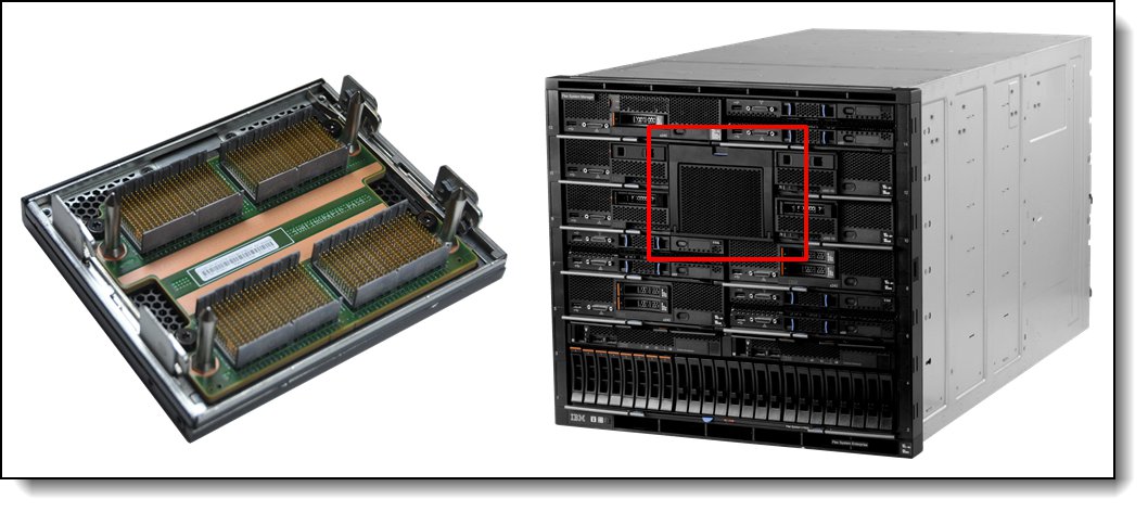
Figure 5. Flex System x880 X6 4-Socket Scalability Connector
Processor options
The X6 compute nodes support the processor options that are listed in the following table. The server supports two Intel Xeon E7-2800 v2, E7-4800 v2, or E7-8800 v2 processors depending on model. The table also shows which server models have each processor standard. If no corresponding model for a particular processor is listed, the processor is available only through the configure-to-order (CTO) process.
No part numbers: All Flex System X6 Compute Nodes have two processors as a standard. There is no option part number for processors, only feature codes.
Table 6. Processor options
| Feature code* | Intel Xeon processor description | Memory bus speed (RAS / Performance)† |
Models where used |
| Flex System x280 X6 Compute Node | |||
| A4E0 / A4DF | Xeon E7-2850 v2 12C 2.3GHz 24MB 1600MHz 105W | 1600 / 1066 MHz | A2x |
| A4E1 / A4DG | Xeon E7-2870 v2 15C 2.3GHz 30MB 1600MHz 130W | 1600 / 1333 MHz | - |
| A4E2 / A4DE | Xeon E7-2880 v2 15C 2.5GHz 37.5MB 1600MHz 130W | 1600 / 1333 MHz | B2x |
| A4E3 / A4DH | Xeon E7-2890 v2 15C 2.8GHz 37.5MB 1600MHz 155W | 1600 / 1333 MHz | C2x |
| Flex System x480 X6 Compute Node | |||
| A4E4 / A4DJ | Xeon E7-4809 v2 6C 1.9GHz 12MB 1333MHz 105W | 1333 / 1066 MHz | D2x |
| A4E5 / A4DK | Xeon E7-4820 v2 8C 2.0GHz 16MB 1600MHz 105W | 1600 / 1066 MHz | F2x |
| A4E6 / A4DL | Xeon E7-4830 v2 10C 2.2GHz 20MB 1600MHz 105W | 1600 / 1066 MHz | G2x |
| A4E7 / A4DM | XeonE7-4850 v2 12C 2.3GHz 24MB 1600MHz 105W | 1600 / 1066 MHz | H2x |
| A4E8 / A4DN | Xeon E7-4860 v2 12C 2.6GHz 30MB 1600MHz 130W | 1600 / 1333 MHz | - |
| A4E9 / A4DP | Xeon E7-4870 v2 15C 2.3GHz 30MB 1600MHz 130W | 1600 / 1333 MHz | J2x |
| A4EA / A4DQ | Xeon E7-4880 v2 15C 2.5GHz 37.5MB 1600MHz 130W | 1600 / 1333 MHz | L2x |
| A4EB / A4DR | Xeon E7-4890 v2 15C 2.8GHz 37.5MB 1600MHz 155W | 1600 / 1333 MHz | M2x |
| Flex System x880 X6 Compute Node | |||
| A4EC / A4DS | Xeon E7-8850 v2 12C 2.3GHz 24MB 1600MHz 105W | 1600 / 1066 MHz | N2x |
| A4EE / A4DU | Xeon E7-8870 v2 15C 2.3GHz 30MB 1600MHz 130W | 1600 / 1333 MHz | - |
| A4EG / A4DW | Xeon E7-8880 v2 15C 2.5GHz 37.5MB 1600MHz 130W | 1600 / 1333 MHz | Q2x |
| A4EH / A4DX | Xeon E7-8890 v2 15C 2.8GHz 37.5MB 1600MHz 155W | 1600 / 1333 MHz | R2x |
| A4EK / A4DZ | Xeon E7-8893 v2 6C 3.4GHz 37.5MB 1600MHz 155W | 1600 / 1333 MHz | - |
| A4EJ / A4DY | Xeon E7-8891 v2 10C 3.2GHz 37.5MB 1600MHz 155W | 1600 / 1333 MHz | - |
| A4ED / A4DT | Xeon E7-8857L v2 12C 3.0GHz 30MB 1600MHz 130W | 1600 / 1333 MHz | - |
| A4EF / A4DV | Xeon E7-8880L v2 15C 2.2GHz 37.5MB 1600MHz 105W | 1600 / 1333 MHz | - |
* The first feature code is for CPU 1 and the second feature code is for CPU 2.
† The processors support two memory modes: RAS mode (also known as lockstep mode) and Performance mode (also known as independent mode). In Performance mode, the SMI2 link operates at twice the memory bus speed that is shown.
Memory options
Lenovo DDR3 memory is compatibility tested and tuned for optimal performance and throughput. Lenovo memory specifications are integrated into the light path diagnostic tests for immediate system performance feedback and optimum system uptime. From a service and support standpoint, Lenovo memory automatically assumes the system warranty.
The X6 Compute Nodes support DDR3 memory operating at speeds up to 1600 MHz with 24 DIMMs per processor:
- A 2-socket configuration supports up to 48 DIMMs.
- A 4-socket scaled configuration supports up to 96 DIMMs.
- An 8-socket configuration supports up to 192 DIMMs.
The following table lists the memory options that are available for X6 Compute Nodes.
Table 7. Memory options
| Part number | Feature code | Description | Maximum supported |
Models where used |
| RDIMMs | ||||
| 00D5024 | A3QE | 4GB (1x4GB, 1Rx4, 1.35V) PC3L-12800 CL11 ECC DDR3 1600MHz LP RDIMM |
48 (24 per CPU) | - |
| 00D5036 | A3QH | 8GB (1x8GB, 1Rx4, 1.35V) PC3L-12800 CL11 ECC DDR3 1600MHz LP RDIMM |
48 (24 per CPU) | - |
| 46W0672 | A3QM | 16GB (1x16GB, 2Rx4, 1.35V) PC3L-12800 CL11 ECC DDR3 1600MHz LP RDIMM |
48 (24 per CPU) | All models |
| LRDIMMs | ||||
| 46W0676 | A3SR | 32GB (1x32GB, 4Rx4, 1.35V) PC3L-12800 CL11 ECC DDR3 1600MHz LP LRDIMM |
48 (24 per CPU) | - |
| 46W0741 | A451 | 64GB (1x64GB, 8Rx4, 1.35V) PC3-10600 DDR3 1333MHz LP LRDIMM |
48 (24 per CPU) | - |
Each processor has four memory channels to memory buffers that are implemented using Scalable Memory Interface generation 2 (SMI2) chips. Each memory buffer has two memory channels and implements three DIMMs per channel.
The following rules apply when selecting the memory configuration:
- The X6 node supports RDIMMs and LRDIMMs.
- LR-DIMMs and RDIMMs cannot be mixed within a single compute node or a scaled complex.
- Mixing 1.5 V and 1.35 V DIMMs in the same server is supported. In such a case, all DIMMs operate at 1.5 V.
- The processors support two memory modes: Performance mode and RAS (or lockstep) mode. In RAS (lockstep) mode, DIMMs must be installed in a pair, and the SMI link operates at the speed of the memory bus.
- When RDIMMs are installed, the maximum number of ranks that are supported per channel is eight. With LRDIMMs, the rank count per channel can be 32 (LRDIMM ranks are only 25% of the electrical load of an RDIMM rank).
- All DIMMs in all processor memory channels operate at the same speed, which is determined as the lowest value of the following components:
- The memory mode used: Performance (independent) mode or RAS (lockstep) mode.
- Memory speed that is supported by a specific processor.
- Lowest of maximum operating speeds for selected memory configuration, depending on the rated speed, operating voltage, and quantity of DIMMs per channel, as shown under the “Maximum operating speed” section in the following table.
The following table shows the characteristics of the supported DIMMs. Tables cells that are highlighted with a gray background indicate that the server supports higher memory frequencies or larger memory capacity (or both) than the Intel processor specification defines.
Memory speed: In performance mode, memory channels operate independently, and the SMI2 link operates at twice the DDR3 speed. In RAS mode, two channels operate synchronously, and the SMI2 link operates at the DDR3 speed.
Table 8. Maximum memory speeds
| DIMM specification |
RDIMM
|
LRDIMM
|
||||||
| Rank | Single rank | Dual rank | Quad rank | 8-rank | ||||
| Part numbers | 00D5024 (4GB) 00D5036 (8GB) |
46W0672 (16GB) | 46W0676 (32GB) | 46W0741 (64GB) | ||||
| Rated speed | 1600 MHz | 1600 MHz | 1600 MHz | 1333 MHz | ||||
| Rated voltage | 1.35 V | 1.35 V | 1.35 V | 1.35 V | ||||
| Operating voltage | 1.35 V | 1.5 V | 1.35 V | 1.5 V | 1.35 V | 1.5 V | 1.35 V | 1.5 V |
| Max qty supported* | 96 | 96 | 96 | 96 | 96 | 96 | 96 | 96 |
| Max DIMM capacity | 8 GB | 8 GB | 16 GB | 16 GB | 32 GB | 32 GB | 64 GB | 64 GB |
| Max memory capacity | 0.75 TB | 0.75 TB | 1.5 TB | 1.5 TB | 3 TB | 3 TB | 6 TB | 6 TB |
| Maximum operating speed - Performance mode (2:1 mode - SMI2 link operates at twice the DDR3 speed that is shown) | ||||||||
| 1 DIMM per channel | 1333 MHz | 1333 MHz | 1333 MHz | 1333 MHz | 1333 MHz | 1333 MHz | 1333 MHz | 1333 MHz |
| 2 DIMMs per channel | 1333 MHz | 1333 MHz | 1333 MHz | 1333 MHz | 1333 MHz | 1333 MHz | 1333 MHz | 1333 MHz |
| 3 DIMMs per channel | 1066 MHz | 1333 MHz | 1066 MHz | 1333 MHz | 1333 MHz | 1333 MHz | 1333 MHz | 1333 MHz |
| Maximum operating speed - RAS mode (1:1 mode - SMI2 link operates at the DDR3 speed that is shown) | ||||||||
| 1 DIMM per channel | 1333 MHz | 1600 MHz | 1333 MHz | 1600 MHz | 1333 MHz | 1600 MHz | 1333 MHz | 1333 MHz |
| 2 DIMMs per channel | 1333 MHz | 1600 MHz | 1333 MHz | 1600 MHz | 1333 MHz | 1600 MHz | 1333 MHz | 1333 MHz |
| 3 DIMMs per channel | 1066 MHz | 1333 MHz | 1066 MHz | 1333 MHz | 1333 MHz | 1333 MHz | 1333 MHz | 1333 MHz |
* Maximum quantity that is supported is shown for all the processors that are installed.
The following memory protection technologies are supported:
- ECC
- Chipkill (for x4-based memory DIMMs)
- Redundant bit steering (Double Device Data Correction)
- Memory mirroring
- Memory rank sparing
Chipkill and Redundant Bit Steering are supported in RAS mode. Chipkill is supported in Performance mode.
If memory mirroring is used, DIMMs must be installed in pairs for Performance mode (minimum of one pair per each processor) and quads for RAS mode. DIMMs in the pair/quad must be identical in type and size.
If memory rank sparing is used, then a minimum of two single-rank or dual-rank DIMMs must be installed per populated channel (the DIMMs do not need being identical). In rank sparing mode, one rank of a DIMM in each populated channel is reserved as spare memory. The size of a rank varies depending on the DIMMs that are installed.
Internal storage
The X6 compute node has two 2.5-inch front-accessible hot-swap drive bays that are accessible from the front of the server. These bays are connected to the integrated ServeRAID M1210e controller.
The ServeRAID M1210e controller includes the following features:
- Based on the LSI SAS 3004 12 Gbps SAS/SATA RAID-on-Chip (ROC) controller
- Four-port controller with 12 Gbps throughput per port
- PCIe x4 Gen 2 host interface
- Supports RAID levels 0, 1, 10, and 1E; optionally supports RAID 5 and RAID 50.
RAID 5 and RAID 50 are supported through a Features on Demand upgrade, as shown in the following table. For 4-socket and 8-socket complexes, one FoD upgrade is required for each SAS controller on which you want to enable RAID 5.
Table 9. ServeRAID M1210e upgrades
| Part number | Feature code |
Name and description | Maximum supported |
| 00AE930 | A5H5 | ServeRAID M1200 Zero Cache/RAID 5 Upgrade (FOD) | 1 |
Supported drives are listed in the "Internal drive options" section.
Note: The X6 Compute Node, machine type 7903, does not support 1.8-inch drives nor the ServeRAID M5115.
Internal drive options
The 2.5-inch drive bays support SAS or SATA HDDs or SATA SSDs. The following table lists the supported 2.5-inch drive options.
| Part number |
Feature code |
Description | Maximum supported |
|---|---|---|---|
| 2.5-inch 6Gb 10K SAS hard disk drives | |||
| 00AJ146 | A4TP | 1.2TB 10K 6Gbps SAS 2.5'' G3HS HDD | 2 |
| 00AJ071 | A4TN | 900GB 10K 6Gbps SAS 2.5" SFF G3HS HDD | 2 |
| 00AJ091 | A4TM | 600GB 10K 6Gbps SAS 2.5" SFF G3HS HDD | 2 |
| 00AJ096 | A4TL | 300GB 10K 6Gbps SAS 2.5" SFF G3HS HDD | 2 |
| 2.5-inch 6Gb 10K and 15K SAS self-encrypting drives (SEDs) | |||
| 00AJ151 | A4U1 | 1.2TB 10K 6Gbps SAS 2.5'' G3HS SED | 2 |
| 00AJ076 | A4U0 | 900GB 10K 6Gbps SAS 2.5" SFF G3HS SED | 2 |
| 00AJ101 | A4TZ | 600GB 10K 6Gbps SAS 2.5" SFF G3HS SED | 2 |
| 00AJ106 | A4TY | 300GB 10K 6Gbps SAS 2.5" SFF G3HS SED | 2 |
| 00AJ116 | A4U2 | 146GB 15K 6Gbps SAS 2.5" G3HS SED | 2 |
| 2.5-inch 6Gb 15K SAS hard disk drives | |||
| 00AJ126 | A4TS | 600GB 15K 6Gbps SAS 2.5" G3HS HDD | 2 |
| 00AJ081 | A4TR | 300GB 15K 6Gbps SAS 2.5" G3HS HDD | 2 |
| 00AJ111 | A4TQ | 146GB 15K 6Gbps SAS 2.5" G3HS HDD | 2 |
| 2.5-inch 6Gb NL SATA drives | |||
| 00AJ141 | A4TX | 1TB 7.2K 6Gbps NL SATA 2.5" G3HS HDD | 2 |
| 00AJ136 | A4TW | 500GB 7.2K 6Gbps NL SATA 2.5" G3HS HDD | 2 |
| 00AJ131 | A4TV | 250GB 7.2K 6Gbps NL SATA 2.5" G3HS HDD | 2 |
| 2.5-inch 6Gb NL SAS drives | |||
| 00AJ086 | A4TU | 1TB 7.2K 6Gbps NL SAS 2.5'' G3HS HDD | 2 |
| 00AJ121 | A4TT | 500GB 7.2K 6Gbps NL SAS 2.5" G3HS HDD | 2 |
| 2.5-inch 12Gb SAS 15K hot-swap HDDs | |||
| 00NA221 | ASBB | 300GB 15K 12Gbps SAS 2.5" G3HS 512e HDD | 2 |
| 00NA231 | ASBD | 600GB 15K 12Gbps SAS 2.5" G3HS 512e HDD | 2 |
| 2.5-inch 12Gb SAS 10K hot-swap HDDs | |||
| 00NA241 | ASBF | 600GB 10K 12Gbps SAS 2.5" G3HS 512e HDD | 2 |
| 00NA251 | ASBH | 900GB 10K 12Gbps SAS 2.5" G3HS 512e HDD | 2 |
| 00NA261 | ASBK | 1.2TB 10K 12Gbps SAS 2.5" G3HS 512e HDD | 2 |
| 00NA271 | ASBM | 1.8TB 10K 12Gbps SAS 2.5" G3HS 512e HDD | 2 |
| 2.5-inch 12Gb SAS 15K hot-swap SEDs | |||
| 00NA281 | ASBP | 300GB 15K 12Gbps SAS 2.5" G3HS 512e SED | 2 |
| 00NA286 | ASBQ | 600GB 15K 12Gbps SAS 2.5" G3HS 512e SED | 2 |
| 2.5-inch 12Gb SAS 10K hot-swap SEDs | |||
| 00NA291 | ASBR | 600GB 10K 12Gbps SAS 2.5" G3HS 512e SED | 2 |
| 00NA296 | ASBS | 900GB 10K 12Gbps SAS 2.5" G3HS 512e SED | 2 |
| 00NA301 | ASBT | 1.2TB 10K 12Gbps SAS 2.5'' G3HS 512e SED | 2 |
| 00NA306 | ASBU | 1.8TB 10K 12Gbps SAS 2.5'' G3HS 512e SED | 2 |
| 2.5-inch 12Gb SAS 15K hot-swap hybrid HDDs | |||
| 00NA311 | ASBV | 300GB 15K 12Gbps SAS 2.5" G3HS 512e Hybrid | 2 |
| 00NA321 | ASBX | 600GB 15K 12Gbps SAS 2.5" G3HS 512e Hybrid | 2 |
| 2.5-inch 6Gb Enterprise Capacity SSDs | |||
| 00NA671 | ASW6 | 3.84 TB 6 Gb SAS Enterprise Capacity G3HS MLC SSD | 2 |
| 2.5-inch 6Gb Enterprise SSDs | |||
| 00AJ222 | A4UD | 1.6TB SAS 2.5" MLC G3HS Enterprise SSD | 2 |
| 00AJ217 | A4UC | 800GB SAS 2.5" MLC G3HS Enterprise SSD | 2 |
| 00AJ212 | A4UB | 400GB SAS 2.5" MLC G3HS Enterprise SSD | 2 |
| 00AJ207 | A4UA | 200GB SAS 2.5" MLC G3HS Enterprise SSD | 2 |
| 00AJ166 | A4U5 | S3700 800GB SATA 2.5" MLC G3HS Enterprise SSD | 2 |
| 00AJ161 | A4U4 | S3700 400GB SATA 2.5" MLC G3HS Enterprise SSD | 2 |
| 00AJ156 | A4U3 | S3700 200GB SATA 2.5" MLC G3HS Enterprise SSD | 2 |
| 2.5-inch 6Gb Enterprise Value SSDs | |||
| 00AJ395 | A577 | 120GB SATA 2.5" MLC G3HS Enterprise Value SSD | 2 |
| 00AJ400 | A578 | 240GB SATA 2.5" MLC G3HS Enterprise Value SSD | 2 |
| 00AJ405 | A579 | 480GB SATA 2.5" MLC G3HS Enterprise Value SSD | 2 |
| 00AJ410 | A57A | 800GB SATA 2.5" MLC G3HS Enterprise Value SSD | 2 |
| 00FN278 | A5U6 | S3500 1.6TB SATA 2.5" MLC G3HS Enterprise Value SSD | 1 |
| 2.5-inch 12Gb SAS Enterprise SSDs | |||
| 00FN379 | AS7C | 200GB 12G SAS 2.5" MLC G3HS Enterprise SSD | 2 |
| 00FN389 | AS7E | 400GB 12G SAS 2.5" MLC G3HS Enterprise SSD | 2 |
| 00FN399 | AS7G | 800GB 12G SAS 2.5" MLC G3HS Enterprise SSD | 2 |
| 00FN409 | AS7J | 1.6TB 12G SAS 2.5" MLC G3HS Enterprise SSD | 2 |
| 2.5-inch 12Gb SAS self-encrypting (SED) Enterprise SSDs | |||
| 00FN419 | AS7L | 400GB SED 12G SAS 2.5" MLC G3HS Enterprise SSD | 2 |
| 00FN424 | AS7M | 800GB SED 12G SAS 2.5" MLC G3HS Enterprise SSD | 2 |
Internal tape drives
The server does not support an internal tape drive. However, it can be attached to external tape drives by using Fibre Channel connectivity.
Optical drives
The server does not support an internal optical drive option, however, you can connect an external USB optical drive. See http://support.lenovo.com/en/documents/pd011281 for information about available external optical drives from Lenovo. Alternatively, use the remote media feature of the IMMv2 and the Chassis Management Module.
Note: The USB port on the compute node supplies up to 0.5 A at 5 V. For devices that require more power, an additional power source is required.
I/O expansion options
The X6 compute node has four I/O expansion connectors for attaching I/O adapters, as shown in the following figure. Installing I/O adapters allows the server to connect to switch modules in the Flex System Enterprise Chassis. The following figure shows the location of the four I/O expansion slots.
Note: Slots 3 and 4 support only a subset of the adapters that are supported in slots 1 and 2. Slots 3 and 4 do not support dual-ASIC adapters because of the PCIe lanes that are routed to slots 3 and 4. For specifics, see the "Network adapters" section.
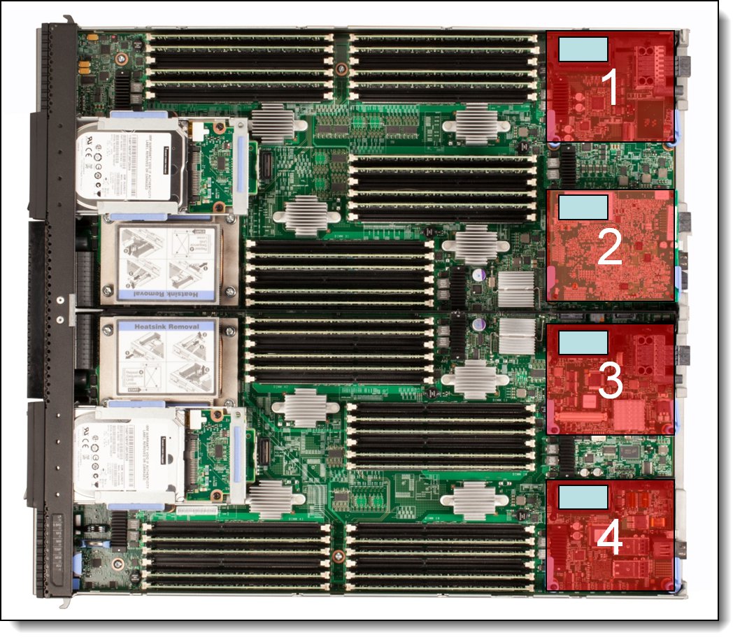
Figure 6. Location of the I/O adapter slots in the X6 Compute Node
A compatible switch or pass-through module must be installed in the corresponding I/O bays in the chassis, as indicated in the following table. Installing two switches means that all the ports of the adapter are enabled, which improves performance and network availability.
Table 11. Adapter to I/O bay correspondence
| I/O adapter slot in the server |
Port on the adapter | Corresponding I/O module bay in the chassis |
| Slot 1 | Port 1 | Module bay 1 |
| Port 2 | Module bay 2 | |
| Port 3 (for 4 & 8-port cards) | Module bay 1 | |
| Port 4 (for 4 & 8-port cards) | Module bay 2 | |
| Port 5 (for 8-port cards) | Module bay 1 | |
| Port 6 (for 8-port cards) | Module bay 2 | |
| Port 7 (for 8-port cards) | Module bay 1 | |
| Port 8 (for 8-port cards) | Module bay 2 | |
| Slot 2 | Port 1 | Module bay 3 |
| Port 2 | Module bay 4 | |
| Port 3 (for 4 & 8-port cards) | Module bay 3 | |
| Port 4 (for 4 & 8-port cards) | Module bay 4 | |
| Port 5 (for 8-port cards) | Module bay 3 | |
| Port 6 (for 8-port cards) | Module bay 4 | |
| Port 7 (for 8-port cards) | Module bay 3 | |
| Port 8 (for 8-port cards) | Module bay 4 | |
| Slot 3 (Dual-ASIC adapters are not supported.) |
Port 1 | Module bay 1 |
| Port 2 | Module bay 2 | |
| Slot 4 (Dual-ASIC adapters are not supported.) |
Port 1 | Module bay 3 |
| Port 2 | Module bay 4 |
For a list of supported switches, see the Flex System Interoperability Guide, available from:
http://lenovopress.com/fsig
The following figure shows the location of the switch bays in the Flex System Enterprise Chassis.
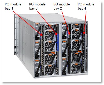
Figure 7. Location of the switch bays in the Flex System Enterprise Chassis
The following figure shows how 2-port adapters are connected to switches that are installed in the chassis.
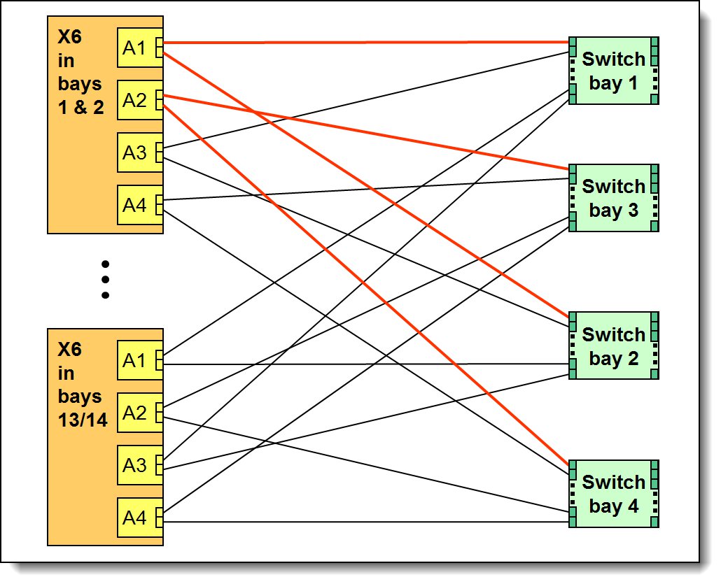
Figure 8. Logical layout of the interconnects between I/O adapters and I/O modules
Network adapters
An Ethernet adapter must be installed in slot 1 to provide network connectivity between the server and the chassis midplane and ultimately to the network switches.
The following table lists the supported network adapters and upgrades and the slots they are each supported in. Compatible switches must be installed in the corresponding bays of the chassis.
Note: The following adapters with two ASICs are not supported in slots 3 and 4:
- Flex System CN4054R 10Gb Virtual Fabric Adapter
- Flex System EN2024 4-port 1Gb Ethernet Adapter
Table 12. Network adapters
| Part number | Feature code |
Flex System adapter | Number of ports |
Maximum supported |
Slots supported |
| 40 Gb Ethernet | |||||
| 90Y3482 | A3HK | EN6132 2-port 40Gb Ethernet Adapter | 2 | 4 | 1, 2, 3 4 |
| 10 Gb Ethernet | |||||
| 00Y3306 | A4K2 | CN4054R 10Gb Virtual Fabric Adapter | 4 | 2 | 1, 2* |
| 90Y3558 | A1R0 | CN4054 Virtual Fabric Adapter (SW Upgrade) (FCoE/iSCSI upgrade for 00Y3306; 1 per adapter |
License | 2 | Not applicable |
| 88Y5920 | A4K3 | CN4022 2-port 10Gb Converged Adapter | 2 | 4 | 1, 2, 3, 4 |
| 90Y3466 | A1QY | EN4132 2-port 10Gb Ethernet Adapter | 2 | 4 | 1, 2, 3, 4 |
| 1 Gb Ethernet | |||||
| 49Y7900 | A10Y | EN2024 4-port 1Gb Ethernet Adapter | 4 | 2 | 1, 2* |
| InfiniBand | |||||
| 90Y3454 | A1QZ | IB6132 2-port FDR InfiniBand Adapter | 2 | 2 | 2, 4 |
* Adapters with two ASICs are not supported in slots 3 and 4 because of the available PCIe lanes in those slots
For adapter-to-switch compatibility, see the Flex System Interoperability Guide:
http://lenovopress.com/fsig
For more information, see the list of Lenovo Press Product Guides in the Adapter cards category:
http://lenovopress.com/flexsystem/adapters
Storage host bus adapters
The following table lists the storage host bus adapters (HBAs) that are supported by the compute node.
Note: The following adapter with two ASICs is not supported in slots 3 and 4:
- Flex System FC5054 4-port 16Gb FC adapter
Table 13. Storage adapters
| Part number | Feature code |
Description | Number of ports |
Maximum supported |
Slots supported |
| Fibre Channel | |||||
| 88Y6370 | A1BP | Flex System FC5022 2-port 16Gb FC Adapter | 2 | 2 | 2, 4 |
| 69Y1938 | A1BM | Flex System FC3172 2-port 8Gb FC Adapter | 2 | 2 | 2, 4 |
| 95Y2375 | A2N5 | Flex System FC3052 2-port 8Gb FC Adapter | 2 | 2 | 2, 4 |
| 95Y2386 | A45R | Flex System FC5052 2-port 16Gb FC Adapter | 2 | 2 | 2, 4 |
| 95Y2391 | A45S | Flex System FC5054 4-port 16Gb FC Adapter | 4 | 1 | 2* |
| 69Y1942 | A1BQ | Flex System FC5172 2-port 16Gb FC Adapter | 2 | 2 | 2, 4 |
* Adapters with two ASICs are not supported in slots 3 and 4 because of the available PCIe lanes in those slots.
Power supplies
Server power is derived from the power supplies that are installed in the chassis. There are no server options regarding power supplies.
Integrated virtualization
The X6 compute node supports the ESXi hypervisor on a USB memory key through two internal USB ports (see Figure 3). The supported USB memory keys are listed in the following table.
There are two types of USB keys: preinstalled keys or blank keys. Blank keys allow you to download a customized version of ESXi and load it onto the key. The compute node supports one or two keys installed, but only certain combinations:
Supported combinations:
- One preinstalled key
- One blank key
- One preinstalled key and one blank key
- Two blank keys
Unsupported combinations:
- Two preinstalled keys
Installing two preinstalled keys prevents ESXi from booting, as described at http://kb.vmware.com/kb/1035107. Having two keys that are installed provides a backup boot device. Both devices are listed in the boot menu, which allows you to boot from either device or to set one as a backup in case the first one becomes corrupted.
The supported USB memory keys are listed in the following table.
Table 14. Virtualization options
| Part number | Feature code | Description | Maximum supported |
| 41Y8298 | A2G0 | Blank USB Memory Key for VMware ESXi Downloads | 2 |
| 41Y8300 | A2VC | USB Memory Key for VMware ESXi 5.0 | 1 |
| 41Y8307 | A383 | USB Memory Key for VMware ESXi 5.0 Update 1 | 1 |
| 41Y8311 | A2R3 | USB Memory Key for VMware ESXi 5.1 | 1 |
| 41Y8382 | A4WZ | USB Memory Key for VMware ESXi 5.1 Update 1 | 1 |
| 41Y8385 | A584 | USB Memory Key for VMware ESXi 5.5 | 1 |
Light path diagnostics panel
For quick problem determination when you are physically at the server, the compute node offers a 3-step guided path:
- The Fault LED on the front panel
- The light path diagnostics panel
- LEDs next to key components on the system board
The light path diagnostics panel is visible when you remove the server from the chassis. The panel is at the upper right side of the compute node, as shown in the following figure.
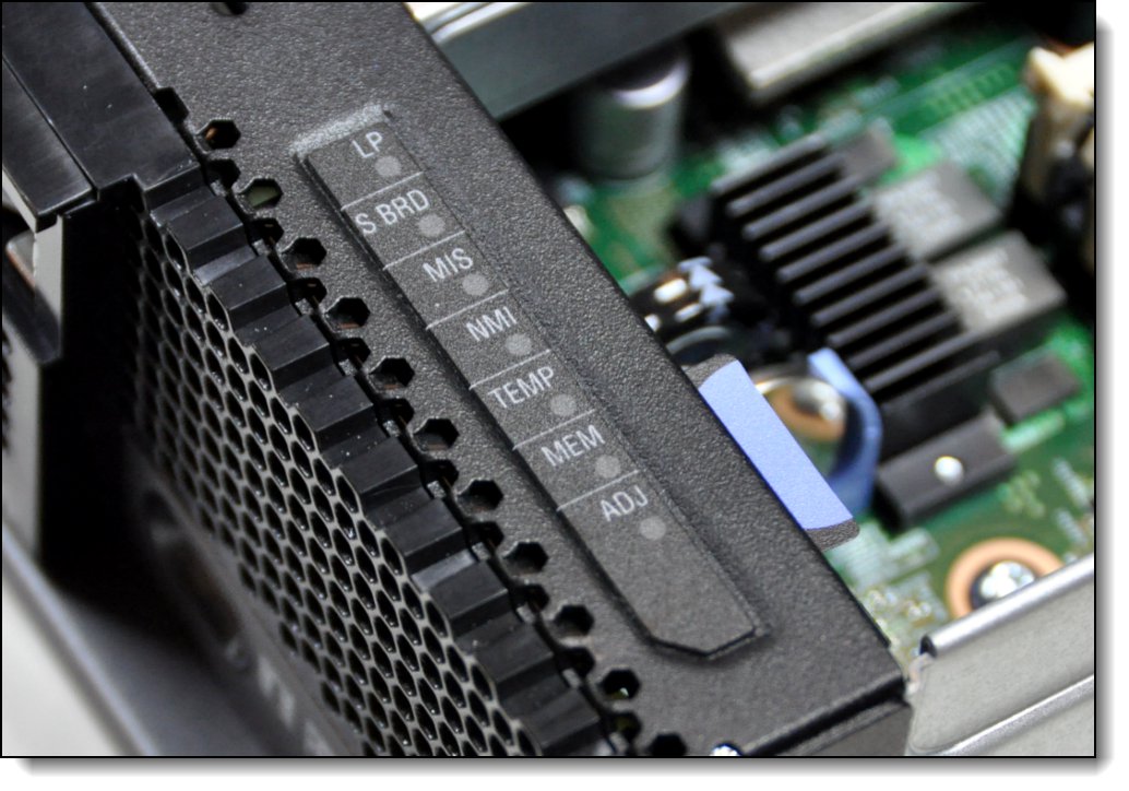
Figure 9. Location of X6 light path diagnostics panel
To illuminate the light path diagnostics LEDs, power off the compute node, slide it out of the chassis, and press the power button. The power button doubles as the light path diagnostics remind button when the server is removed from the chassis. The meanings of the LEDs are listed in the following table.
Table 15. Light path diagnostic panel LEDs
| LED | Meaning |
| LP | The light path diagnostics panel is operational. |
| S BRD | A system board error is detected. |
| MIS | A mismatch has occurred between the processors, DIMMs, or HDDs. |
| NMI | A non-maskable interrupt (NMI) has occurred. |
| TEMP | An over-temperature condition occurred that was critical enough to shut down the server. |
| MEM | A memory fault has occurred. The corresponding DIMM error LEDs on the system board are also lit. |
| ADJ | A fault is detected in the adjacent expansion unit (if installed). |
Remote management
The server contains an Integrated Management Module II (IMM2), which interfaces with the advanced management module in the chassis. The combination of these two components provides advanced service-processor control, monitoring, and an alerting function. If an environmental condition exceeds a threshold or if a system component fails, LEDs on the system board are lit to help you diagnose the problem, the error is recorded in the event log, and you are alerted to the problem. A virtual presence capability comes standard for remote server management.
Remote server management is provided through industry-standard interfaces:
- Intelligent Platform Management Interface (IPMI) Version 2.0
- Simple Network Management Protocol (SNMP) Version 3
- Common Information Model (CIM)
- Web browser
The server also supports virtual media and remote control features, which provide the following functions:
- Remotely viewing video with graphics resolutions up to 1600x1200 at 75 Hz with up to 23 bits per pixel, regardless of the system state
- Remotely accessing the server using the keyboard and mouse from a remote client
- Mapping the CD or DVD drive, diskette drive, and USB flash drive on a remote client, and mapping ISO and diskette image files as virtual drives that are available for use by the server
- Uploading a diskette image to the IMM2 memory and mapping it to the server as a virtual drive
- Capturing blue-screen errors
Operating system support
The server supports the following operating systems:
- Microsoft Windows Server 2008 R2 SP1
- Microsoft Windows Server 2012
- Microsoft Windows Server 2012 R2
- Red Hat Enterprise Linux 6.5 x64
- Red Hat Enterprise Linux 6.6 x64
- Red Hat Enterprise Linux 6.7 x64
- Red Hat Enterprise Linux 6.8 x64
- Red Hat Enterprise Linux 6.10 x64
- Red Hat Enterprise Linux 7.0
- Red Hat Enterprise Linux 7.1
- Red Hat Enterprise Linux 7.2
- Red Hat Enterprise Linux 7.3
- Red Hat Enterprise Linux 7.4
- Red Hat Enterprise Linux 7.5
- Red Hat Enterprise Linux 7.6
- SUSE Linux Enterprise Server 11 Xen x64 SP3
- SUSE Linux Enterprise Server 11 Xen x64 SP4
- SUSE Linux Enterprise Server 11 x64 SP3
- SUSE Linux Enterprise Server 11 x64 SP4
- SUSE Linux Enterprise Server 12
- SUSE Linux Enterprise Server 12 SP1
- SUSE Linux Enterprise Server 12 SP2
- SUSE Linux Enterprise Server 12 SP3
- SUSE Linux Enterprise Server 12 SP4
- SUSE Linux Enterprise Server 12 Xen
- SUSE Linux Enterprise Server 12 Xen SP1
- SUSE Linux Enterprise Server 12 Xen SP2
- SUSE Linux Enterprise Server 12 Xen SP3
- SUSE Linux Enterprise Server 12 Xen SP4
- VMware ESXi 5.1 U2
- VMware ESXi 5.1 U3
- VMware ESXi 5.5 U1
- VMware ESXi 5.5 U2
- VMware ESXi 5.5 U3
- VMware ESXi 6.0
- VMware ESXi 6.0 U1
- VMware ESXi 6.0 U2
- VMware ESXi 6.0 U3
- VMware ESXi 6.5
- VMware ESXi 6.5 U1
- VMware ESXi 6.5 U2
- VMware ESXi 6.5 U3
For a complete list of supported, certified and tested operating systems, plus additional details and links to relevant web sites, see the Operating System Interoperability Guide: https://lenovopress.com/osig#servers=x880-x6-x480-x6-x280-x6-7903
Physical specifications
Dimensions and weight (approximate) for one X6 compute node:
- Width: 435 mm (17.1 in.)
- Height 56 mm (2.1 in.)
- Depth 500 mm (19.7 in.)
- Maximum weight: 12.25 kg (27 lbs)
Supported environment
The Flex System X6 Compute Node complies with ASHRAE Class A3 specifications.
This is the supported operating environment:
Power on:
- Temperature: 5 to 40 °C (41 to 104 °F)
- Humidity, non-condensing: -12 °C dew point (10.4 °F) and 8 - 85% relative humidity
- Maximum dew point: 24 °C (75 °F)
- Maximum altitude: 3048 m (10,000 ft.)
- Maximum rate of temperature change: 5 °C/hr (41 °F/hr)
Power off:
- Temperature: 5 to 45 °C (41 to 113 °F)
- Relative humidity: 8 - 85%
- Maximum dew point: 27 °C (80.6 °F)
Storage (non-operating):
- Temperature: 1 to 60 °C (33.8 to 140 °F)
- Altitude: 3050 m (10,006 ft.)
- Relative humidity: 5 - 80%
- Maximum dew point: 29 °C (84.2°F)
Shipment (non-operating):
- Temperature: -40 to 60 °C (-40 to 140 °F)
- Altitude: 10,700 m (35,105 ft)
- Relative humidity: 5 - 100%
- Maximum dew point: 29 °C (84.2 °F)
Warranty options
The Flex System X6 Compute Node has a three-year warranty with 24x7 standard call center support and 9x5 Next Business Day onsite coverage. Also available are Lenovo Services warranty maintenance upgrades and post-warranty maintenance agreements, with a well-defined scope of services, including service hours, response time, term of service, and service agreement terms and conditions.
Lenovo warranty service upgrade offerings are country-specific. Not all warranty service upgrades are available in every country. For more information about Lenovo warranty service upgrade offerings that are available in your country, visit the Lenovo Services website:
https://www-304.ibm.com/sales/gss/download/spst/servicepac/extProductSelectorWWW.do
The following table explains warranty service definitions in more detail.
Table 16. Warranty service definitions
| Term | Description |
| On-site service | A service technician will arrive at the client’s location for equipment service. |
| 24x7x2 hour | A service technician is scheduled to arrive at the client’s location within two hours after remote problem determination is completed. Lenovo provides service around the clock, every day, including Lenovo holidays. |
| 24x7x4 hour | A service technician is scheduled to arrive at the client’s location within four hours after remote problem determination is completed. Lenovo provides service around the clock, every day, including Lenovo holidays. |
| 9x5x4 hour | A service technician is scheduled to arrive at the client’s location within four business hours after remote problem determination is completed. Lenovo provides service 8:00 am - 5:00 pm in the client's local time zone, Monday-Friday, excluding Lenovo holidays. For example, if a customer reports an incident at 3:00 pm on Friday, the technician will arrive by 10:00 am the following Monday. |
| 9x5 next business day | A service technician is scheduled to arrive at the client’s location on the business day after remote problem determination is completed. Lenovo provides service 8:00 am - 5:00 pm in the client's local time zone, Monday - Friday, excluding Lenovo holidays. Calls received after 4:00 pm local time require an extra business day for service dispatch. Next business day service is not guaranteed. |
| Committed Repair | Problems receive priority handling so that repairs are completed within the committed time of 6, 8, or 24 hours. Lenovo provides service 24 hours/day, every day, including Lenovo holidays. |
The following Lenovo warranty service upgrades are available:
- Warranty and maintenance service upgrades:
- Three, four, or five years of 9x5 or 24x7 service coverage
- Onsite response from next business day to 2 or 4 hours
- Committed repair service
- Warranty extension of up to 5 years
- Post warranty extensions
- Committed Repair Service
Committed Repair Services enhances the level of Warranty Service Upgrade or Post Warranty/Maintenance Service offering associated with the selected systems. Offerings vary and are available in select countries.
- Priority handling to meet defined time frames to restore the failing machine to good working condition
- Committed repair service levels are measured within the following coverage hours:
- 24x7x6: Service performed 24 hours per day, 7 days per week, within 6 hours
- 24x7x8: Service performed 24 hours per day, 7 days per week, within 8 hours
- 24x7x24: Service performed 24 hours per day, 7 days per week, within 24 hours
- Hard Drive Retention
Lenovo’s Hard Drive Retention service is a multi-drive hard drive retention offering that ensures your data is always under your control, regardless of the number of hard drives that are installed in your Lenovo server. In the unlikely event of a hard drive failure, you retain possession of your hard drive while Lenovo replaces the failed drive part. Your data stays safely on your premises, in your hands. The Hard Drive Retention service can be purchased in convenient bundles with our warranty upgrades and extensions.
- Microcode Support
Keeping microcode current helps prevent hardware failures and security exposure. There are two levels of service: analysis of the installed base and analysis and update where required. Offerings vary by country and can be bundled with other warranty upgrades and extensions.
- Remote Technical Support Services (RTS)
RTS provides comprehensive technical call center support for covered servers, storage, operating systems, and applications. Providing a single source for support of hardware and software issues, RTS can reduce problem resolution time, decreasing the cost to address technical problems and increasing uptime. Offerings are available for Windows, Linux, IBM Systems Director, VMware, Microsoft business applications, and Lenovo System x storage devices, and IBM OEM storage devices.
Regulatory compliance
The server conforms to the following standards:
- ASHRAE Class A3
- FCC - Verified to comply with Part 15 of the FCC Rules Class A
- Canada ICES-004, issue 3 Class A
- UL/IEC 60950-1
- CSA C22.2 No. 60950-1
- NOM-019
- Argentina IEC 60950-1
- Japan VCCI, Class A
- IEC 60950-1 (CB Certificate and CB Test Report)
- China CCC (GB4943); (GB9254, Class A); (GB17625.1)
- Taiwan BSMI CNS13438, Class A; CNS14336
- Australia/New Zealand AS/NZS CISPR 22, Class A
- Korea KN22, Class A, KN24
- Russia/GOST ME01, IEC 60950-1, GOST R 51318.22, GOST R 51318.249, GOST R 51317.3.2, and GOST R 51317.3.3
- IEC 60950-1 (CB Certificate and CB Test Report)
- CE Mark (EN55022 Class A, EN60950-1, EN55024, EN61000-3-2, and EN61000-3-3)
- CISPR 22, Class A
- TUV-GS (EN60950-1/IEC 60950-1 and EK1-ITB2000)
Lenovo Financial Services
Why wait to obtain the technology you need now? No payments for 90 days and predictable, low monthly payments make it easy to budget for your Lenovo solution.
- Flexible
Our in-depth knowledge of the products, services and various market segments allows us to offer greater flexibility in structures, documentation and end of lease options.
- 100% Solution Financing
Financing your entire solution including hardware, software, and services, ensures more predictability in your project planning with fixed, manageable payments and low monthly payments.
- Device as a Service (DaaS)
Leverage latest technology to advance your business. Customized solutions aligned to your needs. Flexibility to add equipment to support growth. Protect your technology with Lenovo's Premier Support service.
- 24/7 Asset management
Manage your financed solutions with electronic access to your lease documents, payment histories, invoices and asset information.
- Fair Market Value (FMV) and $1 Purchase Option Leases
Maximize your purchasing power with our lowest cost option. An FMV lease offers lower monthly payments than loans or lease-to-own financing. Think of an FMV lease as a rental. You have the flexibility at the end of the lease term to return the equipment, continue leasing it, or purchase it for the fair market value. In a $1 Out Purchase Option lease, you own the equipment. It is a good option when you are confident you will use the equipment for an extended period beyond the finance term. Both lease types have merits depending on your needs. We can help you determine which option will best meet your technological and budgetary goals.
Ask your Lenovo Financial Services representative about this promotion and how to submit a credit application. For the majority of credit applicants, we have enough information to deliver an instant decision and send a notification within minutes.
Trademarks
Lenovo and the Lenovo logo are trademarks or registered trademarks of Lenovo in the United States, other countries, or both. A current list of Lenovo trademarks is available on the Web at https://www.lenovo.com/us/en/legal/copytrade/.
The following terms are trademarks of Lenovo in the United States, other countries, or both:
Lenovo®
ServerProven®
System x®
X-Architecture®
XClarity®
The following terms are trademarks of other companies:
Intel®, the Intel logo and Xeon® are trademarks of Intel Corporation or its subsidiaries.
Linux® is the trademark of Linus Torvalds in the U.S. and other countries.
Microsoft, Windows, and Windows Server are trademarks of Microsoft Corporation in the United States, other countries, or both.
IBM® and ibm.com® are trademarks of IBM in the United States, other countries, or both.
Other company, product, or service names may be trademarks or service marks of others.


