

Top
Published
21 Aug 2025Form Number
LP2283PDF size
19 pages, 571 KBSubscribed to LP2283.
Thank you for your feedback.
Table of Contents
- Configuration with 8 DIMMs
- Configuration with 10 DIMMs
- Configuration with 12 DIMMs
- Summary of the Performance Results
- Balanced Memory Configuration with different NPS settings
- Maximizing Memory Bandwidth
- Mixed Capacity DIMM Memory Configurations
- Summary
- Authors
- Balanced Memory papers
- Related product families
- Trademarks
Abstract
Configuring a server with balanced memory is important to maximizing its memory bandwidth and overall system performance. 5th Gen AMD EPYC processors, code named "Turin", support twelve memory channels per processor and up to two DIMMs per channel, so it is important to understand what is considered a balanced configuration and what is not.
This paper defines four balanced memory guidelines that will guide you to select a balanced memory configuration. Balanced and unbalanced memory configurations are presented along with their relative memory bandwidth measurements to show the performance impact of unbalanced memory configuration. Suggestions are also provided on how to produce balanced memory configurations.
This paper provides performance-optimized memory configuration recommendations for different requirements based on the number of DIMMs per socket. Recommendations include the mixed capacity DIMMs configuration for the 5th Gen AMD EPYC processors.
This paper is suitable for customers and business partners and sellers who wish to understand how to maximize memory performance with Lenovo ThinkSystem V3 servers with 5th Gen AMD EPYC processors.
Introduction
The memory subsystem is a key component of AMD EPYC server architecture which can greatly affect the overall server performance. When properly configured, the memory subsystem can deliver maximum memory bandwidth and low memory latency. When the memory subsystem is incorrectly configured, memory bandwidth available to the server can be impacted and overall server performance can be reduced.
This paper explains the concept of balanced memory configurations that yields the highest possible memory bandwidth performance from the AMD EPYC architecture. By increasing the number of populated DIMMs from minimum to maximum, examples of balanced and unbalanced memory configurations are shown to illustrate their effect on memory subsystem performance.
This paper specifically covers the 5th Gen AMD EPYC processor family (EPYC 9005), formerly code named "Turin". For other processor families, see the Balanced Memory papers section.
Memory Topology
Access to the data stored on memory DIMMs is controlled by memory controllers within the processor. The 5th Gen AMD EPYC family processors have twelve Unified Memory Controllers (UMC). Each UMC has one memory channel, and each memory channel supports up to two memory DIMM slots.
Lenovo ThinkSystem servers with 5th Gen AMD EPYC processors will support twelve memory channels per socket and one DIMM per channel (1DPC) only. Figure 1 illustrates the logical view of the 5th Gen AMD EPYC processor. Each processor supports twelve UMCs and twelve DDR channels. Each DDR channel support one DIMM slot (1DPC).
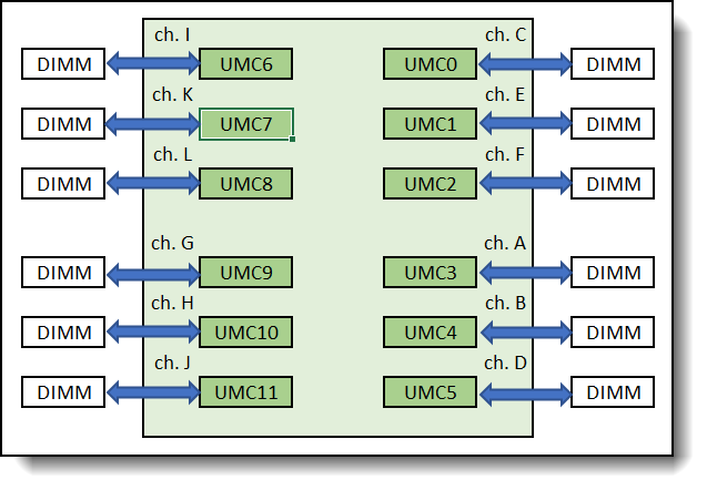
Figure 1. 5th Gen AMD EPYC Processor – logical view
Figure 2 illustrates the layout of the physical DIMM slots on Lenovo servers that support 5th Gen AMD EPYC Processor. As shown, on one side of the processor socket, DIMM slot connected to channel G is the closest DIMM slot to the processor socket, followed by channel H, I, J, K. Channel L is the farthest DIMM slot from the processor socket. On the other side of the processor socket, DIMM slot connected to channel A is the closest to the processor socket, and DIMM slot connected to channel F is the farthest from the processor socket.
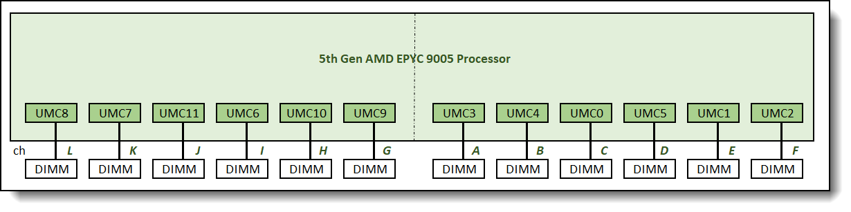
Figure 2. 5th Gen AMD EPYC Processor – physical DIMM layout view
We will use both views of the processor to help illustrate the DIMM population and memory interleaving for all memory configurations.
To illustrate various memory topologies for a processor, different memory configurations will be designated as L:K:J:I:H:G:A:B:C:D:E:F where each letter indicates the number of memory DIMMs populated on each memory channel.
- A refers to Memory Channel 3 on UMC3
- B refers to Memory Channel 4 on UMC4
- C refers to Memory Channel 0 on UMC0
- D refers to Memory Channel 5 on UMC5
- E refers to Memory Channel 1 on UMC1
- F refers to Memory Channel 2 on UMC2
- G refers to Memory Channel 9 on UMC9
- H refers to Memory Channel 10 on UMC10
- I refers to Memory Channel 6 on UMC6
- J refers to Memory Channel 11 on UMC11
- K refers to Memory Channel 7 on UMC7
- L refers to Memory Channel 8 on UMC8
The order of the DIMM sequence in the notation also maps to the actual physical order sequence of the DIMM slots as shown in figure 2 above.
As an example, a 1:0:1:0:1:0:1:0:1:0:1:0 memory configuration has 1 DIMM populated on Memory Channels L, J, H, A, C, and E. Channels K, I, G, B, D, and F are left unpopulated.
Memory Interleaving
The 5th Gen AMD EPYC processor family optimizes memory accesses by creating interleave sets across the memory controllers and memory channels. For example, if two memory channels were populated with the same total memory capacity and the same number of ranks, a 2-channel interleave set is created across the two memory channels.
Interleaving enables higher memory bandwidth by spreading contiguous memory accesses across all memory channels in a memory interleave set rather than sending all memory accesses to one memory channel. This allows the processors to access multiple memory channels simultaneously. In order to form an interleave set, all channels are required to have the same DIMM type, the same total memory capacity and ranks.
For EPYC 9005 processors, the number of memory channels in an interleave set has to be 2, 4, 6, 8, 10, or 12.
If one interleave set cannot be formed for a particular memory configuration, it is possible to have multiple interleave sets. When this happens, memory bandwidth performance is dependent on the specific memory region being accessed and how many DIMMs comprise the interleave set. For this reason, memory bandwidth performance on memory configurations with multiple interleave sets can be inconsistent. Contiguous memory accesses to a memory region with fewer channels in the interleave set will have lower performance compared to accesses to a memory region with more channels in the interleave set.
Figure 3 illustrates a 2-channel interleave set which results from populating identical memory DIMMs on channel A and channel G. This 2-channel interleave set interleaves data line across memory controllers and between memory channels. Consecutive addresses alternate between the two memory controllers.
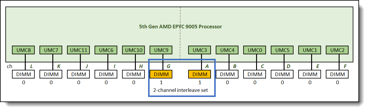
Figure 3. 2-channel interleave set across 2 memory controllers and between 2 memory channels
Balanced Memory Configurations
Balanced memory configurations enable optimal memory interleaving which maximizes memory bandwidth performance. The basic guidelines for a balanced memory subsystem are as follows:
- The number of populated memory channels per socket should be 1, 2, 4, 6, 8, 10, or 12.
- All populated memory channel should have the same memory configuration. Since only 1DPC is supported on Lenovo servers with support for 5th Gen AMD EPYC processors, it means all populated memory channels should have identical DIMMs.
- All processor sockets on the same physical server should have the same DIMM configuration.
- All NUMA domains in the same processor socket need to have identical memory configuration. This applies when the processor is set to NPS2 or NPS4 (NPS = Numa node per socket).
We will refer to the above guidelines as balanced memory guidelines 1, 2, 3, and 4 throughout this paper.
Performance Test Benchmark
STREAM Triad is a simple, synthetic benchmark designed to measure sustainable memory bandwidth throughput. The goal is to measure the highest memory bandwidth supported by the system. STREAM Triad will be used to measure the sustained memory bandwidth of various memory configurations discussed in this paper. Unless otherwise stated, all test configurations were done using 64GB 2R RDIMMs running at 6400MHz.
For more information about STREAM Triad, see the following web page:
http://www.cs.virginia.edu/stream/
As described in the Memory Interleaving section, it is possible to get inconsistent memory bandwidth performance when there are multiple interleave sets in a memory configuration. To account for this behavior, we configure each test run to make sure the STREAM benchmark accesses the entire memory address map. The reported test result reflects the average memory bandwidth performance for these configurations. In reality, memory bandwidth performance in configurations with multiple interleave sets can be unpredictable, depending on which interleave set is being accessed. For this reason, we also provide memory bandwidth measurement for the worst case. This happens when memory in the interleave set with the lowest number of memory channels is being accessed.
Supported Memory Configurations
With 5th Gen AMD EPYC Processors, the following memory configurations are supported on Lenovo servers.
In our lab study, we used a 2-socket server, but the findings should be applicable to both 1-socket and 2-socket servers. We will limit this study to cover just the supported memory configurations listed in Table 1 above. We will start with the assumption that balanced memory guideline 3 (described in the Balanced memory configurations section) is followed, i.e. all processor sockets on the same physical server have the same configurations of memory DIMMs. Therefore, we only describe memory configuration for one processor. The other processor will have identical memory configuration.
In the first part of our study, all the DIMMs were 64GB dual-rank RDIMMs (met balanced memory guideline 2), and we populated 1, 2, 4, 6, 8, 10, and 12 DIMMs per socket (met balanced memory guideline 3). Processor is set to NPS1 so guideline 4 does not apply. This means all memory configurations covered in this part of the paper are balanced memory configurations.
For more information on supported DIMM types and DIMM configurations, please refer to the Lenovo Press product guides:
- 1U and 2U rack servers:
- ThinkSystem SR635 V3: https://lenovopress.lenovo.com/lp1609
- ThinkSystem SR655 V3: https://lenovopress.lenovo.com/lp1610
- ThinkSystem SR645 V3: https://lenovopress.lenovo.com/lp1607
- ThinkSystem SR665 V3: https://lenovopress.lenovo.com/lp1608
- HPC servers
- ThinkSystem SR675 V3: https://lenovopress.lenovo.com/lp1611
- ThinkSystem SD665 V3: https://lenovopress.lenovo.com/lp1612
- ThinkSystem SD665-N V3: https://lenovopress.lenovo.com/lp1613
Configuration with 1 DIMM
We start with only one memory DIMM populated in 0:0:0:0:0:0:1:0:0:0:0:0 configuration as shown in Figure 4 below.
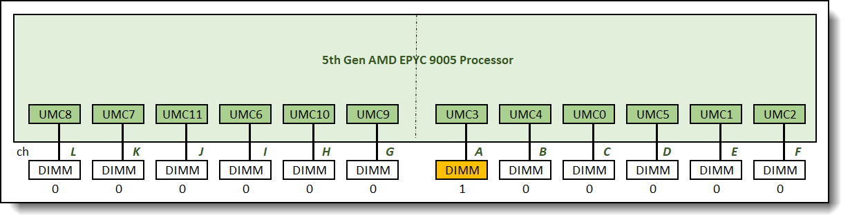
Figure 4. 0:0:0:0:0:0:1:0:0:0:0:0 memory configuration relative memory bandwidth: 9%
Only one memory channel was populated with memory DIMM in this configuration. Utilizing only one of the twelves memory channels available limits the memory bandwidth support of this configuration to 9% of the full potential memory bandwidth this processor can support.
The best way to increase memory bandwidth from this configuration is by using more lower density DIMMs. Two 32GB RDIMMs populated on two memory channels, or four 16GB RDIMMs on four memory channels would provide the same memory capacity while greatly improve memory bandwidth support by a factor or two or four respectively.
Configuration with 2 DIMMs
The recommended and supported memory configuration with four memory DIMMs is the 0:0:0:0:0:1:1:0:0:0:0:0 memory configuration as shown in Figure 5.
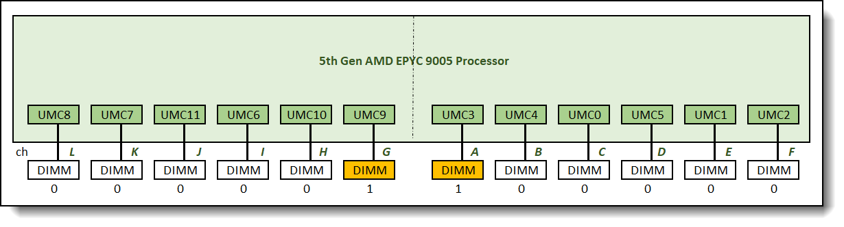
Figure 5. 0:0:0:0:0:1:1:0:0:0:0:0 memory configuration relative memory bandwidth: 18%
One 2-channel interleave set is formed across the two memory channels in this memory configuration. Only two memory channels are populated with memory which reduces memory bandwidth of this memory configuration to about one sixth of the full potential memory bandwidth. It was measured at 18% of the maximum achievable memory bandwidth supported by the processor.
The best way to increase memory bandwidth in this configuration is to utilize lower density DIMMs to increase the number of populated memory channels while maintaining the same capacity.
Configuration with 4 DIMMs
The recommended and supported memory configuration with four memory DIMMs is the 0:0:0:1:0:1:1:0:1:0:0:0 memory configuration as shown in Figure 6.
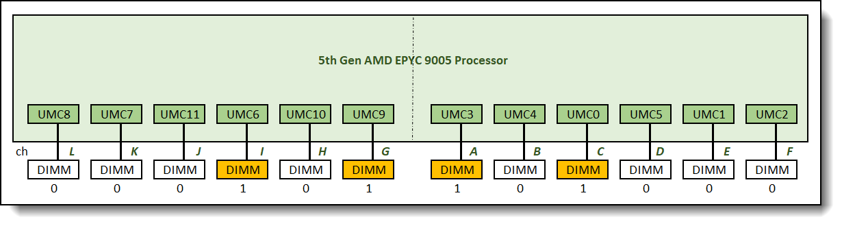
Figure 6. 0:0:0:1:0:1:1:0:1:0:0:0 memory configuration relative memory bandwidth: 35%
One 4-channel interleave set is formed across 4 memory channels in this configuration. Memory bandwidth was measured at 35% of the maximum achievable memory bandwidth supported by the processor.
Configuration with 6 DIMMs
The recommended and supported memory configuration with six memory DIMMs is the 0:0:0:1:1:1:1:1:1:0:0:0 memory configuration as shown in Figure 7.
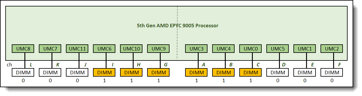
Figure 7. 0:0:0:1:1:1:1:1:1:0:0:0 memory configuration relative memory bandwidth: 52%
One 6-channel interleave set is formed across 6 memory channels in this configuration. Memory bandwidth was measured at 52% of the maximum achievable memory bandwidth supported by the processor.
Configuration with 8 DIMMs
The recommended and supported memory configuration with eight memory DIMMs is the 0:1:0:1:1:1:1:1:1:0:1:0 memory configuration as shown in Figure 8.
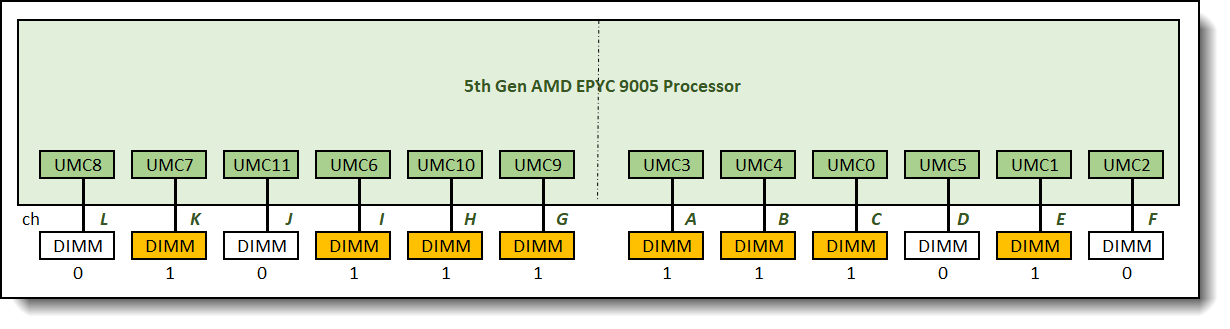
Figure 8. 0:1:0:1:1:1:1:1:1:0:1:0 memory configuration relative memory bandwidth: 69%
One 8-channel interleave set is formed across 8 memory channels in this configuration. Memory bandwidth was measured at 69% of the maximum achievable memory bandwidth supported by the processor.
Configuration with 10 DIMMs
The recommended and supported memory configuration with ten memory DIMMs is the 0:1:1:1:1:1:1:1:1:1:1:0 memory configuration as shown in Figure 9.
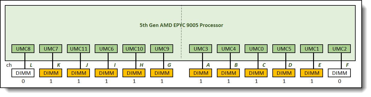
Figure 9. 0:1:1:1:1:1:1:1:1:1:1:0 memory configuration relative memory bandwidth: 85%
One 10-channel interleave set is formed across 10 memory channels in this configuration. Memory bandwidth was measured at 85% of the maximum achievable memory bandwidth supported by the processor
Configuration with 12 DIMMs
This is a fully populated configuration 1:1:1:1:1:1:1:1:1:1:1:1 as shown in Figure 10.
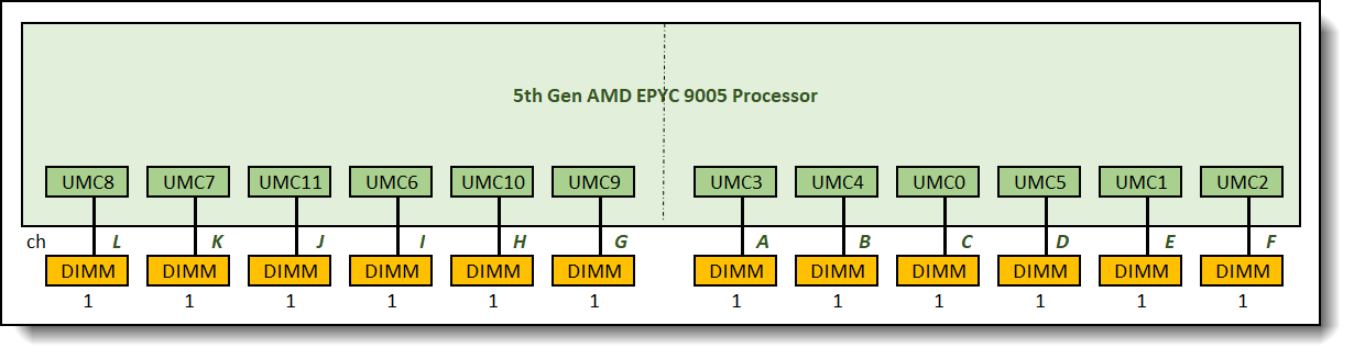
Figure 10. 1:1:1:1:1:1:1:1:1:1:1:1 memory configuration relative memory bandwidth: 100%
One 12-channel interleave set is formed across all 12 memory channels in this configuration. Memory bandwidth reached the maximum achievable memory bandwidth supported by the processor
Summary of the Performance Results
The following table shows the summary of the relative memory bandwidths of all supported memory configurations that were evaluated. As mentioned before, these memory configurations are balanced configurations with NPS1 setting. One memory interleave set is formed and memory bandwidth performance is consistent in all configurations.
Balanced Memory Configuration with different NPS settings
All examples above were with NPS1 setting (NPS1 = 1 NUMA node per socket). This mean there is only one node or one memory partition in each processor socket. With NPS1, all memory configurations discussed above are balanced memory configurations. However, that might not be the case when the system is set to NPS2 or NPS4. When the system is set to NPS2 or NPS4, we need to take guideline 4 into consideration. As listed above, guideline 4 states that all NUMA domains in the same processor socket need to have identical memory configuration.
Let’s take a few examples to explain this further.
Example 1 – Configuration with 12 DIMMs
Logical view of this memory configuration is as shown in Figure 11.
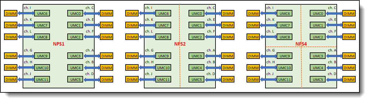
Figure 11. Configuration with 12 DIMMs – balanced memory configuration with NPS1/NPS2/NPS4
The dotted red lines show the partitions within the processor socket when it is set to NPS2 and NPS4. In this memory configuration, DIMM configurations are identical in each node for both NPS2 and NPS4 settings. This memory configuration is a balanced memory configuration for NPS1, NPS2, and NPS4.
Example 2 – Configuration with 10 DIMMs
Logical view of this memory configuration is as shown in Figure 12.
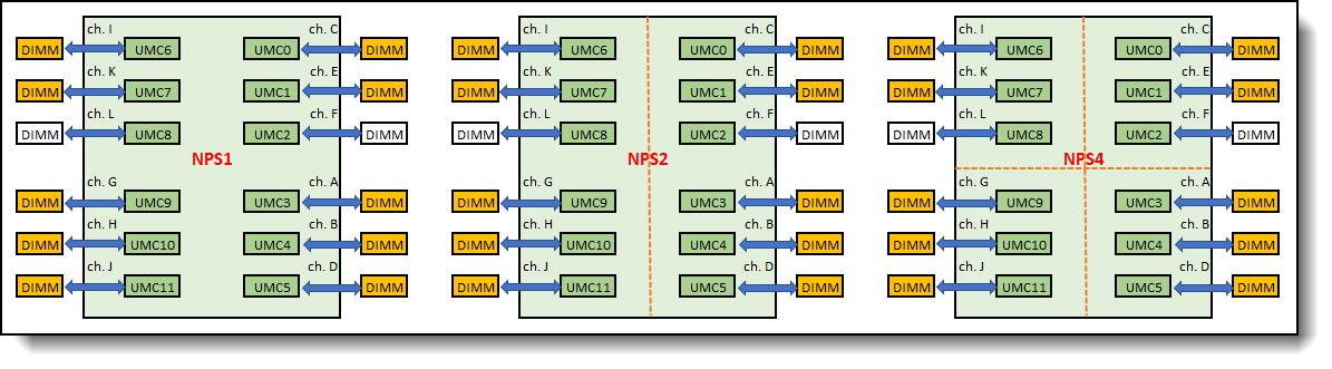
Figure 12. Configuration with 10 DIMMs – balanced memory configuration with NPS1 and NPS2, but not with NPS4
In this memory configuration, DIMM configurations are identical in each node for NPS2, but not NPS4. With NPS4, two nodes have 3 DIMMs populated, and two other nodes have only 2 DIMMs populated. Taking guideline 4 into account, this memory configuration is balanced with NPS1 and NPS2, but it is not a balanced memory configuration with NPS4. With NPS4, the cores in the nodes with the 3-channel interleave set will have direct local access to higher memory bandwidth compared to the cores in the nodes with 2-channel interleave set.
Balanced Memory Configuration Summary
Table 3 shows the summary of whether a memory configuration is balanced with different NPS settings.
Maximizing Memory Bandwidth
To maximize memory bandwidth of a server, the following rules should be followed:
- Balanced the memory across the processor sockets – all processor sockets on the same physical server should have the same memory DIMM configuration.
- Balance the memory across the memory controllers – all memory controllers on a processor socket should have the same memory DIMM configuration.
- Balance the memory across the populated memory channels – all populated memory channels should have the same total memory capacity and the same total number of ranks.
All Lenovo server offerings with 5th Gen AMD EPYC Processors support one DIMM slot per DDR channel (1DPC). Peak memory bandwidth performance is achieved when each processor socket is populated with 12 identical DIMMs.
For optimal memory bandwidth configuration, follow these steps:
- Determine the required memory capacity per socket.
- Divide this memory capacity by twelve to determine the minimum memory capacity needed per DDR channel.
- Round this calculated memory capacity per channel to the nearest DIMM capacity.
- Populated each processor socket with twelve identical DIMMs with the capacity determined in the step above.
Example:
A 1TB total memory capacity is required for SR665 V3, which supports two processors. Follow the steps highlighted above:
- Memory capacity required per socket = 1TB / 2-sockets = 512GB.
- Memory capacity required per DDR channel = 512GB / 12 DDR channels = 42.67GB.
- Round up to the next available DIMM capacity = 64GB DIMM.
- Populated this server with 24x 64GB DIMMs.
Mixed Capacity DIMM Memory Configurations
Our balanced memory configuration guideline 2 states that all populated memory channel should have the same memory configuration. This often means using the same DIMM to populate all memory channels. However, there are cases where, despite our recommendations, the customer had a memory capacity requirement that cannot be met with a balanced memory configuration.
One of such examples is a mixed capacity DIMM memory configuration, i.e. DDR channels are populated with different DIMM capacities. In this case, it is an unbalanced memory configuration with multiple memory interleave sets. This results in non-optimal memory performance. We will provide an example and walk through one such configuration to help illustrate the performance impact.
Example: A customer has a memory capacity requirement of 576GB per socket.
If we follow our recommendations above for a balanced memory configuration, the memory configuration that meets this capacity requirement is the one shown in the figure below. Each processor socket is populated with twelve 64GB DIMMs, for a total of 64GB x 12 = 768GB per socket. This configuration has more memory capacity than required. It is a balanced memory configuration. It has one interleave set and achieves maximum supported memory bandwidth.
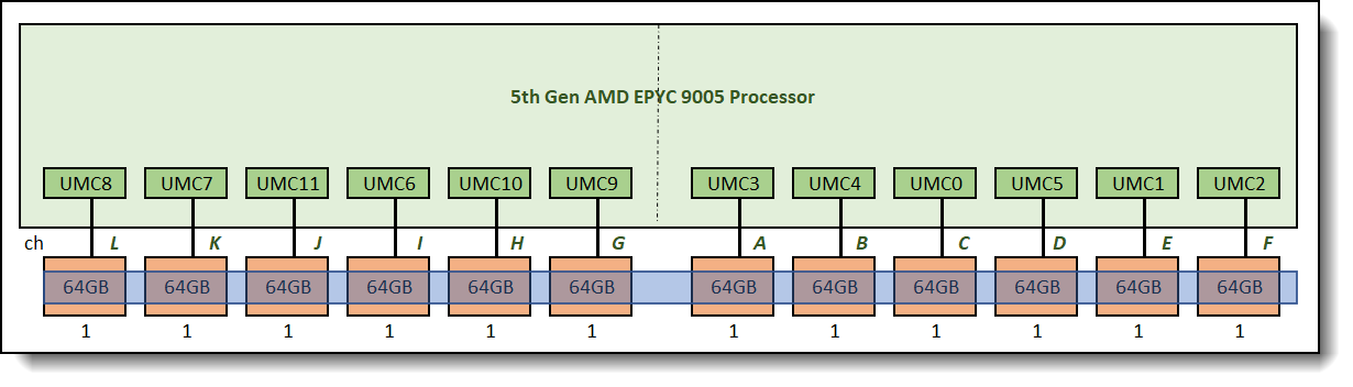
Figure 13. Balanced memory configuration, total capacity = 768GB vs requirement = 576GB, relative bandwidth: 100%
If the customer insists on having a memory configuration with the exact memory capacity required, one might go with a memory configuration as shown in Figure 14 below. This configuration does not follow our guideline 2 and it is an unbalanced configuration. Two memory interleave sets are formed as shown in Figure 14.
Memory bandwidth performance in this configuration is not consistent and is dependent on which interleave set is being accessed.
The size of the "fully interleaved portion" of the memory controller = minimum channel capacity × number of channels. When channel capacities are inconsistent, interleaving can only be performed using the smallest channel capacity. The remaining "extra capacity of the larger DIMM" is called overhang. This area cannot participate in the uniform interleaving of all channels and can only be accessed on a few channels. If the overhang is concentrated on a small number of channels, accessing this area will result in reduced bandwidth (because only a portion of the channels are used).
In this example, the average memory bandwidth performance for this configuration is 75% of the maximum possible bandwidth supported, but it could get as low as 51% of the maximum bandwidth when the smaller interleave set with 6-channel (the yellow interleave set) is being accessed.
For those light-load scenarios, if your application only uses a small portion of total memory (for example, less than 384GB), the performance impact may be minimal. However, for scenarios involving heavy loads or large data, accessing the additional 192GB can lead to bandwidth bottlenecks or increased access latency, ultimately affecting overall system performance. For memory-intensive applications, such as scientific computing, virtualization, and large databases, which are very sensitive to memory bandwidth and latency, an asymmetric configuration may become a bottleneck.
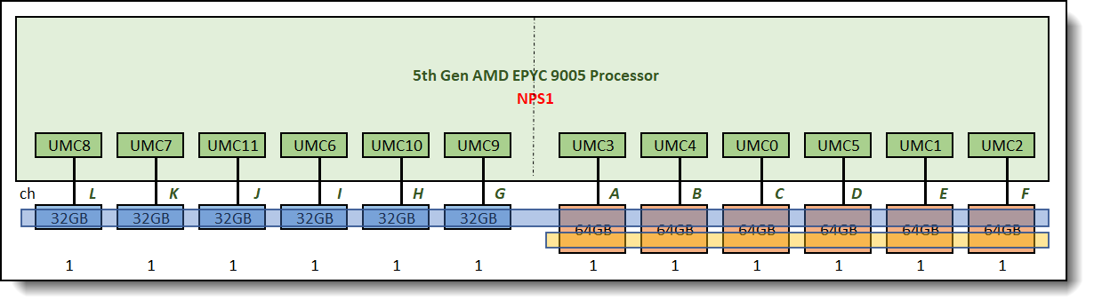
Figure 14. Unbalanced memory configuration using NPS1, one set of 12-way memory interleave and one set of 6-way memory interleave
If the application is optimized for strong NUMA local access (such as HPC, low-latency transactions, and in-memory databases), consider using NPS=2 or NPS=4 for better local bandwidth (per-node bandwidth). Bandwidth is primarily determined by the number of channels and frequency, and is independent of the capacity of a single DIMM (32GB vs. 64GB) (assuming the DIMM speed is the same).
At NPS=2, each NUMA node has six memory channels, forming two sets of 6-way memory interleaving as shown in Figure 15. In local access scenarios (data resides on the node where the process resides), the peak memory bandwidth of Node 0 and Node 1 are the same (both 6 channels), regardless of whether the DIMMs are 32GB or 64GB. In terms of local throughput, 32G memory channel and 64G memory channel nodes have equivalent peak performance at NPS=2.
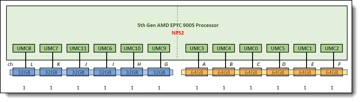
Figure 15. Unbalanced memory configuration using NPS2, two sets of 6-way memory interleave
At NPS=4, each NUMA node has three memory channels, forming four sets of 3-way memory interleaving as shown in Figure 16. Node 0, Node1,Node2 and Node 3 are the same (both 3 channels). If the application can be bound to a single node and memory usage does not exceed the local node's memory capacity, performance is not affected.
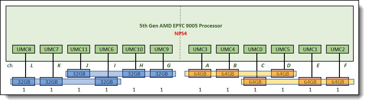
Figure 16. Unbalanced memory configuration using NPS4, four sets of 3-way memory interleave
Figure 17 shows alternating memory configurations of varying capacities. Similar to Figure 14, the NPS 1 configuration also creates a 12-way memory interleave and a 6-way memory interleave. Unlike Figure 14, the overhang is not concentrated on the same CPU side. When the memory working set exceeds 384GB and overhang access is required, still only six channels are available. However, the alternating layout prevents all overhang traffic from being confined to the same side of the CPU, overhang channels are distributed throughout the physical topology of the CPU, allowing the memory controller to schedule them more evenly and reduce access hotspots. Compared to Figure 14, where performance decreases stepwise after entering the overhang zone, Figure 17 will have a more gradual performance decrease, resulting in better average performance.
Interleaved memory installation is not ideal for NUMA-aware applications when using NPS2 and NPS4, as it results in more overhang areas compared to Figures 15 and 16, thus impacting local node bandwidth.
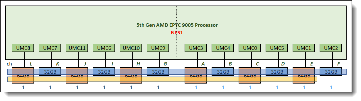
Figure 17. Unbalanced memory configuration using NPS1, one set of 12-way memory interleave and one set of 6-way memory interleave
Summary
Overall server performance is affected by the memory subsystem which can provide both high memory bandwidth and low memory access latency when properly configured. Balancing memory across the memory controllers and the memory channels produces memory configurations which can efficiently interleave memory references among its DIMMs, producing the highest possible memory bandwidth. An unbalanced memory configuration can reduce the total memory bandwidth to as low as 9% of a balanced memory configuration with 12 identical DIMMs installed per processor.
Implementing all three (or four for NPS2 and NPS4) of the balanced memory guidelines described in this paper results in balanced memory configurations producing the best possible memory bandwidth and overall performance.
Using mixed memory capacities is not recommended, as it results in an unbalanced memory configuration. If mixed memory capacities are necessary and the application is NUMA-aware, consider using NPS2 or NPS4 and placing the same capacity memory on the same NUMA node to avoid memory overhang and achieve optimal local node bandwidth. If the application is not NUMA-aware, when using NPS1, full interleaving will only occur on the minimum memory capacity of each channel. A portion of the larger capacity memory will have overhangs, which will affect performance when accessing this portion. Alternating memory installation can distribute overhang memory channels across the physical topology of the CPUs, allowing the memory controller to schedule them more evenly, performance degradation caused by an unbalanced configuration will be more gradual.
Authors
This paper was produced by the following team of performance specialists:
Peter Xu is a Systems Performance Verification Engineer in the Lenovo Infrastructure Solutions Group Performance Laboratory in Morrisville, NC, USA. His current role includes CPU, Memory, and PCIe subsystem analysis and performance validation against functional specifications and vendor targets. Peter holds a Bachelor of Electronic and Information Engineering and a Master of Electronic Science and Technology, both from Hangzhou Dianzi University.
Kai Yang is a Performance Engineer in the Lenovo Infrastructure Solutions Group Laboratory in Taipei Taiwan. Kai joined Lenovo in June 2023. Prior to this, he worked at Quanta Computer as System Integration Test Specialist, for verifying Intel & AMD platform server function, debugging and analyzing critical system defects. His current role includes CPU and Memory analysis and performance validation against functional specifications and vendor targets. Kai holds a Master’s Degree in Information Management from National Kaohsiung First University of Science and Technology in Taiwan, and a Bachelor’s Degree in Information Management from I-SHOU University, Taiwan.
This paper is based on the Lenovo Press paper, Balanced Memory Configurations with 4th Generation AMD EPYC Processors. Thanks to the authors:
- Nathan Pham
- Peter Xu
Balanced Memory papers
This paper is one of a series of papers on Balanced Memory configurations:
Intel processor-based servers:
- Balanced Memory Configurations for 2-Socket Servers with 4th and 5th Gen Intel Xeon Scalable Processors
- Balanced Memory Configurations for 2-Socket Servers with 3rd Gen Intel Xeon Scalable Processors
- Balanced Memory Configurations with 2nd Gen Intel Xeon Scalable Processors
- Balanced Memory Configurations with 1st Generation Intel Xeon Scalable Processors
- Maximizing System x and ThinkServer Performance with a Balanced Memory Configuration
AMD processor-based servers:
Trademarks
Lenovo and the Lenovo logo are trademarks or registered trademarks of Lenovo in the United States, other countries, or both. A current list of Lenovo trademarks is available on the Web at https://www.lenovo.com/us/en/legal/copytrade/.
The following terms are trademarks of Lenovo in the United States, other countries, or both:
Lenovo®
System x®
ThinkServer®
ThinkSystem®
The following terms are trademarks of other companies:
AMD and AMD EPYC™ are trademarks of Advanced Micro Devices, Inc.
Intel® and Xeon® are trademarks of Intel Corporation or its subsidiaries.
NPS® is a trademark of IBM in the United States, other countries, or both.
Other company, product, or service names may be trademarks or service marks of others.
Configure and Buy
Please select a locale
Full Change History
Course Detail
Employees Only Content
The content in this document with a is only visible to employees who are logged in. Logon using your Lenovo ITcode and password via Lenovo single-signon (SSO).
The author of the document has determined that this content is classified as Lenovo Internal and should not be normally be made available to people who are not employees or contractors. This includes partners, customers, and competitors. The reasons may vary and you should reach out to the authors of the document for clarification, if needed. Be cautious about sharing this content with others as it may contain sensitive information.
Any visitor to the Lenovo Press web site who is not logged on will not be able to see this employee-only content. This content is excluded from search engine indexes and will not appear in any search results.
For all users, including logged-in employees, this employee-only content does not appear in the PDF version of this document.
This functionality is cookie based. The web site will normally remember your login state between browser sessions, however, if you clear cookies at the end of a session or work in an Incognito/Private browser window, then you will need to log in each time.
If you have any questions about this feature of the Lenovo Press web, please email David Watts at dwatts@lenovo.com.


