

Top
Author
Published
2 Jul 2024Form Number
LP1977PDF size
41 pages, 1.6 MBSubscribed to LP1977.
Thank you for your feedback.
Table of Contents
Abstract
Properly configuring UEFI parameters in a server is important for achieving a desired outcome such as maximum performance or maximum energy efficiency. This paper defines preset UEFI operating modes for Lenovo® ThinkSystem™ servers running AMD EPYC 9004 Series processors that are optimized for each of these outcomes. In addition, a thorough explanation is provided for each of the UEFI parameters so they can be fine-tuned for any particular customer deployment.
This paper is for customers and for business partners and sellers wishing to understand how to optimize UEFI parameters to achieve maximum performance or energy efficiency of Lenovo ThinkSystem servers with 4th Gen AMD EPYC processors.
Introduction
The Lenovo ThinkSystem UEFI provides an interface to the server firmware that controls boot and runtime services. The system firmware contains numerous tuning parameters that can be set through the UEFI interface. These tuning parameters can affect all aspects of how the server functions and how well the server performs.
The UEFI in ThinkSystem contains operating modes that pre-define tuning parameters for maximum performance or maximum energy efficiency. This paper describes the 4th Gen AMD EPYC processor tuning parameter settings for each operating mode and other tuning parameters to consider for performance and efficiency.
Note: The focus of this paper is the parameters and settings applicable to the ThinkSystem SR635 V3, SR645 V3, SR655 V3, SR665 V3 servers, however most (if not all) discussions equally apply to all ThinkSystem V3 servers with AMD EPYC 9004 processors.
Tuning UEFI series
This paper is one in a series on the tuning of UEFI settings on ThinkSystem servers
- Tuning UEFI on servers with AMD processors
- Tuning UEFI on servers with Intel processors:
Summary of operating modes
The ThinkSystem SR635 V3, SR655 V3, SR645 V3 and SR665 V3 servers with 4th Gen AMD EPYC processors offer two preset operating modes, Maximum Efficiency and Maximum Performance. These modes are a collection of predefined low-level UEFI settings that simplify the task of tuning the server for either maximum performance or energy efficiency.
The two pre-defined modes are as follows:
- Maximum Efficiency (the default): Maximizes performance/watt efficiency while maintaining reasonable performance
- Maximum Performance: Achieves maximum performance at the expense of higher power consumption and lower energy efficiency
The following table summarizes the settings that are made for each mode selected. The values in the Category column (column 3) in each table are as follows:
- Recommended: Settings follow Lenovo’s best practices and should not be changed without sufficient justification.
- Suggested: Settings follow Lenovo’s general recommendation for a majority of workloads but these settings can be changed if justified by workload specific testing.
- Test: The non-default values for the Test settings can optionally be evaluated because they are workload dependent.
| Menu Item | Category | Setting for maximum efficiency | Setting for maximum performance |
|---|---|---|---|
| Operating Mode | Recommended | Maximum Efficiency | Maximum Performance |
| Determinism Slider | Recommended | Performance | Power |
| Core Performance Boost | Recommended | Enabled | Enabled |
| cTDP | Recommended | Auto | Maximum cTDP supported by the CPU |
| Package Power Limit | Recommended | Auto | Maximum cTDP supported by the CPU |
| Memory Speed | Recommended | Maximum 4800 | Maximum 4800 |
| Efficiency Mode | Recommended | Enabled | Disabled |
| 4-Link xGMI Max Speed 3-Link xGMI Max Speed (Only for 2 socket system) |
Recommended | Minimum The value is 20 GT/s |
Maximum The value is 32 GT/s |
| Global C-state Control | Recommended | Enabled | Enabled |
| DF P-states | Recommended | Auto | Auto |
| DF C-States | Recommended | Enabled | Enabled |
| MONITOR/MWAIT | Recommended | Enabled | Enabled |
| P-State | Recommended | Enabled | Disabled |
| Memory Power Down Enable | Recommended | Enabled | Enabled |
| CPU Speculative Store Modes (Hidden setting) |
Recommended | Balanced | More Speculative |
The following table lists additional UEFI settings that you should consider for tuning for performance or energy efficiency. These settings are not part of the Maximum Efficiency and Maximum Performance modes.
| Menu Item | Category | Comments |
|---|---|---|
| Memory Interleave | Suggested | It is recommended to keep Enabled as default. |
| xGMI Maximum Link Width (Only for 2 socket system) |
Suggested | It is recommended to keep Auto as default. |
| NUMA Nodes per Socket | Suggested | Optionally experiment with NPS2 or NPS4 for NUMA optimized workloads. |
| SMT Mode | Suggested | It is recommended to keep Enabled as default. Disabled for HPC and low latency/jitter workloads |
| L1 Stream HW Prefetcher | Suggested | Optionally experiment with Disabled for maximum efficiency |
| L2 Stream HW Prefetcher | Suggested | Optionally experiment with Disabled for maximum efficiency |
| L1 Stride Prefetcher | Test | Optionally experiment with Disabled for maximum efficiency |
| L1 Region Prefetcher | Test | Optionally experiment with Disabled for maximum efficiency |
| L2 Up/Down Prefetcher | Test | Optionally experiment with Disabled for maximum efficiency |
| ACPI SRAT L3 Cache as NUMA Domain | Suggested | Optionally experiment with Enabled for NUMA optimized workloads |
| PCIe Gen Speed Selection | Suggested | Suggest keep Maximum |
| CPPC | Suggested | Suggest keep Enabled |
| BoostFmax | Suggested | Suggest keep Auto |
| DRAM Scrub Time | Suggested | Suggest keep 24 hour interval |
| Number of Enabled CPU Cores Per Socket | Suggested | It is recommended to keep All as default. |
| ACPI CST C2 Latency | Test | Larger C2 latency values will reduce the number of C2 transitions and reduce C2 residency. |
| PCIe Ten Bit Tag Support | Suggested | Suggest keep Enabled as default |
| Periodic Directory Rinse (PDR) Tuning | Test | Optionally experiment with Cache-Bound for well-behaved, long-running, cache-bound workloads. |
| xGMI Force Link Width (Hidden setting, only for 2 socket system) |
Test | Optionally experiment with x8 or x4 for those applications that are not sensitive to socket-to-socket bandwidth and latency. |
How to use OneCLI and Redfish
In addition to using UEFI Setup, Lenovo also provides OneCLI/ASU variables and Redfish UEFI Setting Attribute names for managing system settings.
The methods to use OneCLI/ASU variables and Redfish attributes are as follows:
- OneCLI/ASU variable usage
Show current setting:
Onecli config show "<OneCLI/ASU Var>" --override --log 5 --imm <userid>:<password>@<IP Address>
Example:
onecli config show "OperatingModes.ChooseOperatingMode" --override --log 5 --imm USERID:PASSW0RD@10.240.218.89
Set a setting:
Onecli config set "<OneCLI/ASU Var>" "<choice>" –override –log 5 –imm <userid>:<password>@<IP Address>
Example:
onecli config set "OperatingModes.ChooseOperatingMode" "Maximum Efficiency" --override --log 5 --imm USERID:PASSW0RD@10.240.218.89
- Redfish Attributes configure URL
Setting get URL: https://<BMC IP>/redfish/v1/Systems/Self/Bios
Setting set URL: https://<BMC IP>/redfish/v1/Systems/Self/Bios/SDExample:
Get URL: https://10.240.55.226/redfish/v1/Systems/Self/Bios
Set URL: https://10.240.55.226/redfish/v1/Systems/Self/Bios/SD - Redfish Value Names of Attributes
If no special description, choice name is same as possible values. If there is a space character (‘ ‘), dash character (‘-‘) or forward slash character (‘/’) in the possible values, replace them with underline (“_”). This is because the Redfish standard doesn’t support those special characters.
If you use OneCLI to configure the setting, OneCLI will automatically replace those characters with an underline character. However, if you use other Redfish tools, then you may need to replace them manually.
For example, “Operating Mode” has three choices: Maximum Efficiency, Maximum Performance and Custom Mode, their Redfish value names are MaximumEfficiency, MaximumPerformance and CustomMode.
The latest onecli can be obtained from the following link:
https://support.lenovo.com/us/en/solutions/ht116433-lenovo-xclarity-essentials-onecli-onecli
For more detailed information on the BIOS schema, please refer to the DMTF website:
https://redfish.dmtf.org/redfish/schema_index
Usually, postman can be used for get/set BIOS schema:
https://www.getpostman.com/
The remaining sections in this paper provide details about each of these settings. We describe how to access the settings via System Setup (Press F1 during system boot).
UEFI menu items
The following items are provided to server administrators in UEFI menus that are accessible by pressing F1 when a server is booted, through the XClarity Controller (XCC) service processor, or through command line utilities such as Lenovo’s Advanced Settings Utility (ASU) or OneCLI.
These parameters are made available because they are regularly changed from their default values to fine tune server performance for a wide variety of customer use cases.
Menu items described in this paper for ThinkSystem V3 servers with 4th Gen AMD EPYC 9004 series processors are as follows:
Operating Mode
This setting is used to set multiple processor and memory variables at a macro level.
Choosing one of the predefined Operating Modes is a way to quickly set a multitude of processor, memory, and miscellaneous variables. It is less fine grained than individually tuning parameters but does allow for a simple “one-step” tuning method for two primary scenarios.
Tip: Prior to optimizing a workload for maximum performance, it is recommended to set the Operating Mode to “Maximum Performance” and then reboot rather than simply starting from the Maximum Efficiency default mode and then modifying individual UEFI parameters. If you don’t do this, some settings may be unavailable for configuration.
This setting is accessed as follows:
- System setup: System Settings → Operating Modes → Choose Operating Mode
- OneCLI/ASU variable: OperatingModes.ChooseOperatingMode
- Redfish attribute: OperatingModes_ChooseOperatingMode
Default Setting: Maximum Efficiency
Possible values:
- Maximum Efficiency
Maximizes the performance / watt efficiency with a bias towards power savings.
- Maximum Performance
Maximizes the absolute performance of the system without regard for power savings. Most power savings features are disabled, and additional memory power / performance settings are exposed.
- Custom Mode
Allow user to customize the performance settings. Custom Mode will inherit the UEFI settings from the previous preset operating mode. For example, if the previous operating mode was the Maximum Performance operating mode and then Custom Mode was selected, all the settings from the Maximum Performance operating mode will be inherited.
Settings for Processors
In this section:
- Determinism Slider
- Core Performance Boost
- cTDP (Configurable TDP)
- PPL (Package Power Limit)
- xGMI settings
- xGMI Maximum Link Width
- 4-Link xGMI Max Speed or 3-Link xGMI Max Speed
- Global C-State Control
- DF (Data Fabric) P-states
- DF (Data Fabric) C-States
- MONITOR/MWAIT
- P-State
- SMT Mode
- Data Prefetchers
- ACPI SRAT L3 Cache as NUMA Domain
- CPPC
- BoostFmax
- Number of Enabled CPU Cores Per Socket
- ACPI CST C2 Latency
- Periodic Directory Rinse (PDR) Tuning
Determinism Slider
The determinism slider allows you to select between uniform performance across identically configured systems in your data center (by setting all servers to the Performance setting) or maximum performance of any individual system but with varying performance across the data center (by setting all servers to the Power setting).
4th Gen AMD EPYC processors default to Performance Determinism mode to help ensure consistent performance results across a population of systems. It can help ensure each platform can achieve this consistent level of performance.
When setting Determinism to Performance, ensure that cTDP and PPL are set to the same value (see Configurable TDP control and PPL (Package Power Limit) for more details). The default (Auto) setting for most processors will be Performance Determinism mode.
In the Power Determinism mode, EPYC CPUs can increase boost frequency above the default levels seen with Performance Determinism mode. As a result, in compute heavy workloads some EPYC CPUs may operate at or near the thermal control point the CPU uses. This is standard operation that is not expected to impact reliability and does not impact the warranty of the EPYC CPU.
Also note that the actual performance achieved by the CPU in Power Determinism mode should always be greater or equal to the result achieved in Performance Determinism mode. This is true even if the CPU operates at the thermal control point continuously.
This setting is accessed as follows:
- System setup:
- System Settings → Operating Modes → Determinism Slider
- System Settings → Processors → Determinism Slider
- OneCLI/ASU variable: Processors.DeterminismSlider
- Redfish: Processors_DeterminismSlider
Possible values:
- Power
Ensure maximum performance levels for each CPU in a large population of identically configured CPUs by throttling CPUs only when they reach the same cTDP. Forces processors that are capable of running at the rated TDP to consume the TDP power (or higher).
- Performance (default)
Ensure consistent performance levels across a large population of identically configured CPUs by throttling some CPUs to operate at a lower power level.
Core Performance Boost
Core Performance Boost (CPB) is similar to Intel Turbo Boost Technology. CPB allows the processor to opportunistically increase a set of CPU cores higher than the CPU’s rated base clock speed, based on the number of active cores, power and thermal headroom in a system.
Consider using CPB when you have applications that can benefit from clock frequency enhancements. Avoid using this feature with latency-sensitive or clock frequency-sensitive applications, or if power draw is a concern. Some workloads do not need to be able to run at the maximum capable core frequency to achieve acceptable levels of performance.
To obtain better power efficiency, there is the option of setting a maximum core boost frequency. This setting does not allow you to set a fixed frequency. It only limits the maximum boost frequency. If the BoostFmax is set to something higher than the boost algorithms allow, the SoC will not go beyond the allowable frequency that the algorithms support.
This setting is accessed as follows:
- System setup:
- System Settings → Operating Modes → Core Performance Boost
- System Settings → Processors → Core Performance Boost
- OneCLI/ASU variable: Processors.CorePerformanceBoost
- Redfish: Processors_CorePerformanceBoost
Possible values:
- Disabled
Disables Core Performance Boost so the processor cannot opportunistically increase a set of CPU cores higher than the CPU’s rated base clock speed.
- Enabled (default)
When set to Enable, cores can go to boosted P-states.
cTDP (Configurable TDP)
Configurable Thermal Design Power (cTDP) allows you to modify the platform CPU cooling limit. A related setting, Package Power Limit (PPL), discussed in the next section, allows the user to modify the CPU Power Dissipation Limit.
Many platforms will configure cTDP to the maximum supported by the installed CPU. For example, an EPYC 9654 part has a default TDP of 360 W but has a cTDP maximum of 400 W. Most platforms also configure the PPL to the same value as the cTDP. Please refer to AMD EPYC Processor cTDP Range Table to get maximum cTDP of your installed processor.
If the Determinism slider parameter is set to Performance (see Determinism slider), cTDP and PPL must be set to the same value, otherwise, the user can set PPL to a value lower than cTDP to reduce system operating power. The CPU will control CPU boost to keep socket power dissipation at or below the specified Package Power Limit.
For maximum performance, set cTDP and PPL to the maximum cTDP value supported by the CPU. For increased energy efficiency, set cTDP and PPL to Auto which sets both parameters to the CPU’s default TDP value.
This setting is accessed as follows:
- System setup:
- System Settings → Operating Modes → cTDP
- System Settings → Processors → cTDP
- OneCLI/ASU variable: Processors.cTDP
- Redfish: Processors_cTDP
Possible values:
- Auto (default)
Use the platform and the default TDP for the installed processor. cTDP = TDP.
- Maximum
Maximum sets the maximum allowed cTDP value for the installed CPU SKU. Maximum could be greater than default TDP. Please refer to 32 for maximum cTDP of each CPU SKU.
- Manual
Set customized configurable TDP. Set the configurable TDP (in Watts). If a manual value is entered that is larger than the max value allowed, the value will be internally limited to the maximum allowable value.
PPL (Package Power Limit)
The parameter sets the CPU package power limit. The maximum value allowed for PPL is the cTDP limit. Set PPL to the cTDP Maximum value when maximum performance is desired. PPL can be set to the cTDP Minimum value or lower but reaching the set value of PPL is not guaranteed when it is set to less than cTDP Minimum.
This setting is accessed as follows:
- System setup:
- System Settings → Operating Modes → Package Power Limit
- System Settings → Processors → Package Power Limit
- OneCLI/ASU variable: Processors.PackagePowerLimit
- Redfish: Processors_PackagePowerLimit
Possible values:
- Auto (default)
Set to maximum value allowed by installed CPU
- Maximum
The maximum value allowed for PPL is the cTDP limit.
- Manual
If a manual value entered that is larger than the maximum value allowed (cTDP Maximum), the value will be internally limited to maximum allowable value.
xGMI settings
xGMI (Global Memory Interface) is the Socket SP5 processor socket-to-socket interconnection topology comprised of four x16 links. Each x16 link is comprised of 16 lanes. Each lane is comprised of two unidirectional differential signals.
Since xGMI is the interconnection between processor sockets, these xGMI settings are not applicable for ThinkSystem SR635 V3, SR655 V3, and SD535 V3 which are one-socket platforms.
NUMA-unaware workloads may need maximum xGMI bandwidth/speed while other compute efficient NUMA-aware platforms may be able to minimize the xGMI speed and achieve adequate performance with power savings from the lower speed. The xGMI speed can be lowered, link width can be reduced from x16 to x8,x4.
The following two settings affect the xGMI links:
xGMI Maximum Link Width
Sets the xGMI width of all the links.
This setting is accessed as follows:
- System setup: System Settings → Processors → xGMI Maximum Link Width
- OneCLI/ASU variable: Processors.xGMIMaximumLinkWidth
- Redfish: Processors_xGMIMaximumLinkWidth
Possible values:
- Auto (default)
Auto sets maximum width based on the system capabilities. For the SR665 V3 and SR645 V3, the maximum link width is set to 16.
- x4
Sets the maximum link width to x4.
- x8
Sets the maximum link width to x8.
- x16
Sets the maximum link width to x16
4-Link xGMI Max Speed or 3-Link xGMI Max Speed
The following 2S systems use 4-Link xGMI:
- ThinkSystem SR645 V3
- ThinkSystem SR665 V3
- ThinkSystem SD665 V3
- ThinkSystem SD665-N V3
The SR665 V3 also can optionally be configured as 3-Link xGMI by removing one from the motherboard, which provides 16 more PCIe I/O lanes as shown in the SR665 V3 block diagram in the ThinkSystem server platform design section.
The following 2S systems use 3-Link xGMI:
- ThinkSystem SR675 V3
- ThinkSystem SR685a V3
The xGMI Max Speed setting is used to set the xGMI speed, thereby maximizing socket-to-socket interconnection performance. For NUMA-aware workloads, users can also lower the xGMI speed setting to reduce power consumption.
This setting is accessed as follows:
- System setup:
- System Settings → Operating Modes → 4-Link xGMI Max Speed (or 3-Link xGMI Max Speed)
- System Settings → Processors → 4-Link xGMI Max Speed (or 3-Link xGMI Max Speed)
- OneCLI/ASU variable:
- Processors.4-LinkxGMIMaxSpeed
- Processors.3-LinkxGMIMaxSpeed
- Redfish:
- Processors_4_LinkxGMIMaxSpeed
- Processors_3_LinkxGMIMaxSpeed
Possible values:
- 32Gbps
- 25Gbps
- Minimum (default, 20 Gbps)
Global C-State Control
C-states are idle power saving states. This setting enables and disables C-states on the server across all cores. When disabled, the CPU cores can only be in C0 (active) or C1 state. C1 state can never be disabled. A CPU core is considered to be in C1 state if the core is halted by the operating system.
Lenovo generally recommends that Global C-State Control remain enabled, however consider disabling it for low-jitter use cases.
This setting is accessed as follows:
- System setup:
- System Settings → Operating Modes → Global C-state Control
- System Settings → Processors → Global C-state Control
- OneCLI/ASU variable: Processors.GlobalC-stateControl
- Redfish: Processors_GlobalC_stateControl
Possible values:
- Disabled
I/O based C-state generation and Data Fabric (DF) C-states are disabled.
- Enabled (default)
I/O based C-state generation and DF C-states are enabled.
DF (Data Fabric) P-states
Infinity Fabric is a proprietary AMD bus that connects all the Core Cache Dies (CCDs) to the IO die inside the CPU. DF P-states is the Infinity Fabric (Uncore) Power States setting. When Auto is selected the CPU DF P-states will be dynamically adjusted. That is, their frequency will dynamically change based on the workload. Selecting P0, P1, P2 forces the Infinity Fabric to a specific P-state frequency.
DF P-states functions cooperatively with the Algorithm Performance Boost (APB) which allows the Infinity Fabric to select between a full-power and low-power fabric clock and memory clock based on fabric and memory usage. Latency sensitive traffic may be impacted by the transition from low power to full power. Setting APBDIS to 1 (to disable APB) and DF P-states=0 sets the Infinity Fabric and memory controllers into full-power mode. This will eliminate the added latency and jitter caused by the fabric power transitions.
The following examples illustrate how DF P-states and APBDIS function together:
- If DF P-states=Auto then APBDIS=0 will be automatically set. The Infinity Fabric can select between a full-power and low-power fabric clock and memory clock based on fabric and memory usage.
- If DF-P-states=<P0, P1, P2> then APBDIS=1 will be automatically set. The Infinity Fabric and memory controllers are set in full-power mode.
- If DF P-states=P0 which results in APBDIS=1, the Infinity Fabric and memory controllers are set in full-power mode. This results in the highest performing Infinity Fabric P-state with the lowest latency jitter.
This setting is accessed as follows:
- System setup:
- System Settings → Operating Modes → DF P-states
- System Settings → Processors → DF P-states
- OneCLI/ASU variable: Processors.SOCP-states
- Redfish: Processors_SOCP_states
Possible values:
- Auto (default)
When Auto is selected the CPU DF P-states (uncore P-states) will be dynamically adjusted.
- P0: Highest-performing Infinity Fabric P-state
- P1: Next-highest-performing Infinity Fabric P-state
- P2: Minimum Infinity Fabric P-state
DF (Data Fabric) C-States
Much like CPU cores, the Infinity Fabric can go into lower power states while idle. However, there will be a delay changing back to full-power mode causing some latency jitter. In a low latency workload, or one with bursty I/O, one could disable this feature to achieve more performance with the tradeoff of higher power consumption.
This setting is accessed as follows:
- System setup:
- System Settings → Operating Modes → DF C-States
- System Settings → Processors → DF C-States
- OneCLI/ASU variable: Processors.DFC-States
- Redfish: Processors_DFC_States
Possible values:
- Enabled (default)
Enable Data Fabric C-states. Data Fabric C-states may be entered when all cores are in CC6.
- Disabled
Disable Data Fabric (DF) C-states.
MONITOR/MWAIT
Some operating systems engage C-states by using MONITOR/WAIT instructions and not the ACPI table. These operating systems will still enter higher C-states even if the C-States UEFI parameter is Disabled. To prevent this, suggest disabling MONITOR/MWAIT. This setting can only be configured when Global C-state Control is disabled.
This setting is accessed as follows:
- System setup:
- System Settings → Operating Modes → MONITOR/MWAIT
- System Settings → Processors → MONITOR/MWAIT
- OneCLI/ASU variable: Processors.MONITORMWAIT
- Redfish: Processors_MONITORMWAIT
Possible values:
- Enabled (default)
Enable MONITOR/MWAIT.
- Disabled
Disable MONITOR/MWAIT.
P-State
This setting enables or disable the CPU's P-State
This setting is accessed as follows:
- System setup:
- System Settings → Operating Modes → P-State
- System Settings → Processors → P-State
- OneCLI/ASU variable: Processors.P-state
- Redfish: Processors_P_state
Possible values:
- Enabled (default)
Core frequency can move between SKU-specific predefined P-States based on its utilization to balance performance and power usage.
- Disabled
Sets the core frequency to the highest-available frequency within P0.
SMT Mode
Simultaneous multithreading (SMT) is similar to Intel Hyper-Threading Technology, the capability of a single core to execute multiple threads simultaneously. An OS will register an SMT-thread as a logical CPU and attempt to schedule instruction threads accordingly. All processor cache within a Core Complex (CCX) is shared between the physical core and its corresponding SMT-thread.
In general, enabling SMT benefits the performance of most applications. Certain operating systems and hypervisors, such as VMware ESXi, are able to schedule instructions such that both threads execute on the same core. SMT takes advantage of out-of-order execution, deeper execution pipelines and improved memory bandwidth in today’s processors to be an effective way of getting all of the benefits of additional logical CPUs without having to supply the power necessary to drive a physical core.
Start with SMT enabled since SMT generally benefits the performance of most applications, however, consider disabling SMT in the following scenarios:
- Some workloads, including many HPC workloads, observe a performance neutral or even performance negative result when SMT is enabled.
- Using multiple execution threads per core requires resource sharing and is a possible source of inconsistent system response. As a result, disabling SMT could give benefit on some low-jitter use case.
- Some application license fees are based on the number of hardware threads enabled, not just the number of physical cores present. For this reason, disabling SMT on your EPYC 9004 Series processor may be desirable to reduce license fees.
- Some older operating systems that have not enabled support for the x2APIC within the EPYC 9004 Series processor, which is required to support beyond 384 threads. If you are running an operating system that does not support AMD's x2APIC implementation, and have two 96-core processors installed, you will need to disable SMT.
- Operating systems such as Windows Server 2012 and Windows Server 2016 do not support x2APIC. Please refer to the following article for details:
https://support.microsoft.com/en-in/help/4514607/windows-server-support-and-installation-instructions-for-amd-rome-proc
This setting is accessed as follows:
- System setup: System Settings → Processors → SMT Mode
- OneCLI/ASU variable: Processors.SMTMode
- Redfish: Processors_SMTMode
Possible values:
- Disabled
Disables simultaneous multithreading so that only one thread or CPU instruction stream is run on a physical CPU core
- Enabled (default)
Enables simultaneous multithreading.
Data Prefetchers
There are five prefetchers described here:
- L1 Stream Prefetcher: Uses history of memory access patterns to fetch next line into the L1 cache when cached lines are reused within a certain time period or access sequentially.
- L1 Stride Prefetcher: Uses memory access history to fetch additional data lines into L1 cache when each access is a constant distance from previous.
- L1 Region Prefetcher: Uses memory access history to fetch additional data line into L1 cache when the data access for a given instruction tends to be followed by a consistent pattern of subsequent access.
- L2 Stream Prefetcher: Uses history of memory access patterns to fetch next line into the L2 cache when cached lines are reused within a certain time period or access sequentially.
- L2 Up/Down Prefetcher: Uses memory access history to determine whether to fetch the next or previous line for all memory accesses.
These prefetchers use memory access history to determine whether to fetch the next or previous line for all memory access. Most workloads will benefit from these prefetchers gathering data and keeping the core pipeline busy. By default, these prefetchers all are enabled.
Application information access patterns, which tend to be relatively predictable, benefit greatly from prefetching. Most typical line-of-business, virtualization and scientific applications benefit from having prefetcher enabled, however, there are some workloads (for example, the SPECjbb 2015 Java application benchmark) that are very random in nature and will actually obtain better overall performance by disabling some of the prefetchers.
Further, the L1 and L2 stream hardware prefetchers can consume disproportionately more power vs. the gain in performance when enabled. Customers should therefore evaluate the benefit of prefetching vs. the non-linear increase in power if sensitive to energy consumption.
This setting is accessed as follows:
- System setup:
- System Settings → Processors → L1 Stream HW Prefetcher
- System Settings → Processors → L2 Stream HW Prefetcher
- System Settings → Processors → L1 Stride Prefetcher
- System Settings → Processors → L1 Region Prefetcher
- System Settings → Processors → L2 Up/Down Prefetcher
- OneCLI/ASU variables:
- Processors.L1StreamHWPrefetcher
- Processors.L2StreamHWPrefetcher
- Processors.L1StridePrefetcher
- Processors.L1RegionPrefetcher
- Processors.L2UpDownPrefetcher
- Redfish:
- Processors_L1StreamHWPrefetcher
- Processors_L2StreamHWPrefetcher
- Processors_L1StridePrefetcher
- Processors_L1RegionPrefetcher
- Processors_L2UpDownPrefetcher
Possible values:
- Disabled: Disable corresponding Prefetcher.
- Enabled (default): Enable corresponding Prefetcher.
ACPI SRAT L3 Cache as NUMA Domain
When it is enabled, each Core Complex (CCX) in the system will become a separate NUMA domain. This setting can improve performance for highly NUMA optimized workloads if workloads or components of workloads can be pinned to cores in a CCX and if they can benefit from sharing an L3 cache. When disabled, NUMA domains will be identified according to the NUMA Nodes per Socket parameter setting.
This setting is accessed as follows:
- System setup: System Settings → Processors → ACPI SRAT L3 Cache as NUMA Domain
- OneCLI/ASU variable: Processors.ACPISRATL3CacheasNUMADomain
- Redfish: Processors_ACPISRATL3CacheasNUMADomain
Possible values:
- Disabled (default)
When disabled, NUMA domains will be identified according to the NUMA Nodes per Socket parameter setting.
- Enabled
When enabled, each Core Complex (CCX) in the system will become a separate NUMA domain.
CPPC
CPPC (Cooperative Processor Performance Control) was introduced with ACPI 5.0 as a mode to communicate performance between an operating system and the hardware. This mode can be used to allow the OS to control when and how much turbo can be applied in an effort to maintain energy efficiency. Not all operating systems support CPPC, but Microsoft began support with Windows Server 2016.
This setting is accessed as follows:
- System setup: System Settings → Processors → CPPC
- OneCLI/ASU variable: Processors.CPPC
- Redfish: Processors_CPPC
Possible values:
- Enabled (default)
- Disabled
BoostFmax
This value specifies the maximum boost frequency limit to apply to all cores. If the BoostFmax is set to something higher than the boost algorithms allow, the SoC will not go beyond the allowable frequency that the algorithms support.
This setting is accessed as follows:
- System setup: System Settings → Processors → BoostFmax
- OneCLI/ASU variable:
- BoostFmax
- Processors.BoostFmaxManual (for specifying the frequency number)
- Redfish:
- Processors_BoostFmax
- Processors_BoostFmaxManual (for specifying the frequency number)
Possible values:
- Manual
A 4 digit number representing the maximum boost frequency in MHz.
If you use OneCLI (or Redfish), first set Processors.BoostFmax (or Redfish Attribute Processors_BoostFmax) to Manual, then specify the maximum boost frequency number in MHz to Processors.BoostFmaxManual (or Redfish Attribute Processors_BoostFmaxManual).
- Auto (default)
Auto set the boost frequency to the fused value for the installed CPU.
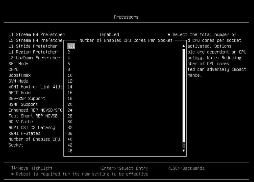
Number of Enabled CPU Cores Per Socket
UEFI allows the administrator to shut down cores in a server. This setting powers off a set number of cores for each processor in a system. As opposed to restricting the number of logical processors an OS will run on, this setting directly affects the number of cores powered on by turning off the core level power gates on each processor.
Manipulating the number of physically powered cores is primarily used in three scenarios:
- Where users have a licensing model that supports a certain number of active cores in a system
- Where users have poorly threaded applications but require the additional LLC available to additional processors, but not the core overhead.
- Where users are looking to limit the number of active cores in an attempt to reclaim power and thermal overhead to increase the probability of Performance Boost being engaged.
This setting is accessed as follows:
- System setup: System Settings → Processors → Number of Enabled CPU Cores Per Socket
- OneCLI/ASU variable: Processors.NumberofEnabledCPUCoresPerSocket
- Redfish: Processors_NumberofEnabledCPUCoresPerSocket
Possible values:
- All (default): Enable all cores
- (Any core count value based on the CCDs and Cores Per CCD in your server)
The following figure shows an example of the selction of possible values:
ACPI CST C2 Latency
ACPI CST C2 Latency affects how quickly the cores can go to sleep when idle. The faster the cores go to sleep when idle, the more power can be applied to the active cores and the runtime drop. The best value will depend on the OS kernel version, use case and workload.
This setting is accessed as follows:
- System setup: System Settings → Processors → ACPI CST C2 Latency
- OneCLI/ASU variable: Processors.ACPICSTC2Latency
- Redfish attribute: Processors_ACPICSTC2Latency
Possible values for ACPI CST C2 Latency:
- 800 (default)
- Enter a value between 18 and 1000 in microseconds as a decimal value
Periodic Directory Rinse (PDR) Tuning
To ensure long-term performance stability, EPYC Infinity Fabric constantly rinses the coherence directory at a low frequency. All cached data gets invalidated at a corresponding frequency. If invalidated data is still useful, it needs to be re-fetched. This setting can control the frequency of rinse and help manage directory capacity more efficiently for different application scenarios.
This setting is accessed as follows:
- System setup: System Settings → Processors → Periodic Directory Rinse (PDR) Tuning
- OneCLI/ASU variable: Processors.PeriodicDirectoryRinsePDRTuning
- Redfish attribute: Processors_PeriodicDirectoryRinsePDRTuning
Possible values for Periodic Directory Rinse Tuning:
- Auto (default):
Use silicon reset value, it’s Memory-Sensitive for Genoa.
- Memory-Sensitive
This is the highest rinse frequency supported in the BIOS. Expect small-to-zero performance loss in cache-bound workloads.
- Cache-Bound
This is the lowest rinse frequency supported in BIOS, similar to the Milan frequency. It can result in large performance losses in a narrow class of memory-bound workloads.
- Adaptive
Adjusts based on Memory/Cache Activity. Dynamically achieves the best of memory-bound and cache-bound.
- Neutral
Fallback option for unknown or mixed scenarios.
Settings for Memory
In this section:
Memory Speed
The memory speed setting determines the frequency at which the installed memory will run. Consider changing the memory speed setting if you are attempting to conserve power, since lowering the clock frequency to the installed memory will reduce overall power consumption of the DIMMs.
With the fourth-generation AMD EPYC processors, setting the memory speed to 4800 MHz does not result in higher memory latency when compared to operation at 3600 MHz. The highest memory performance is achieved when the memory speed is set to 4800 MHz and the memory DIMMs are capable of operating at 4800 MHz.
This setting is accessed as follows:
- System setup:
- System Settings → Memory → Memory Speed
- System Information → System Summary → Memory Speed
- OneCLI/ASU variable: Memory.MemorySpeed
- Redfish: Memory_MemorySpeed
Possible values:
- Maximum (default)
The actual maximum supported speed and is auto-calculated based on the CPU SKU, DIMM type, number of DIMMs installed per channel, and the capability of the system.
- 4800 MHz
- 4400 MHz
- 4000 MHz
- Minimum
The system operates at the rated speed of the slowest DIMM in the system when populated with different speed DIMMs.
Memory Power Down Enable
Low-power feature for DIMMs. Lenovo generally recommends that Memory Power Down remain enabled, however consider disabling it for low-latency use cases.
This setting is accessed as follows:
- System setup:
- System Settings → Operating Modes → Memory Power Down Enable
- System Settings → Memory → Memory Power Down Enable
- OneCLI/ASU variable: Memory.MemoryPowerDownEnable
- Redfish: Memory_MemoryPowerDownEnable
Possible values:
- Enabled (default)
Enables low-power features for DIMMs.
- Disabled
Memory Interleave
This setting allows interleaved memory accesses across multiple memory channels in each socket, providing higher memory bandwidth. Interleaving generally improves memory performance so the Enabled setting is recommended.
This setting is accessed as follows:
- System setup: System Settings → Memory → Interleave
- OneCLI/ASU variable: Memory.Interleave
- Redfish attribute: Memory_Interleave
Possible values for Memory Interleave:
- Enabled (default)
- Disabled
NUMA Nodes per Socket
This setting lets you specify the number of desired NUMA nodes per socket. NPS0 will attempt to interleave the two sockets together into one NUMA node.
AMD EPYC 9004 processors support a varying number of NUMA Nodes per Socket depending on the internal NUMA topology of the processor. In one-socket servers, the number of NUMA Nodes per socket can be 1, 2 or 4 though not all values are supported by every processor. See Table 4 for the NUMA nodes per socket options available for each processor.
Applications that are highly NUMA optimized can improve performance by setting the number of NUMA Nodes per Socket to a supported value greater than 1.
This setting is accessed as follows:
- System setup: System Settings → Memory → NUMA Nodes per Socket
- OneCLI/ASU variable: Memory.NUMANodesperSocket
- Redfish: Memory_NUMANodesperSocket
Possible values:
- NPS0
NPS0 will attempt to interleave the 2 CPU sockets together (non-NUMA mode).
- NPS1 (default)
One NUMA node per socket.
Available for any CCD configuration in the SoC.
Preferred Interleaving: 12-channel interleaving using all channels in the socket.
- NPS2
Two NUMA nodes per socket, one per Left/Right Half of the SoC.
Requires symmetrical CCD configuration across left/right halves of the SoC.
Preferred Interleaving: 6-channel interleaving using channels from each half.
- NPS4
Four NUMA nodes per socket, one per Quadrant.
Requires symmetrical Core Cache Die (CCD) configuration across Quadrants of the SoC.
Preferred Interleaving: 3-channel interleaving using channels from each quadrant.
DRAM Scrub Time
Memory reliability parameter that sets the period of time between successive DRAM scrub events. Performance may be reduced with more frequent DRAM scrub events.
This setting is accessed as follows:
- System setup: System Settings → Memory → DRAM Scrub Time
- OneCLI/ASU variable: Memory.DRAMScrubTime
- Redfish: Memory_DRAMScrubTime
Possible values:
- Disabled
- 1 hour
- 4 hour
- 8 hour
- 16 hour
- 24 hour (default)
- 48 hour
Settings for Power
In this section:
Efficiency Mode
This setting enables an energy efficient mode of operation internal to the 4th Gen AMD EPYC processors at the expense of performance. The setting should be enabled when energy efficient operation is desired from the processor. Set it to Disabled when maximum performance is desired.
This setting is accessed as follows:
- System setup:
- System Settings → Operating Modes → Efficiency Mode
- System Settings → Power → Efficiency Mode
- OneCLI/ASU variable: Power.EfficiencyMode
- Redfish: Power_EfficiencyMode
Possible values:
- Disabled
Use performance optimized CCLK DPM settings.
- Enabled (default)
Use power efficiency optimized CCLK DPM settings.
Settings for Devices and I/O Ports
In this section:
PCIe Gen Speed Selection
Choose the generation speed for available PCIe slots. Set the PCIe slot as Auto or generation 1, 2, 3, 4 or 5.
This setting is accessed as follows:
- System setup:
- For slots System Settings → Devices and I/O Ports → PCIe Gen Speed Selection → Slot N
- For NVMe: System Settings → Devices and I/O Ports → PCIe Gen Speed Selection → NVMe Bay N
- OneCLI/ASU variable:
- For slots DevicesandIOPorts.PCIeGen_SlotN (N is the slot number, for example PCIeGen_Slot4
- For NVMe: DevicesandIOPorts.PCIeGen_ NVMeBayN (where N is the bay number)
- Redfish:
- For slots: DevicesandIOPorts_PCIeGen_SlotN (N is the slot number)
- For NVMe: DevicesandIOPorts_PCIeGen_NVMeBayN (N is the bay number)
Possible values:
- Auto (default): Maximum PCIe speed by installed PCIE device support.
- Gen1: 2.5 GT/s
- Gen2: 5.0 GT/s
- Gen3: 8.0 GT/s
- Gen4: 16.0 GT/s
- Gen5: 32.0 GT/s
PCIe Ten Bit Tag Support
This setting enables the PCIe Ten Bit Tag which is optionally supported by PCIe device since Gen4. Enable Ten Bit Tag to increase the number of non-posted request from 256 to 768 for better performance. As latency increases, the increase in unique tags is required to maintain the peak performance at 16GT/s.
This setting is accessed as follows:
- System setup: System Settings → Devices and I/O Ports → PCIe Ten Bit Tag Support
- OneCLI/ASU variable: DevicesandIOPorts.PCIeTenBitTagSupport
- Redfish attribute: DevicesandIOPorts_PCIeTenBitTagSupport
Possible values for PCIe Ten Bit Tag:
- Enabled (default)
- Disabled
Hidden UEFI Items
The UEFI items in this section are more limited in their applicability to customer use cases and are not exposed in UEFI menus. However, they can be accessed using the command line utilities such as Lenovo’s Advanced Settings Utility (ASU) or OneCLI.
CPU Speculative Store Modes
Speculative execution is an optimization technique in which a processor performs a series of tasks to prepare information for use if required. The store instructions tell the processor to transfer data from a register to a specific memory location. This setting will impact how fast the store instructions send invalidations to the remote cache line.
This setting is accessed as follows:
- OneCLI/ASU variable: Processors.CPUSpeculativeStoreModes
- Redfish attribute: Processors_CPUSpeculativeStoreModes
Possible values for CPU Speculative Store Mode:
- Balanced (default)
Store instructions may delay sending out their invalidations to remote cacheline copies when the cacheline is present but not in a writable state in the local cache.
- More Speculative
Store instructions will send out invalidations to remote cacheline copies as soon as possible.
- Less Speculative
Store instructions may delay sending out their invalidations to remote cacheline copies when the cacheline is not present in the local cache or not in a writable state in the local cache.
xGMI Force Link Width
Setting xGMI Force Link Width eliminates any such latency jitter. Applications that are not sensitive to both socket-to-socket bandwidth and latency can use a forced link width of 8 or 4 to save power, which can divert more power to the cores for boost.
If xGMI Force Link Width Control is changed from its default of Auto, the xGMI Max Link Width setting won’t work since the xGMI link is constantly forced to the static value.
This setting is accessed as follows:
- OneCLI/ASU variable: Processors.xGMIForceLinkWidth
- Redfish attribute: Processors_xGMIForceLinkWidth
Possible values for CPU xGMI Force Link Width:
- Auto(default)
- x16
- x8
- x4
Low Latency and Low Jitter UEFI parameter settings
The tables in this section show the recommended settings when tuning for either Low Latency or Low Jitter.
The Low Latency settings should be used when a workload or application relies on the lowest possible local/remote memory, storage, and/or PCIe adapter latency.
The Low Jitter settings should be used when minimal run-to-run and system-to-system variation is desired, i.e. more consistent performance.
Note that peak performance may be impacted to achieve lower latency or more consistent performance.
Tip: Prior to optimizing a workload for Low Latency or Low Jitter, it is recommended you first set the Operating Mode to “Maximum Performance”, save settings, then reboot rather than simply starting from the Maximum Efficiency default mode and then modifying individual UEFI parameters. If you don’t do this, some settings may be unavailable for configuration.
| Menu Item | Category | Low Latency | Low Jitter |
|---|---|---|---|
| Determinism Slider | Recommended | Power | Performance |
| Core Performance Boost | Recommended | Enabled | Disabled |
| cTDP | Recommended | Maximum | Maximum |
| Package Power Limit | Recommended | Maximum | Maximum |
| Memory Speed | Recommended | 4800 | 4800 |
| Memory Interleave | Recommended | Enabled | Enabled |
| Efficiency Mode | Recommended | Disabled | Enabled |
| 4-Link xGMI Max Speed 3-Link xGMI Max Speed |
Recommended | 32Gbps | 32Gbps |
| xGMI Maximum Link Width | Recommended | Auto | x16 |
| Global C-state Control | Recommended | Enabled | Disabled |
| DF P-states | Recommended | P0 | P0 |
| DF C-States | Recommended | Enabled | Disabled |
| P-State | Recommended | Disabled | Disabled |
| Memory Power Down Enable | Recommended | Disabled | Disabled |
| NUMA Nodes per Socket | Test | NPS=4; Note that available NPS options vary depending on processor SKU and the number of DIMMs installed. Set to the highest available NPS setting. | NPS1 (Optionally experiment with NPS=2 or NPS=4 for NUMA optimized workloads) |
| SMT Mode | Test | Disabled | Disabled |
| ACPI SRAT L3 Cache as NUMA Domain | Test | Disabled (Optionally experiment with if application threads can be pinned to a NUMA node and can share an L3 cache) |
Disabled (Optionally experiment with if application threads can be pinned to a NUMA node and can share an L3 cache) |
| CPPC | Recommended | Enabled | Disabled |
| DRAMScrubTime | Recommended | Disabled | Disabled |
| CPU Speculative Store Modes | Test | More Speculative | Balanced |
ThinkSystem server platform design
The following figures show the block diagrams of the 4th Gen AMD EPYC processor-based ThinkSystem servers, SR635 V3, SR655 V3, SR645 V3 and SR665 V3 for reference. For other servers, see the respective procuct guide.
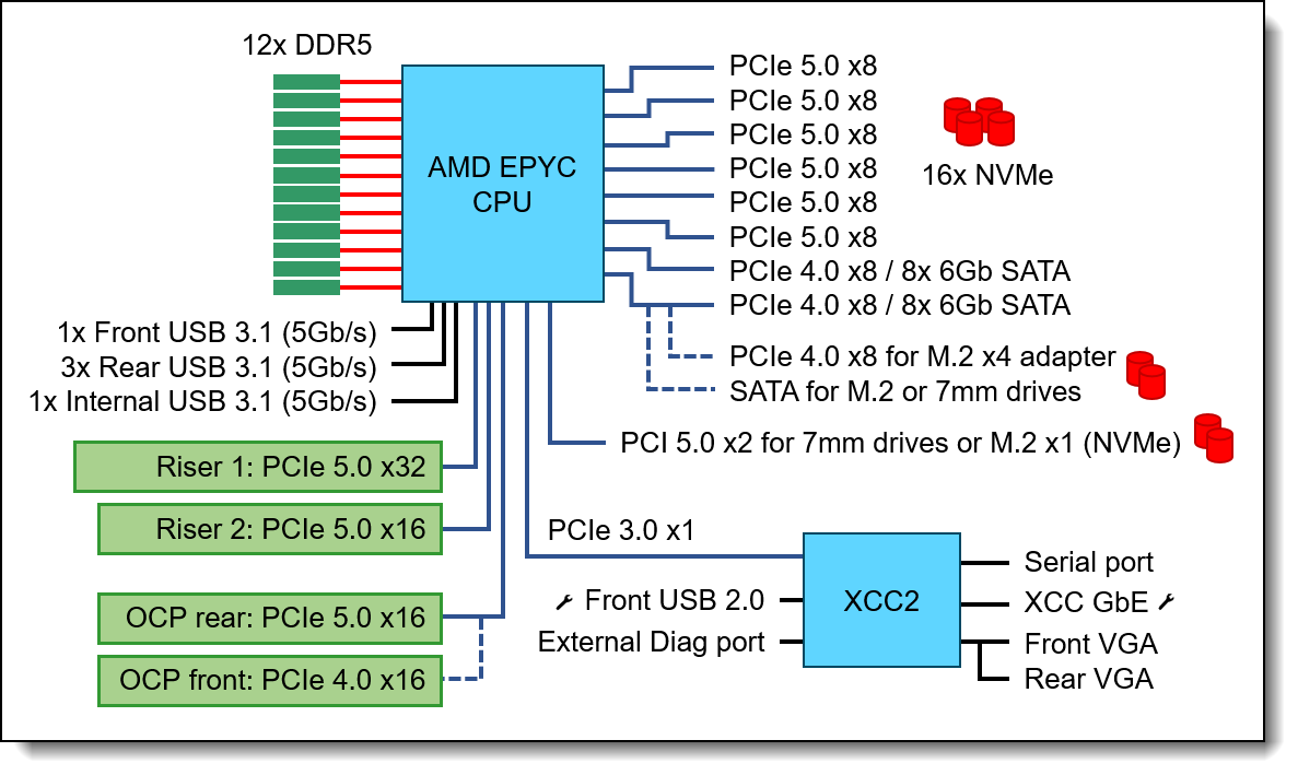
Figure 2. SR635 V3 (1U 1S) system architectural block diagram
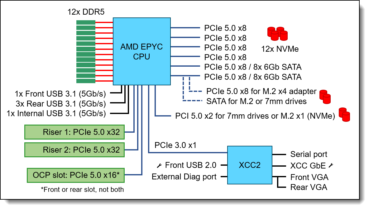
Figure 3. SR655 V3 (2U 1S) system architectural block diagram
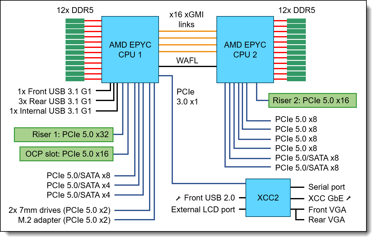
Figure 4. SR645 V3 (1U 2S) system architectural block diagram
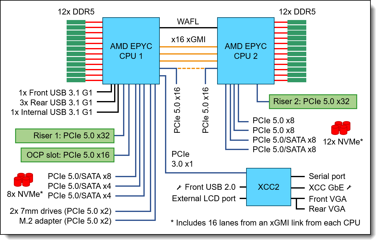
Figure 5. SR665 V3 (2U 2S) system architectural block diagram
The following figure show the architecture of the AMD EPYC 9654 processor: Genoa (16-96 cores) up to 12 CCDs per processor, 8 Zen4 cores per CCD,1MB L2 cache per core, 8 cores share 32MB L3 cache.
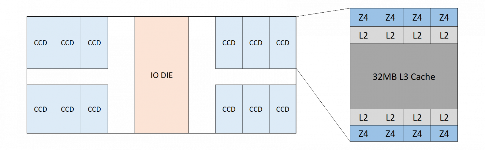
Figure 6. 4th Gen AMD EPYC 9654 (Genoa) Processor
The following figure show the architecture of the AMD EPYC 9684X processor. GenoaX (16-96 cores) up to 12 CCDs per processor, 8 Zen4 cores per CCD,1MB L2 cache per core, 8 cores share 32MB L3 cache with 64MB additional layered above (96MB total).
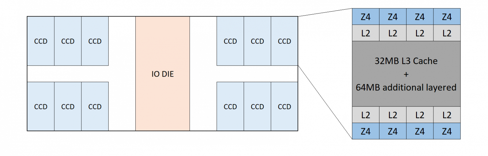
Figure 7. 4th Gen AMD EPYC 9684X (Genoa-X) Processor
The following figure show the architecture of the AMD EPYC 9754 processor. Bergamo (112-128 cores) up to 8 CCDs per processor, 2CCX per CCD, 8 Z4c cores per CCX,1MB L2 cache per core,16 MB L3 cache per CCX.
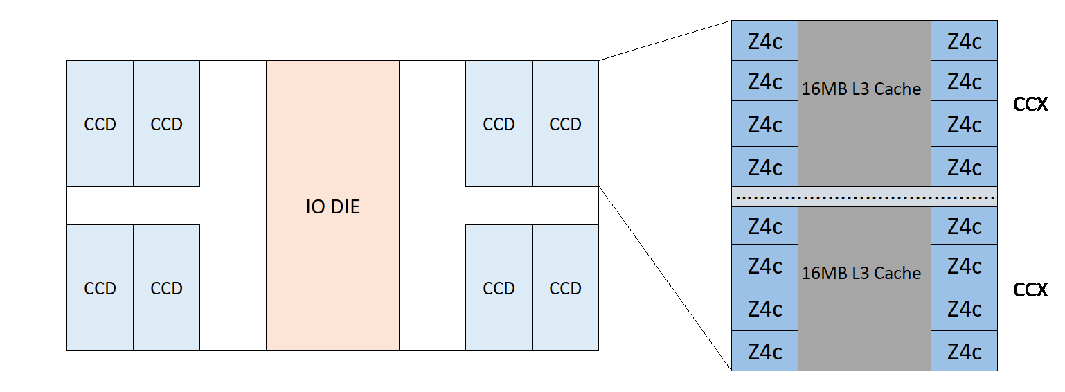
Figure 8. 4th Gen AMD EPYC “Bergamo 9754” Processor
The following table shows the architectural geometry of the 4th Gen EPYC processor including the core cache die (CCD), core complex (CCX) and cores per CCX for each processor. The NUMA Nodes per Socket (NPSx) options for each processor are also listed.
The following table shows EPYC Gen 4 CPU allowed maximum and minimum configurable TDP values.
Note: If the cTDP setting is set outside the limits that are supported by the installed CPU SKU, the cTDP value will automatically be limited to the minimum or maximum supported value.
References
See these links for more information:
- ThinkSystem SR635 V3 product guide
https://lenovopress.lenovo.com/lp1609-thinksystem-sr635-v3-server - ThinkSystem SR655 V3 product guide
https://lenovopress.lenovo.com/lp1610-thinksystem-sr655-v3-server - ThinkSystem SR645 V3 product guide
https://lenovopress.lenovo.com/lp1607-thinksystem-sr645-v3-server - ThinkSystem SR665 V3 product guide
https://lenovopress.lenovo.com/lp1608-thinksystem-sr665-v3-server - Tuning UEFI Settings for Performance and Energy Efficiency on AMD Processor-Based ThinkSystem Servers
https://lenovopress.lenovo.com/lp1267-tuning-uefi-settings-for-performance-and-energy-efficiency-on-amd-servers - AMD white paper: 4th Gen AMD EPYC Processor Architecture
https://www.amd.com/system/files/documents/4th-gen-epyc-processor-architecture-white-paper.pdf - Lenovo performance paper: Balanced Memory Configurations with 4th Gen AMD EPYC Processors
https://lenovopress.lenovo.com/lp1702-balanced-memory-configurations-with-4th-generation-amd-epyc-processors - Lenovo performance paper: Configuring AMD xGMI Links on the Lenovo ThinkSystem SR665 V3 Server
https://lenovopress.lenovo.com/lp1852-configuring-amd-xgmi-links-on-thinksystem-sr665-v3 - Lenovo XClarity Essentials OneCLI
https://support.lenovo.com/us/en/solutions/ht116433-lenovo-xclarity-essentials-onecli-onecli - Lenovo XClarity Controller REST API reference
https://pubs.lenovo.com/xcc-restapi/ - Lenovo Capacity Planner (LCP)
https://support.lenovo.com/us/en/solutions/ht504651-lenovo-capacity-planner-lcp
Author
Peter Xu is a Systems Performance Verification Engineer in the Lenovo Infrastructure Solutions Group Performance Laboratory in Morrisville, NC, USA. His current role includes CPU, Memory, and PCIe subsystem analysis and performance validation against functional specifications and vendor targets. Peter holds a Bachelor of Electronic and Information Engineering and a Master of Electronic Science and Technology, both from Hangzhou Dianzi University.
Trademarks
Lenovo and the Lenovo logo are trademarks or registered trademarks of Lenovo in the United States, other countries, or both. A current list of Lenovo trademarks is available on the Web at https://www.lenovo.com/us/en/legal/copytrade/.
The following terms are trademarks of Lenovo in the United States, other countries, or both:
Lenovo®
ThinkSystem®
XClarity®
The following terms are trademarks of other companies:
AMD, AMD EPYC™, and Infinity Fabric™ are trademarks of Advanced Micro Devices, Inc.
Intel®, the Intel logo and Xeon® are trademarks of Intel Corporation or its subsidiaries.
Microsoft®, Windows Server®, and Windows® are trademarks of Microsoft Corporation in the United States, other countries, or both.
SPECjbb® is a trademark of the Standard Performance Evaluation Corporation (SPEC).
NPS® is a trademark of IBM in the United States, other countries, or both.
Other company, product, or service names may be trademarks or service marks of others.
Configure and Buy
Please select a locale
Full Change History
Course Detail
Employees Only Content
The content in this document with a is only visible to employees who are logged in. Logon using your Lenovo ITcode and password via Lenovo single-signon (SSO).
The author of the document has determined that this content is classified as Lenovo Internal and should not be normally be made available to people who are not employees or contractors. This includes partners, customers, and competitors. The reasons may vary and you should reach out to the authors of the document for clarification, if needed. Be cautious about sharing this content with others as it may contain sensitive information.
Any visitor to the Lenovo Press web site who is not logged on will not be able to see this employee-only content. This content is excluded from search engine indexes and will not appear in any search results.
For all users, including logged-in employees, this employee-only content does not appear in the PDF version of this document.
This functionality is cookie based. The web site will normally remember your login state between browser sessions, however, if you clear cookies at the end of a session or work in an Incognito/Private browser window, then you will need to log in each time.
If you have any questions about this feature of the Lenovo Press web, please email David Watts at dwatts@lenovo.com.


