

Top
Author
Updated
15 Jul 2026Form Number
LP1601PDF size
196 pages, 22.5 MBSubscribed to LP1601.
Thank you for your feedback.
Download PDF
* Only available in selected markets
Table of Contents
- Introduction
- Did you know?
- Key features
- Performance benchmarks
- Comparing the SR650 V3 to the SR650 V2
- Components and connectors
- System architecture
- Standard specifications
- Top Choice
- Models
- Processors
- Memory options
- Internal storage
- Controllers for internal storage
- Internal drive options
- Internal backup units
- Optical drives
- I/O expansion
- Network adapters
- GPU adapters
- Fibre Channel host bus adapters
- SAS adapters for external storage
- Cooling
- Power supplies
- Systems management
- Security
- Rack installation
- Operating system support
- Physical and electrical specifications
- Operating environment
- Water infrastructure for the Lenovo Neptune Processor DWC Module
- Warranty upgrades and post-warranty support
- Services
- Lenovo TruScale
- Regulatory compliance
- External drive enclosures
- External storage systems
- External backup units
- Fibre Channel SAN switches
- Uninterruptible power supply units
- Power distribution units
- Rack cabinets
- KVM console options
- Lenovo Financial Services
- Seller training courses
- Related publications and links
- Related product families
- Trademarks
Abstract
The Lenovo ThinkSystem SR650 V3 is an ideal 2-socket 2U rack server for small businesses up to large enterprises that need industry-leading reliability, management, and security, as well as maximizing performance and flexibility for future growth. The SR650 V3 is designed to handle a wide range of workloads, such as databases, virtualization and cloud computing, virtual desktop infrastructure (VDI), infrastructure security, systems management, enterprise applications, collaboration/email, streaming media, web, and HPC.
This product guide provides essential pre-sales information to understand the ThinkSystem SR650 V3 server, its key features and specifications, components and options, and configuration guidelines. This guide is intended for technical specialists, sales specialists, sales engineers, IT architects, and other IT professionals who want to learn more about the SR650 V3 and consider its use in IT solutions.

Pushing the boundaries of authentication technology
Meeting growing demand for innovative digital authentication solutions with Lenovo ThinkSystem SR650 V3 servers powered by 4th Gen Intel® Xeon® Scalable processors.


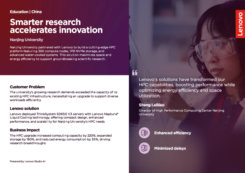
Smarter research accelerates innovation
Nanjing University embraced Lenovo's ThinkSystem SD650 V3 water-cooled HPC solution to create a high-performance computing platform. With 360 compute nodes, 1PB NVMe all-flash storage, and a compact design maximizing space and energy efficiency, they are driving scientific breakthroughs while reducing operational costs.
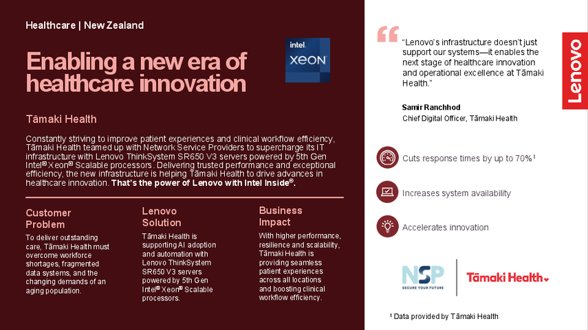
Enabling healthcare innovation
Constantly striving to improve patient experiences and clinical workflow efficiency, Tāmaki Health teamed up with Network Service Providers to supercharge its IT infrastructure with Lenovo ThinkSystem SR650 V3 servers powered by 5th Gen Intel® Xeon® Scalable processors—helping to drive advances in healthcare innovation.
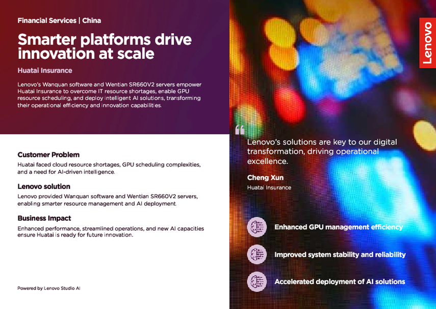
Smarter AI Infrastructure Powers Huatai Insurance’s Enterprise Transformation
Lenovo’s cutting-edge solutions, including the Lenovo Wanquan software and Wentian SR660V2 servers, empower Huatai Insurance to transform their IT infrastructure. With smarter resource management, Huatai accelerates business intelligence, enhances cloud platforms, and creates seamless enterprise-wide operations.
Racing towards faster, smarter, more sustainable sport
To bring the exhilaration of race day to more than 820 million fans all over the world, F1® relies on Lenovo technology. From the track to the broadcast and digital products, Lenovo delivers devices, solutions, and the IT infrastructure that can withstand the breakneck pace of innovation in the world of motorsport while helping F1 stay on track to meet its sustainability goals.

The Sandwell Colleges upgrade their IT facilities with data center, endpoint, and VR headset solutions from Lenovo, helping to give students the best possible learning experience and prepare them for the workplace.
A state-of-the-art new medical center in Riyadh, MedTown Hospital looked for a technology partner to build out its data center to support 24/7/365 operations. With Lenovo, the hospital has a stable, scalable IT infrastructure backed by round-the-clock support services.
1 of 19 case studies
Change History
Changes in the July 15, 2026 update:
- Added the Performance benchmarks section
Introduction
The Lenovo ThinkSystem SR650 V3 is an ideal 2-socket 2U rack server for small businesses up to large enterprises that need industry-leading reliability, management, and security, as well as maximizing performance and flexibility for future growth. The SR650 V3 is based on the new 5th generation Intel Xeon Scalable processor family (formerly codenamed "Emerald Rapids").
The SR650 V3 is designed to handle a wide range of workloads, such as databases, virtualization and cloud computing, virtual desktop infrastructure (VDI), infrastructure security, systems management, enterprise applications, collaboration/email, streaming media, web, and HPC.
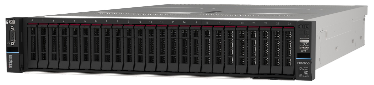
Figure 1. Lenovo ThinkSystem SR650 V3 with 2.5-inch front drive bays (3.5-inch drive configurations also available)
Did you know?
The SR650 V3 server has been designed to take advantage of the features of the 5th generation Intel Xeon Scalable processors, such as the full performance of 385W 64-core processors, support for 5600 MHz memory and PCIe Gen 5.0 support. The SR650 V3 is a very configuration-rich offering, supporting more than 30 different drive bay configurations in the front, middle and rear of the server and 5 different slot configurations at the rear of the server. This level of flexibility ensures that you can configure the server to meet the needs of your workload.
Key features
Combining performance and flexibility, the SR650 V3 server is a great choice for enterprises of all sizes. The server offers a broad selection of drive and slot configurations and offers numerous high performance features. Outstanding reliability, availability, and serviceability (RAS) and high-efficiency design can improve your business environment and can help save operational costs.
Scalability and performance
The SR650 V3 offers numerous features to boost performance, improve scalability and reduce costs:
- Supports one or two fifth-generation Intel Xeon Processor Scalable processors
- Up to 64 cores and 128 threads
- Core speeds of up to 3.9 GHz
- TDP ratings of up to 385 W
- Supports one or two fourth-generation Intel Xeon Processor Scalable processors
- Up to 60 cores and 120 threads
- Core speeds of up to 3.7 GHz
- TDP ratings of up to 350 W
- Support for DDR5 memory DIMMs to maximize the performance of the memory subsystem:
- Up to 32 DDR5 memory DIMMs, 16 DIMMs per processor
- 8 memory channels per processor (2 DIMMs per channel)
- Supports 1 DIMM per channel operating at 5600 MHz (5th Gen processors) or 4800 MHz (4th Gen processors)
- Supports 2 DIMMs per channel operating at 4800 MHz (5th Gen processors) or 4400 MHz (4th Gen processors)
- Using 256GB 3DS RDIMMs, the server supports up to 8TB of system memory
- Supports the new Intel Optane Persistent Memory 300 Series for advanced in-memory database applications, dense-virtualization; up to 16 PMem Modules can be installed in conjunction with regular system memory.
- Supports up to eight single-width GPUs or three double-wide GPUs, for substantial processing power in a 2U system.
- The server is Compute Express Linsk (CXL) v1.1 Ready. With CXL 1.1 for next-generation workloads, you can reduce compute latency in the data center and lower TCO. CXL is a protocol that runs across the standard PCIe physical layer and can support both standard PCIe devices as well as CXL devices on the same link.
- Supports up to 40x 2.5-inch drive bays, by using combinations of front-accessible (up to 24 bays), mid bays (8 bays) and rear-accessible (8 bays).
- Supports 20x 3.5-inch drive bays for lower-cost high-capacity HDD storage. 2.5-inch and 3.5-inch drive bays can be mixed if desired.
- Supports 36x NVMe drives without oversubscription of PCIe lanes (1:1 connectivity). The use of NVMe drives maximizes drive I/O performance, in terms of throughput and latency.
- Supports 14x SATA drives using the onboard SATA controller (no additional adapter needed), enabling lower cost, high capacity storage solution for cold or archival storage workloads.
- Supports high-speed RAID controllers from Broadcom providing 12 Gb SAS connectivity to the drive backplanes. A variety of PCIe 3.0 and PCIe 4.0 RAID adapters are available.
- Supports up to two externally accessible 7mm hot-swap drives for operating system boot functions. Optional RAID-0 or RAID-1.
- Supports M.2 drives for convenient operating system boot functions. Available M.2 adapters support either one M.2 drive or two M.2 drives. Optional RAID-0 or RAID-1.
- Up to 12x PCIe slots (10x rear, 2x front), plus a slot dedicated to an OCP 3.0 adapter. 2.5-inch drive configurations also support an additional internal bay for a cabled RAID adapter or HBA.
- The server has a dedicated industry-standard OCP 3.0 small form factor (SFF) slot, supporting a variety of Ethernet network adapters. A simple-swap mechanism with a thumbscrew and pull-tab enables tool-less installation and removal of the adapter. The adapter supports shared BMC network sideband connectivity to enable out-of-band systems management.
- The server offers PCI Express 5.0 I/O expansion capabilities that doubles the theoretical maximum bandwidth of PCIe 4.0 (32GT/s in each direction for PCIe Gen 5, compared to 16 GT/s with PCIe Gen 4 and 8 GT/s with PCIe Gen 3). A PCIe 5.0 x16 slot provides 128 GB/s bandwidth, enough to support a dual-port 200GbE network connection.
Availability and serviceability
The SR650 V3 provides many features to simplify serviceability and increase system uptime:
- Designed to run 24 hours a day, 7 days a week
- The server offers Single Device Data Correction (SDDC, also known as Chipkill), Adaptive Double-Device Data Correction (ADDDC, also known as Redundant Bit Steering or RBS), and memory mirroring for redundancy in the event of a non-correctable memory failure. Note: ADDDC in not supported with 9x4 RDIMMs.
- The server offers hot-swap drives, supporting RAID redundancy for data protection and greater system uptime.
- Available M.2 adapters support RAID-1 (using Intel VROC) which can enable two SATA or two NVMe M.2 drives to be configured as a redundant pair.
- The server has up to two hot-swap redundant power supplies and up to six hot-swap redundant fans to provide availability for business-critical applications.
- Optional front-accessible slots and drives so that most major components and cables (except power) are located at the front of the server
- The light path diagnostics feature uses LEDs to lead the technician to failed (or failing) components, which simplifies servicing, speeds up problem resolution, and helps improve system availability.
- Solid-state drives (SSDs) offer more reliability and performance than traditional mechanical HDDs for greater uptime.
- Proactive Platform Alerts (including PFA and SMART alerts): Processors, voltage regulators, memory, internal storage (SAS/SATA HDDs and SSDs, NVMe SSDs, M.2 storage), fans, power supplies, RAID controllers, server ambient and subcomponent temperatures. Alerts can be surfaced through the XClarity Controller to managers such as Lenovo XClarity One, VMware vCenter, and Microsoft System Center. These proactive alerts let you take appropriate actions in advance of possible failure, thereby increasing server uptime and application availability.
- The built-in XClarity Controller continuously monitors system parameters, triggers alerts, and performs recovery actions in case of failures to minimize downtime.
- Built-in diagnostics in UEFI, using Lenovo XClarity Provisioning Manager, speed up troubleshooting tasks to reduce service time.
- Lenovo XClarity Provisioning Manager supports diagnostics and can save service data to a USB key drive or remote CIFS share folder for troubleshooting and reduce service time.
- Auto restart in the event of a momentary loss of AC power (based on power policy setting in the XClarity Controller service processor)
- Offers a diagnostics port on the front of the server to allow you to attach an external diagnostics handset for enhanced systems management capabilities.
- Support for the XClarity Mobile app running on a supported smartphone or tablet and connected to the server through the service-enabled USB port, enables additional local systems management functions.
- Three-year or one-year customer-replaceable unit and onsite limited warranty (varies by geography), 9 x 5 next business day. Optional service upgrades are available.
Manageability and security
Systems management features simplify local and remote management of the SR650 V3:
- The server includes XClarity Controller 2 (XCC2) to monitor server availability. Optional upgrade to XCC Platinum to provide remote control (keyboard video mouse) functions, support for the mounting of remote media files (ISO and IMG image files), boot capture, power capping and new XCC2 Platinum features. New XCC2 Platinum features include System Guard, new security modes including a CNSA-compliant mode, a FIPS 140-3-compliant mode and enhanced NIST 800-193 support, and a new Neighbor Group feature.
- Dedicated Ethernet port at the rear of the server for remote management (BMC management).
- Lenovo XClarity One offers comprehensive hardware management tools that help to increase uptime, reduce costs and improve productivity through advanced server management capabilities.
- UEFI-based Lenovo XClarity Provisioning Manager, accessible from F1 during boot, provides system inventory information, graphical UEFI Setup, platform update function, RAID Setup wizard, operating system installation function, and diagnostic functions.
- Support for Lenovo XClarity Energy Manager, which captures real-time power and temperature data from the server and provides automated controls to lower energy costs.
- An integrated industry-standard Unified Extensible Firmware Interface (UEFI) enables improved setup, configuration, and updates, and simplifies error handling.
- Support for industry standard management protocols, IPMI 2.0, SNMP 3.0, Redfish REST API, serial console via IPMI
- An integrated hardware Trusted Platform Module (TPM) supporting TPM 2.0 enables advanced cryptographic functionality, such as digital signatures and remote attestation.
- Administrator and power-on passwords help protect from unauthorized access to the server.
- Supports Secure Boot to ensure only a digitally signed operating system can be used. Supported with HDDs and SSDs, as well as 7mm and M.2 drives.
- Industry-standard Advanced Encryption Standard (AES) NI support for faster, stronger encryption.
- Intel Execute Disable Bit functionality can prevent certain classes of malicious buffer overflow attacks when combined with a supported operating system.
- Intel Trusted Execution Technology provides enhanced security through hardware-based resistance to malicious software attacks, allowing an application to run in its own isolated space, protected from all other software running on a system.
- Additional physical security features are an available chassis intrusion switch and available lockable front bezel.
Energy efficiency
The SR650 V3 offers the following energy-efficiency features to save energy, reduce operational costs, and increase energy availability:
- The server supports an advanced direct-water cooling (DWC) capability with the Lenovo Neptune Processor DWC Module, where heat from the processors is removed from the rack and the data center using an open loop and coolant distribution units, resulting in lower energy costs
- Energy-efficient system board components help lower operational costs.
- High-efficiency power supplies with 80 PLUS Platinum and Titanium certifications
- Solid-state drives (SSDs) consume as much as 80% less power than traditional spinning 2.5-inch HDDs.
- The server uses hexagonal ventilation holes, which can be grouped more densely than round holes, providing more efficient airflow through the system and thus keeping your system cooler.
- Optional Lenovo XClarity Energy Manager provides advanced data center power notification, analysis, and policy-based management to help achieve lower heat output and reduced cooling needs.
Performance benchmarks
At Lenovo, we know customers care most about how their workloads perform in real-world environments, which is why we carefully tune our server hardware, firmware, and drivers to help deliver strong benchmark results that reflect practical business needs. The goal is simple: to help customers run their critical applications more efficiently and achieve better outcomes.
The following table lists the current world record performance benchmarks that Lenovo performance engineers have achieved on the SR650 V3. This reinforces that the server is an excellent choice for a server to run wide range of application workloads.
The SR650 V3 has a total of 11 current performance benchmark world records.
Results referenced are current as of July 1, 2026.
| Benchmark | Sub-benchmark | Benchmark metric | Current world records | Lenovo result | Link |
|---|---|---|---|---|---|
| TPCx-AI v2 | - | AIUCpm and USD per AIUCpm | 2 | Best 2P performance @ SF3 and Best 2P price/performance @ SF3 | TPCx-AI link |
| MLperf Inference v4.1 Closed Datacenter Division | Medical Imaging, 99.0% Accuracy, Offline Scenario (3d-unet) | Samples/s | 1 | #1 Performance for Available configurations with 3 GPUs | MLperf link |
| MLperf Inference v4.1 Closed Datacenter Division | Natural language processing, 99.0% Accuracy, Offline Scenario (Bert) | Samples/s | 1 | #1 Performance for Available configurations with 3 GPUs | MLperf link |
| MLperf Inference v4.1 Closed Datacenter Division | Natural language processing, 99.0% Accuracy, Server Scenario (Bert) | Queries/s | 1 | #1 Performance for Available configurations with 3 GPUs | MLperf link |
| MLperf Inference v4.1 Closed Datacenter Division | LLM, 99.0% Accuracy, Offline Scenario (GPT-J) | Tokens/s | 1 | #1 Performance for Available configurations with 3 GPUs | MLperf link |
| MLperf Inference v4.1 Closed Datacenter Division | LLM, 99.0% Accuracy, Server Scenario (GPT-J) | Tokens/s | 1 | #1 Performance for Available configurations with 3 GPUs | MLperf link |
| MLperf Inference v4.1 Closed Datacenter Division | Image classification, 99% Accuracy, Offline Scenario (ResNet50-v1.5) | Samples/s | 1 | #1 Performance for Available configurations with 3 GPUs | MLperf link |
| MLperf Inference v4.1 Closed Datacenter Division | Image classification, 99% Accuracy, Server Scenario (ResNet50-v1.5) | Queries/s | 1 | #1 Performance for Available configurations with 3 GPUs | MLperf link |
| MLperf Inference v4.1 Closed Datacenter Division | Object Detection, 99% Accuracy, Offline Scenario (RetinaNet) | Samples/s | 1 | #1 Performance for Available configurations with 3 GPUs | MLperf link |
| MLperf Inference v4.1 Closed Datacenter Division | Object Detection, 99% Accuracy, Server Scenario (RetinaNet) | Queries/s | 1 | #1 Performance for Available configurations with 3 GPUs | MLperf link |
See the complete list of current world records in the Lenovo Press article Performance Benchmark World Record Summary for Lenovo ThinkSystem Servers.
The Lenovo Server Performance Team also publishes reports on key performance world records at the time the world record is announced. See all published Performance Benchmark Reports.
Comparing the SR650 V3 to the SR650 V2
The ThinkSystem SR650 V3 improves on the previous generation SR650 V2, as summarized in the following table.
Components and connectors
The following figure shows the front of the SR650 V3.
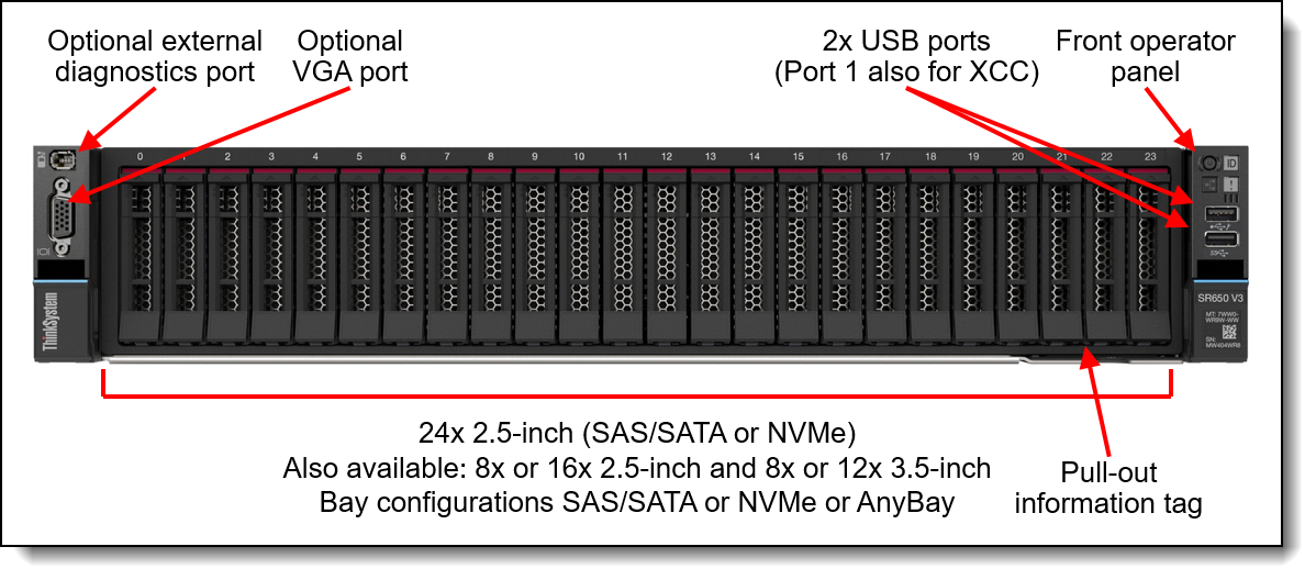
Figure 2. Front view of the ThinkSystem SR650 V3 with 2.5-inch drive bays
For details on the front ports, including the optional front VGA port and optional external diagnostic port, see the Local management section.
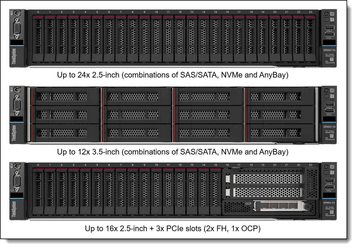
The following figure shows the front configurations of the SR650 V3. The server supports either 2.5-inch hot-swap drives (8, 16 or 24 drive bays) or 3.5-inch hot-swap drives (8 or 12 bays) at the front. The server also supports three front PCIe slots (2 full-height, 1 OCP) in addition to 16x 2.5-inch drive bays.
The following figure shows the components visible from the rear of the server. The figure shows one configuration, with eight PCIe slots, however there are additional rear configurations which include 3.5-inch drive bays, 2.5-inch drive bays, or 7mm drive bays.
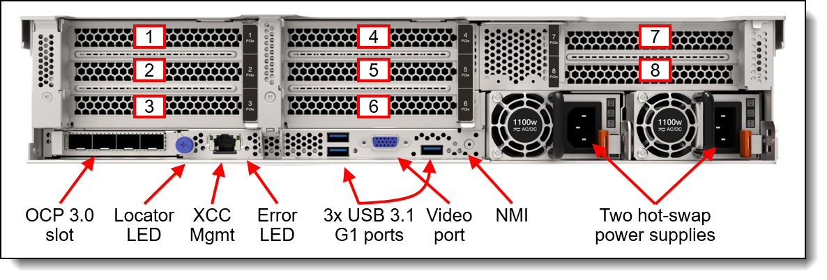
Figure 4. Rear view of the ThinkSystem SR650 V3 (configuration with eight PCIe slots)

Standard specifications
The following table lists the standard specifications.
| Components | Specification |
|---|---|
| Machine types | 7D75 - 1 year warranty 7D76 - 3 year warranty |
| Form factor | 2U rack |
| Processor | One or two 5th Gen Intel Xeon Scalable processors (formerly codenamed "Emerald Rapids"), or one or two 4th Gen Intel Xeon Scalable processors (formerly codenamed "Sapphire Rapids"). Supports processors up to 64 cores, core speeds of up to 3.9 GHz, and TDP ratings of up to 385 W. |
| Chipset | Intel C741 "Emmitsburg" chipset, part of the platform codenamed "Eagle Stream" |
| Memory | 32 DIMM slots with two processors (16 DIMM slots per processor). Each processor has 8 memory channels, with 2 DIMMs per channel (DPC). Lenovo TruDDR5 RDIMMs, 9x4 RDIMMs, and 3DS RDIMMs are supported. DIMMs operate at up to 5600 MHz at 1 DPC and up to 4800 MHz at 2 DPC. |
| Persistent memory | No support. Supports up to 16x Intel Optane Persistent Memory 300 Series modules (8 per processor) installed in the DIMM slots. Persistent memory (Pmem) is installed in combination with system memory DIMMs. |
| Memory maximum | With RDIMMs: Up to 8TB by using 32x 256GB 3DS RDIMMs With Persistent Memory: Up to 12TB by using 16x 256GB 3DS RDIMMs and 16x 512GB Pmem modules |
| Memory protection | ECC, SDDC (for x4-based memory DIMMs), ADDDC (for x4-based memory DIMMs excluding 9x4 RDIMMs, requires Platinum or Gold processors), and memory mirroring. |
| Disk drive bays |
Up to 20x 3.5-inch or 40x 2.5-inch hot-swap drive bays:
The server also supports these drives for OS boot or drive storage:
See Supported drive bay combinations for details. |
| Maximum internal storage |
|
| Storage controller |
|
| Optical drive bays | No internal optical drive |
| Tape drive bays | No internal backup drive |
| Network interfaces | Dedicated OCP 3.0 SFF slot with PCIe 5.0 x16 host interface. Supports a variety of 2-port and 4-port adapters with 1, 10, 25 or 100 GbE network connectivity. One port can optionally be shared with the XClarity Controller 2 (XCC2) management processor for Wake-on-LAN and NC-SI support. |
| PCIe slots |
Up to 12x PCIe slots (10x rear, 2x front), plus a slot dedicated to an OCP 3.0 adapter. 2.5-inch drive configurations also support an additional internal bay for a cabled RAID adapter or HBA. Rear: Up to 10x PCIe slots, plus a slot dedicated to the OCP adapter. Slot are either PCIe 5.0 or 4.0 depending on riser selection and rear drive bay selection. The use of some slots requires two processors. Slots are configured using three riser cards. Riser 1 (slots 1-3) and Riser 2 (slots 4-6) are installed in slots in the system board, Riser 3 (slots 7-8) and Riser 4 (9-10) are cabled to ports on the system board. A variety of riser cards are available. See the I/O expansion for details. Front: The server also supports slots at the front of the server (configurations with up to 16 drive bays): 2x PCIe x16 full-height half-length slots, plus 1x OCP 3.0 slot Internal: For 2.5-inch front drive configurations, the server supports the installation of a RAID adapter or HBA in a dedicated area that does not consume any of the PCIe slots. |
| GPU support | Supports up to 8x single-wide GPUs or up to 3x double-wide GPUs |
| Ports |
Front: 1x USB 3.2 G1 (5 Gb/s) port, 1x USB 2.0 port (also for XCC local management), External diagnostics port, optional VGA port. Rear: 3x USB 3.2 G1 (5 Gb/s) ports, 1x VGA video port, 1x RJ-45 1GbE systems management port for XCC remote management. Optional DB-9 COM serial port (installs in a PCIe slot). Internal: 1x USB 3.2 G1 (5 Gb/s) connector for operating system or license key purposes |
| Cooling | 6x (with two processors installed) or 5x (with one processor installed) single-rotor or dual-rotor hot swap 60 mm fans, configuration dependent. Fans are N+1 redundant, tolerating a single-rotor failure. One fan integrated in each power supply. For customers with water infrastructure in their data center, the SR650 V3 also supports open-loop water cooling for efficient heat removal. |
| Power supply | Up to two hot-swap redundant AC power supplies, 80 PLUS Platinum or 80 PLUS Titanium certification. 750 W, 1100 W, 1800 W, 2400 W and 2600W AC options, supporting 220 V AC. 750 W and 1100 W options also support 110V input supply. In China only, all power supply options support 240 V DC. Also available is a 1100W power supply with a -48V DC input. |
| Video | Embedded graphics with 16 MB memory with 2D hardware accelerator, integrated into the XClarity Controller 2 management controller. Maximum resolution is 1920x1200 32bpp at 60Hz. |
| Hot-swap parts | Drives, power supplies, and fans. |
| Systems management | Operator panel with status LEDs. Optional External Diagnostics Handset with LCD display. Models with 8x or 16x 2.5-inch front drive bays can optionally support an Integrated Diagnostics Panel. XClarity Controller 2 (XCC2) embedded management controller, XClarity One centralized infrastructure delivery, XClarity Integrator plugins, and XClarity Energy Manager centralized server power management. Optional XClarity Controller Platinum to enable remote control and other functions. |
| Security features | Chassis intrusion switch, Power-on password, administrator's password, Root of Trust module supporting TPM 2.0 and Platform Firmware Resiliency (PFR). Optional lockable front security bezel. |
| Operating systems supported | Microsoft Windows Server, Microsoft Windows 10 & 11, Red Hat Enterprise Linux, SUSE Linux Enterprise Server, VMware ESXi, Ubuntu Server. See the Operating system support section for specifics. |
| Limited warranty | Three-year or one-year (model dependent) customer-replaceable unit and onsite limited warranty with 9x5 next business day (NBD). |
| Service and support | Optional service upgrades are available through Lenovo Services: 4-hour or 2-hour response time, 6-hour fix time, 1-year or 2-year warranty extension, software support for Lenovo hardware and some third-party applications. |
| Dimensions | Width: 445 mm (17.5 in.), height: 87 mm (3.4 in.), depth: 766 mm (30.1 in.). See Physical and electrical specifications for details. |
| Weight | Maximum: 38.8 kg (85.5 lb) |
Top Choice
Lenovo offers two “quick-ship” programs to make it easy for our customers to get quick delivery of our offerings:
- Top Choice Express (TCE): A Configure-to-Order (CTO) model that uses a "best of" subset of components. It allows for customization while maintaining significantly faster lead times than standard CTO.
Top Choice Express (TCE) is the way to get custom configurations as quickly as possible. It allows DCSC configurator users to configure systems in CTO Mode, selecting the required hardware components while still benefiting from faster turnaround than traditional CTO. These configurations are built and fully integrated by Lenovo Manufacturing, with simple configuration steps, instant pricing, and quicker delivery.
To see which components are TCE, check the TCE column in the various component tables in this product guide. Green cells mean that the component is enabled for ordering with Top Choice Express in all regions world-wide. Orange cells with the symbol mean that the component is enable for Top Choice Express in only some regions. Mouse over or tap on the cell to see which regions have it enabled for TCE.
Note: Top Choice Express is for configure-to-order builds only, not for standalone option part numbers.
- Top Choice Stock (TCS): Pre-built, fixed-configuration units held in distribution. They are the "Ready-to-Ship" inventory options for customers who need a server quickly.
Top Choice Stock (TCS) is used in Preconfigured Mode, starting from a standard pre‑built configuration and adding option components as needed. Systems are assembled and fulfilled by Lenovo partners, enabling quick order processing and fast shipment through distribution. This path supports rapid delivery while maintaining flexibility through add‑on options. For details of TCS models, see the Preconfigured Models section.
Note: Ship dates are estimates only; actual ship times may vary based on platform and component availability, order processing, logistics, and external factors beyond Lenovo’s control. Lenovo is not liable for delays.
Models
ThinkSystem SR650 V3 models can be configured by using the Lenovo Data Center Solution Configurator (DCSC).
Topics in this section:
- CTO models
- CTO models for Windows 10 and Windows 11
- CTO models for NVIDIA Bluefield-2 SmartNIC DPUs
- Base feature codes
- Preconfigured models
CTO models
ThinkSystem SR650 V3 models can be configured by using the Lenovo Data Center Solution Configurator (DCSC).
Configure-to-order (CTO) models are used to create models with factory-integrated server customizations. For CTO models, two types of base CTO models are available for the SR650 V3 as listed in the columns in the following table:
- General purpose base CTO models are for general business (non-HPC) and is selectable by choosing General Purpose mode in DCSC.
- AI and HPC base models are intended for Artificial Intelligence (AI) and High Performance Computing (HPC) configurations and solutions are enabled using the AI & HPC Hardware - ThinkSystem Hardware mode in DCSC. These configurations, along with Lenovo EveryScale Solutions, can also be built using System x and Cluster Solutions Configurator (x-config). Tip: Some HPC and AI models are not listed in DCSC and can only be configured in x-config.
"For AI" models: The base CTO models listed in the table with "for AI" in the names are the only base models that support high-performance GPUs and accelerators (Controlled GPUs). These models are classified under US Government ECCN regulations and have limited market and customer availability. All other base models do not support high-performance GPUs.
Preconfigured server models may also be available for the SR650 V3, however these are region-specific; that is, each region may define their own server models, and not all server models are available in every region.
The following table lists the base CTO models of the ThinkSystem SR650 V3 server.
CTO models for Windows 10 and Windows 11
The SR650 V3 can run Windows 10 and Windows 11, however only a subset of adapters and drives can be installed. For ease of configuration, the following Base CTO models have been announced to assist building a configuration that can be used with the client operating systems. For more information, see the Windows 10 and Windows 11 section.
CTO models for NVIDIA Bluefield-2 SmartNIC DPUs
The SR650 V3 supports the new VMware vSphere Distributed Services Engine (DSE) using the NVIDIA Bluefield-2 SmartNIC Data Processing Unit (DPU). This solution improves the performance of VMware vSphere by offloading tasks from server CPUs to the DPU thereby making data center applications more efficient.
When configuring VMware vSphere Distributed Services Engine using NVIDIA BlueField-2 DPUs, you will need to build the server in the DCSC configurator starting from the DPU-specific CTO models listed in the following table.
BlueField-3 support: These CTO models are not required for BlueField-3 DPUs.
For more information, see the DPU adapter section.
Base feature codes
Models of the SR650 V3 are defined based on whether the server has 2.5-inch drive bays at the front (called the 2.5-inch chassis) or whether it has 3.5-inch drive bays at the front (called the 3.5-inch chassis). For models, the feature codes for these chassis bases are as listed in the following table.
Preconfigured models
The following tables list the available preconfigured models, grouped by region.
- Models for Asia Pacific region
- Models for Australia and New Zealand
- Models for Brazil
- Models for China
- Models for EMEA region
- Models for Hong Kong, Taiwan, Korea (HTK)
- Models for India
- Models for Japan
- Models for Latin American countries (except Brazil)
- Models for USA and Canada
Refer to the Specifications section for information about standard features of the server.
Common to all models:
- Power supplies are Platinum unless otherwise stated
- All models include a Toolless Slide Rail Kit
Models for Asia Pacific region
The following table lists the models for the Asia Pacific region: Australia, Bangladesh, Brunei, Hong Kong, India, Japan, Korea, Sri Lanka, Malaysia, New Zealand, Philippines, Singapore, Thailand, Taiwan, Vietnam
† Processor description: Processor model, number of cores, thermal design power (TDP), core frequency
Models for Australia and New Zealand
AP models: Customers in Australia and New Zealand also have access to the Asia Pacific region models.
Common to all Australia and New Zealand models:
- All models include a Toolless Slide Rail Kit and Cable Management Arm
† Processor description: Processor model, number of cores, thermal design power (TDP), core frequency
Models for Brazil
† Processor description: Processor model, number of cores, thermal design power (TDP), core frequency
Models for China
† Processor description: Processor model, number of cores, thermal design power (TDP), core frequency
Models for EMEA region
† Processor description: Processor model, number of cores, thermal design power (TDP), core frequency
Models for Hong Kong, Taiwan, Korea (HTK)
AP models: Customers in Hong Kong, Taiwan, and Korea also have access to the Asia Pacific region models.
† Processor description: Processor model, number of cores, thermal design power (TDP), core frequency
Models for India
AP models: Customers in India also have access to the Asia Pacific region models.
† Processor description: Processor model, number of cores, thermal design power (TDP), core frequency
Models for Japan
AP models: Customers in Japan also have access to the Asia Pacific region models.
† Processor description: Processor model, number of cores, thermal design power (TDP), core frequency
Models for Latin American countries (except Brazil)
† Processor description: Processor model, number of cores, thermal design power (TDP), core frequency
Models for USA and Canada
† Processor description: Processor model, number of cores, thermal design power (TDP), core frequency
Processors
The SR650 V3 supports processors in either the 5th Gen Intel Xeon Scalable Processor family ("Emerald Rapids") or the 4th Gen Intel Xeon Scalable Processor family ("Sapphire Rapids"). The server supports one or two processors.
Topics in this section:
Processor options
All supported processors have the following characteristics:
- 8 DDR5 memory channels at 2 DIMMs per channel
- Up to 4 UPI links between processors at up to 20 GT/s
- Up to 80 PCIe 5.0 I/O lanes
The following table lists the 5th Gen processors that are currently supported by the SR650 V3. The table includes a Top Choice Express column; for CTO orders, select a TCE component for faster delivery. See the Top Choice section for more information.
* These processors are single-socket capable processors and are only available in configure-to-order builds or in preconfigured models. Not available as option part numbers.
The following table lists the 4th Gen processors that are currently supported by the SR650 V3.
* These processors are single-socket capable processors and are only available in configure-to-order builds or in preconfigured models. Not available as option part numbers.
Configuration notes:
- Processor options include a heatsink but do not include a system fan
- Single-processor configurations are not supported
Processor features
Processors supported by the SR650 V3 introduce new embedded accelerators to add even more processing capability:
- QuickAssist Technology (Intel QAT)
Help reduce system resource consumption by providing accelerated cryptography, key protection, and data compression with Intel QuickAssist Technology (Intel QAT). By offloading encryption and decryption, this built-in accelerator helps free up processor cores and helps systems serve a larger number of clients.
- Intel Dynamic Load Balancer (Intel DLB)
Improve the system performance related to handling network data on multi-core Intel Xeon Scalable processors. Intel Dynamic Load Balancer (Intel DLB) enables the efficient distribution of network processing across multiple CPU cores/threads and dynamically distributes network data across multiple CPU cores for processing as the system load varies. Intel DLB also restores the order of networking data packets processed simultaneously on CPU cores.
- Intel Data Streaming Accelerator (Intel DSA)
Drive high performance for storage, networking, and data-intensive workloads by improving streaming data movement and transformation operations. Intel Data Streaming Accelerator (Intel DSA) is designed to offload the most common data movement tasks that cause overhead in data center-scale deployments. Intel DSA helps speed up data movement across the CPU, memory, and caches, as well as all attached memory, storage, and network devices.
- Intel In-Memory Analytics Accelerator (Intel IAA)
Run database and analytics workloads faster, with potentially greater power efficiency. Intel In-Memory Analytics Accelerator (Intel IAA) increases query throughput and decreases the memory footprint for in-memory database and big data analytics workloads. Intel IAA is ideal for in-memory databases, open source databases and data stores like RocksDB, Redis, Cassandra, and MySQL.
- Intel Advanced Matrix Extensions (Intel AMX)
Intel Advanced Matrix Extensions (Intel AMX) is a built-in accelerator in all Silver, Gold, and Platinum processors that significantly improves deep learning training and inference. With Intel AMX, you can fine-tune deep learning models or train small to medium models in just minutes. Intel AMX offers discrete accelerator performance without added hardware and complexity.
The processors also support a separate and encrypted memory space, known as the SGX Enclave, for use by Intel Software Guard Extensions (SGX). The size of the SGX Enclave supported varies by processor model. Intel SGX offers hardware-based memory encryption that isolates specific application code and data in memory. It allows user-level code to allocate private regions of memory (enclaves) which are designed to be protected from processes running at higher privilege levels.
The following table summarizes the key features of all supported 5th Gen processors in the SR650 V3.
† The maximum single-core frequency at with the processor is capable of operating
* L3 cache is 1.875 MB per core or larger. Processors with a larger L3 cache per core are marked with an *
** Bronze 3508U aprocessor does not support Hyper-Threading Technology
‡ SKUs with a U suffix as well as some other SKUs have no UPI links and are are single-socket only
The following table summarizes the key features of all supported 4th Gen processors in the SR650 V3.
† The maximum single-core frequency at with the processor is capable of operating
* L3 cache is 1.875 MB per core or larger. Processors with a larger L3 cache per core are marked with an *
** Bronze 3408U processor does not support Hyper-Threading Technology
‡ SKUs with a U suffix as well as some other SKUs have no UPI links and are are single-socket only
Intel On Demand feature licensing
Intel On Demand is a licensing offering from Lenovo for certain 4th Gen and 5th Gen Intel Xeon Scalable processors that implements software-defined silicon (SDSi) features. The licenses allow customers to activate the embedded accelerators and to increase the SGX Enclave size in specific processor models as their workload and business needs change.
The available upgrades are the following:
- Up to 4x QuickAssist Technology (Intel QAT) accelerators
- Up to 4x Intel Dynamic Load Balancer (Intel DLB) accelerators
- Up to 4x Intel Data Streaming Accelerator (Intel DSA) accelerators
- Up to 4x Intel In-Memory Analytics Accelerator (Intel IAA) accelerators
- 512GB SGX Enclave, an encrypted memory space for use by Intel Software Guard Extensions (SGX)
See the Processor features section for a brief description of each accelerator and the SGX Enclave.
The following table lists the ordering information for the licenses. Accelerator licenses are bundled together based on the suitable workloads each would benefit with the additional accelerators.
Licenses can be activated in the factory (CTO orders) using feature codes, or as field upgrades using the option part numbers. With the field upgrades, they allow customers to only activate the accelerators or to increase the SGX Enclave size when their applications can best take advantage of them.
Intel On Demand is licensed on individual processors. For servers with two processors, customers will need a license for each processor and the licenses of the two processors must match. If customers add a second processor as a field upgrade, then you must ensure that the Intel On Demand licenses match the first processor.
Each license enables a certain quantity of embedded accelerators - the total number of accelerators available after activation is listed in the table. For example, Intel On Demand Communications & Storage Suite 4 (4L47A89451), once applied to the server, will result in a total of 4x QAT, 4x DLB and 4x DSA accelerators to be enabled the processor. The number of IAA accelerators is unchanged in this example.
The following table lists the 5th Gen processors that support Intel on Demand. The table shows the default accelerators and default SGX Enclave size, and it shows (with green highlight) what the total new accelerators and SGX Enclave would be once the Intel On Demand features have been activated.
The following table lists the 4th Gen processors that support Intel on Demand. The table shows the default accelerators and default SGX Enclave size, and it shows (with green highlight) what the total new accelerators and SGX Enclave would be once the Intel On Demand features have been activated.
Configuration rules:
- Not all processors support Intel On Demand upgrades - see the table for those that do not support Intel On Demand
- Upgrades can be performed in the factory (feature codes) or in the field (part numbers) but not both, and only one time
- Upgrades cannot be removed once activated
- SGX Enclave upgrades are independent of the accelerator upgrades; install either or both as desired
- For processors that support more than one upgrade, all upgrades must be performed at the same time
- Only one of each type of upgrade can be applied to a processor (eg 2x BX9A is not supported; 4x BX9B is not supported)
- The following processors support two accelerator upgrades, Intel On Demand Analytics Suite 4 (4L47A89452) and Intel On Demand Communications & Storage Suite 4 (4L47A89451); the table(s) above shows the accelerators based on both upgrades being applied.
- Intel Xeon Platinum 8460Y+
- Intel Xeon Platinum 8480+
- Intel Xeon Platinum 8568Y+
- Intel Xeon Platinum 8592+
- The number of accelerators listed for each upgrade is the number of accelerators that will be active one the upgrade is complete (ie the total number, not the number to be added)
- If a server has two processors, then two feature codes must be selected, one for each processor. The upgrades on the two processors must be identical.
- If a one-processor server with Intel On Demand features activated on it has a 2nd processor added as a field upgrade, the 2nd processor must also have the same features activated by purchasing the appropriate part numbers.
One-processor configurations
The SR650 V3 can be used with only one processor installed. Most core functions of the server (including the XClarity Controller) are connected to processor 1 as shown in the System architecture section.
With only one processor, the server has the following capabilities:
- 16 memory DIMMs for a 4TB maximum
- Rear slots: Slot 1-3 (riser 1) and slots 7-8 (riser 3) are available; (Slots 4-6 in Riser 2 are not available)
- Front slots: Slot 12 (Slot 11 is not available)
Drive support is as follows (see the Storage configurations section for specifics):
- Front SAS/SATA drives are supported - 8, 16, 24 drives (2.5-inch) or 8, 12 drives (3.5-inch)
- Front NVMe drives are supported - up to 8 drives (2.5-inch) or 4 drives (3.5-inch)
- Rear SAS/SATA drives are supported - 4x 3.5-inch drives or up to 4x 2.5-inch drives
- M.2 drives are supported
- 7mm rear drives are supported
Controller support is as follows:
- 12x onboard SATA
- 12x NVMe (8x onboard + 1x 4-port retimer adapter)
- RAID adapters/HBAs installed in slots 1-3
- Internal RAID/HBA controller (CFF form factor) with SAS/SATA-only configurations
Riser 3 is supported under the following conditions:
- No onboard NVMe connections are available
- With the x8/x8 PCIe Riser3 (BPKH or BPKF) selected, Slots 7 and 8 are both connected each with x8 lanes
- With the x16/x16 PCIe Riser3 (BLL9 or BPKG) selected, Slot 7 is connected with x16 lanes; Slot 8 is not connected
- The processor selected is not one of the following vRAN processors (insufficient PCIe lanes): 5423N, 5433N, 6403N, 6423N, 6433N, 6443N
The following components are not supported:
- Middle NVMe drive bays are not supported (SAS/SATA is supported)
Thermal requirements for processors
For thermal requirements for processors, see the Thermal Rules section in the Information Center for the SR650 V3:
https://pubs.lenovo.com/sr650-v3/thermal_rules
Lenovo Processor Neptune Core Module - Open-loop liquid cooling
The SR650 V3 also supports advanced direct-water cooling (DWC) capability with the Lenovo Processor Neptune Core Module. This module implements a liquid cooling solution where heat from the processors is removed from the rack and the data center using an open loop and coolant distribution units.
With the Processor Neptune Core Module, all heat generated by the processors is removed from the server using water. This means that the server fans and data center air conditioning units only need to remove the heat generated by the other components. This results in lower air conditioning costs and it enables the use of slower fans which results in lower overall power consumption.
Typical power saving of 23% (up to 9.9KW per rack) are possible, based on 18x SR650 V3 servers in a rack (DC level PUE weighted) at 30°C ambient temperature. Power savings are configuration dependent.
The following figure shows the Lenovo Processor Neptune Core Module.
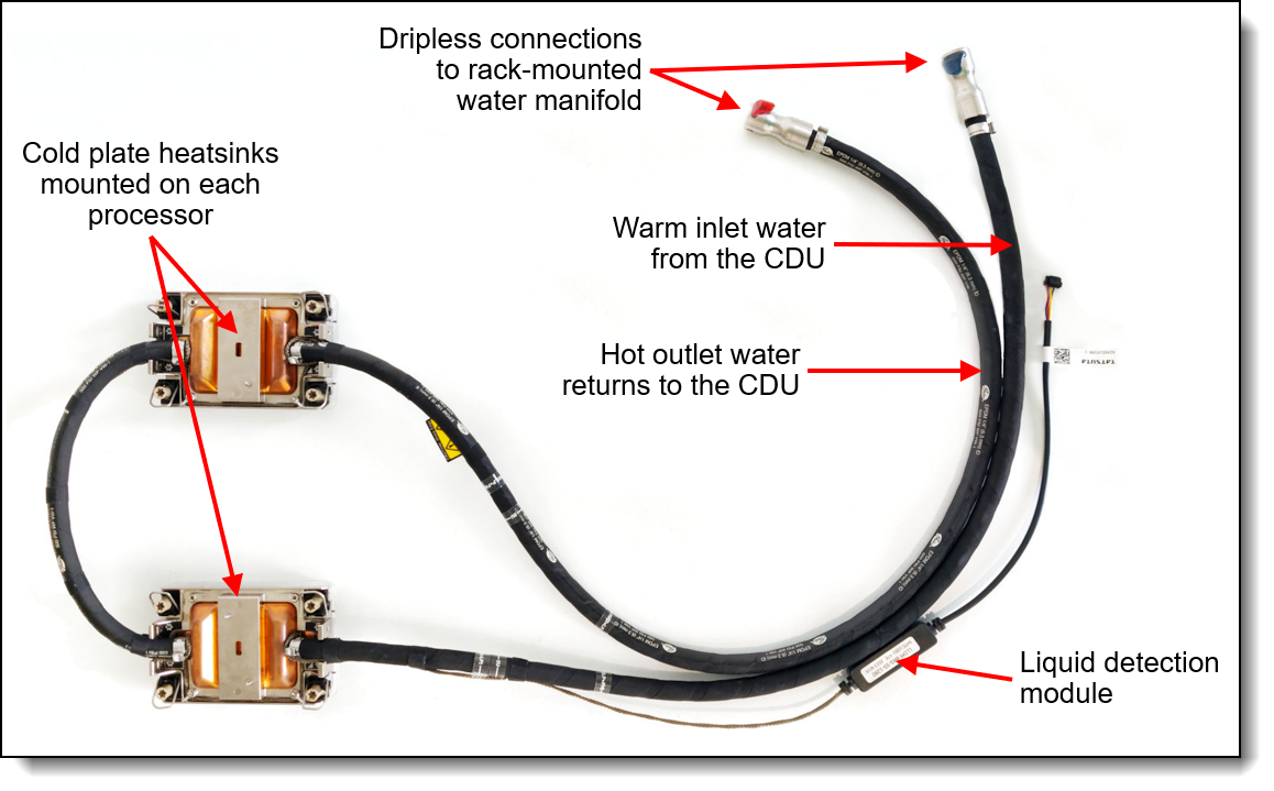
Figure 7. Lenovo Processor Neptune Core Module
The Processor Neptune Core Module also includes a leak detection module which can detect a leakage of more than 0.5ml (about 10 drops) along the length of the tube and then issue an event to the XClarity Controller. XCC will then post an error to the System Event Log and enable further actions. Once the liquid evaporates, a further event is issue to XCC.
The Processor Neptune Core Module is only available in CTO orders, not as a field upgrade. Ordering information is listed in the following table.
| Part number | Feature code | Description | Top Choice Express |
|---|---|---|---|
| CTO only | BXBC* | ThinkSystem V3 1U/2U Neptune Processor Direct Water Cooling Solution | Not TCE |
* In DCSC, this feature code is listed in the Processor tab
Configuration notes:
- The Processor Neptune Core Module requires water infrastructure be available in the rack cabinet and data center, as described in the Water infrastructure section.
- All processor SKUs are supported
- Either one or two CPUs are supported
- All front drive bay configurations are supported
- Slot 6 is not available for adapters - the water loop is routed through the space otherwise occupied by slot 6
- Rear drive bays are supported
- 7mm drive bays are supported only in slot 3
- M.2 adapters are supported based on the configurations in the Storage configurations section
- Standard fans can be configured in most configurations
- The use of a cable management arm (CMA) is not supported
For more information, see the Thermal Rules page:
https://pubs.lenovo.com/sr650-v3/thermal_rules
The following figure shows the Lenovo Neptune Processor DWC Module installed in the SR650 V3 (risers removed to show internal components).
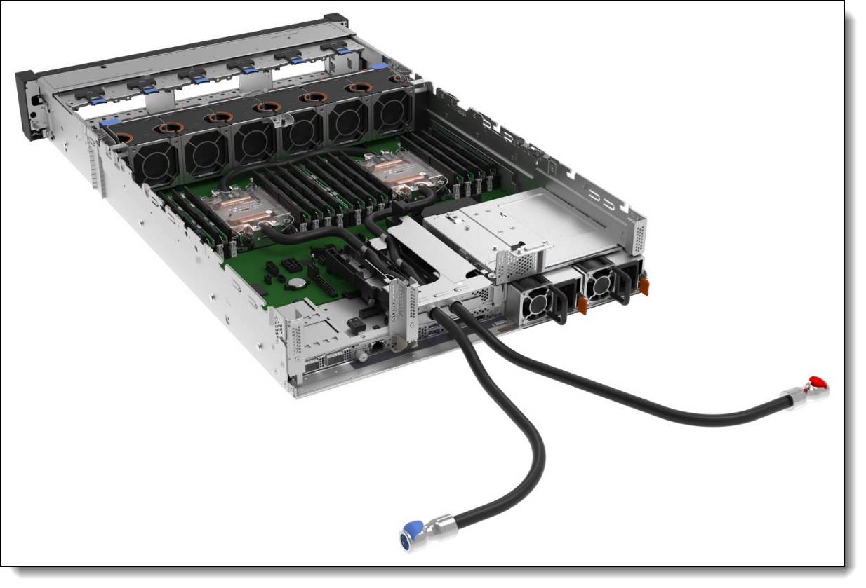
Figure 8. Lenovo Neptune Processor DWC Module installed in the SR650 V3
UEFI operating modes
The SR650 V3 offers preset operating modes that affect energy consumption and performance. These modes are a collection of predefined low-level UEFI settings that simplify the task of tuning the server to suit your business and workload requirements.
The following table lists the feature codes that allow you to specify the mode you wish to preset in the factory for CTO orders.
UK and EU customers: For compliance with the ERP Lot9 regulation, you should select feature BFYE. For some systems, you may not be able to make a selection, in which case, it will be automatically derived by the configurator.
The preset modes for the SR650 V3 are as follows:
- Maximum Performance Mode (feature BFYB): Achieves maximum performance but with higher power consumption and lower energy efficiency.
- Minimal Power Mode (feature BFYC): Minimize the absolute power consumption of the system.
- Efficiency Favoring Power Savings Mode (feature BFYD): Maximize the performance/watt efficiency with a bias towards power savings. This is the favored mode for SPECpower benchmark testing, for example.
- Efficiency Favoring Performance Mode (feature BFYE): Maximize the performance/watt efficiency with a bias towards performance. This is the favored mode for Energy Star certification, for example.
For details about these preset modes, and all other performance and power efficiency UEFI settings offered in the SR650 V3, see the paper "Tuning UEFI Settings for Performance and Energy Efficiency on Intel Xeon Scalable Processor-Based ThinkSystem Servers", available from https://lenovopress.lenovo.com/lp1477.
Memory options
The SR650 V3 uses Lenovo TruDDR5 memory operating at up to 5600 MHz. The server supports up to 32 DIMMs with 2 processors. The processors have 8 memory channels and support 2 DIMMs per channel (DPC). The server supports up to 8TB of memory using 32x 256GB 3DS RDIMMs and two processors.
With 5th Gen Intel Xeon processors, DIMMs operate at the following speeds, up to the memory bus speed of the processor selected. See the Processor features section for specifics.
- 1 DIMM per channel (DPC) using RDIMMs: Up to 5600 MHz
- 1 DPC using 3DS RDIMMs: Up to 5200 MHz
- 2 DPC using RDIMMs or 3DS RDIMMs: Up to 4400 MHz
- 2 DPC using Performance+ RDIMMs: Up to 4800 MHz
With 4th Gen Intel Xeon processors, DIMMs operate at the following speeds, up to the memory bus speed of the processor selected:
- 1 DPC: Up to 4800 MHz
- 2 DPC: Up to 4400 MHz
Lenovo TruDDR5 memory uses the highest quality components that are sourced from Tier 1 DRAM suppliers and only memory that meets the strict requirements of Lenovo is selected. It is compatibility tested and tuned to maximize performance and reliability. From a service and support standpoint, Lenovo TruDDR5 memory automatically assumes the system warranty, and Lenovo provides service and support worldwide.
The following table lists the 5600 MHz memory options that are currently supported by the SR650 V3. These DIMMs are only supported with 5th Gen Intel Xeon processors, with the exceptions listed in the memory rules below.
The following table lists the 4800 MHz memory options that are currently supported by the SR650 V3. These DIMMs are only supported with 4th Gen Intel Xeon processors plus four specific 5th Gen processors as listed in the memory rules below. The 128GB 5600MHz RDIMM is also supported with 4th Gen processors.
9x4 RDIMMs (also known as EC4 RDIMMs) are a new lower-cost DDR5 memory option supported in ThinkSystem V3 servers. 9x4 DIMMs offer the same performance as standard RDIMMs (known as 10x4 or EC8 modules), however they support lower fault-tolerance characteristics. Standard RDIMMs and 3DS RDIMMs support two 40-bit subchannels (that is, a total of 80 bits), whereas 9x4 RDIMMs support two 36-bit subchannels (a total of 72 bits). The extra bits in the subchannels allow standard RDIMMs and 3DS RDIMMs to support Single Device Data Correction (SDDC), however 9x4 RDIMMs do not support SDDC. Note, however, that all DDR5 DIMMs, including 9x4 RDIMMs, support Bounded Fault correction, which enables the server to correct most common types of DRAM failures.
For more information on DDR5 memory, see the Lenovo Press paper, Introduction to DDR5 Memory, available from https://lenovopress.com/lp1618.
The following rules apply when selecting the memory configuration:
- In DCSC, 4800 MHz memory can only be selected with 4th Gen Intel Xeon Scalable processors, and 5600 MHz memory can only be selected with 5th Gen Intel Xeon Scalable processors. The only exceptions are listed below.
- An exception to the above rule is the following 5600 MHz DIMM which is supported with both 4th Gen and 5th Gen processors (operates at up to 4800 MHz with 4th Gen processors):
- ThinkSystem 128GB TruDDR5 5600MHz (2Rx4) RDIMM, 4X77A93887
- An additional exception to the above rule are the following 5th Gen processors:
- Intel Xeon Bronze 3508U 8C 125W 2.1GHz Processor
- Intel Xeon Silver 4509Y 8C 125W 2.6GHz Processor
- Intel Xeon Silver 4510 12C 150W 2.4GHz Processor
- Intel Xeon Silver 4510T 12C 115W 2.0GHz Processor
These 4 processors support:
- All 4800 MHz memory DIMMs
- ThinkSystem 16GB TruDDR5 5600MHz (1Rx8) RDIMM, 4X77A88087
- ThinkSystem 32GB TruDDR5 5600MHz (2Rx8) RDIMM, 4X77A88051
- ThinkSystem 64GB TruDDR5 5600MHz (2Rx4) RDIMM, 4X77A88052
- ThinkSystem 128GB TruDDR5 5600MHz (2Rx4) RDIMM, 4X77A93887
- The SR650 V3 only supports quantities of 1, 2, 4, 6, 8, 12, or 16 DIMMs per processor; other quantities not supported. Additional quantity requirements:
- 5th Gen Intel Xeon processors:
- 24GB and 48GB DIMMs are only supported in quantities 1, 6, 8 per processor (2, 4, 12, 16 not supported)
- 96GB DIMMs are only supported in quantities 1, 6, 8, 12, 16 per processor (2, 4 not supported)
- 4th Gen Intel Xeon processors:
- 24GB and 48GB DIMMs are only supported in quantity 8 per processor
- 96GB DIMMs are only supported in quantities 8, 16 per processor
- 5th Gen Intel Xeon processors:
- The 48GB RDIMM (4X77A87033) and 96GB RDIMM (4X77A87034) are supported with all 4th Gen processors
- The server supports three types of DIMMs: 9x4 RDIMMs, RDIMMs, and 3DS RDIMMs; UDIMMs and LRDIMMs are not supported
- Mixing of DIMM types is not supported (9x4 DIMMs with 10x4 RDIMMs, 9x4 DIMMs with 3DS RDIMMs, 10x4 RDIMMs with 3DS RDIMMs)
- Mixing of DRAM technology (16Gb, 24Gb, 32Gb) is not supported. See the column in the above table.
- Mixing of 24GB, 48GB and 96GB DIMMs (24Gb DRAM) is not supported; if using any of these DIMMs then all installed memory must be the same part number
- Mixing x4 and x8 DIMMs is not supported
- Mixing of DIMM rank counts is supported. Follow the required installation order installing the DIMMs with the higher rank counts first.
- Mixing of DIMM capacities is supported, however only two different capacities are supported across all channels of the processor. Follow the required installation order installing the larger DIMMs first.
- Memory mirroring is not supported with 9x4 DIMMs
- The mixing of 128GB 3DS RDIMMs and 256GB 3DS RDIMMs is supported
- The use of the 128GB 3D RDIMM feature BY8F has the following requirements for thermal reasons:
- If the front drive bays are 12x 3.5-inch, then middle and rear drive bays are not supported
- Additional ambient temperature requirements - see https://pubs.lenovo.com/sr650-v3/thermal_rules for information
For best performance, consider the following:
- Ensure the memory installed is at least the same speed as the memory bus of the selected processor.
- Populate all 8 memory channels.
The following memory protection technologies are supported:
- ECC detection/correction
- Bounded Fault detection/correction
- SDDC (for 10x4-based memory DIMMs; look for "x4" in the DIMM description)
- ADDDC (for 10x4-based memory DIMMs, not supported with 9x4 DIMMs)
- Memory mirroring
See the Lenovo Press article, RAS Features of the Lenovo ThinkSystem Intel Servers for more information about memory RAS features.
If memory channel mirroring is used, then DIMMs must be installed in pairs (minimum of one pair per processor), and both DIMMs in the pair must be identical in type and size. 50% of the installed capacity is available to the operating system.
Memory rank sparing is implemented using ADDDC/ADC-SR/ADDDC-MR to provide DRAM-level sparing feature support.
Internal storage
The SR650 V3 has three drive bay zones and supports up to 20x 3.5-inch or 40x 2.5-inch hot-swap drive bays or a combination of drive bays, depending on the selected chassis and backplane configuration. The server also supports configurations without any drive bays if desired.
The three drive bay zones are as follows:
- Front:
- Up to 12x 3.5-inch hot-swap bays, or
- Up to 24x 2.5-inch hot-swap bays
- Middle:
- 4x 3.5-inch simple-swap bays, or
- 8x 2.5-inch simple-swap bays
- Rear:
- Up to 4x 3.5-inch hot-swap bays, or
- Up to 8x 2.5-inch hot-swap bays
- Also supports 2x 7mm hot-swap drives bays
The server also supports one or two M.2 drives, installed in an M.2 adapter internal to the server.
In this section:
NVMe drive support
The SR650 V3 supports NVMe drives to maximize storage performance.
- Up to 36 NVMe drives in a 2.5-inch drive configuration, without oversubscription (that is, each x4 drive has a dedicated x4 (4 lanes) connection to the processor, either direct to the processor or via a retimer adapter)
- Up to 24 installed in front bays
- Up to 28 installed in the front and rear bays
- Up to 32 installed in front and mid bays
- Up to 36 installed in front, mid and rear bays
- Up to 8 NVMe drives in a 3.5-inch drive configuration, without oversubscription
- All installed in mid bays
Riser 3 support with onboard NVMe: When Riser 3 is configured, the use of the onboard NVMe connections is supported up to 12x NVMe drives. Two 8-bay backplanes are required, with 4 bays unused. A quantity of 16x or more NVMe drives requires the use of an adapter if Riser 3 is configured.
The specifics of these configurations are covered in the Storage configurations section. The tables in those sections indicate the number of NVMe drives in each configuration.
In addition, the SR650 V3 supports two 7mm NVMe drives for use as boot drives.
Tri-Mode support - RAID 940 and RAID 9450 adapters
The RAID 940 and RAID 9450 adapters support NVMe through a feature named Tri-Mode support (or Trimode support). This feature enables the use of NVMe U.3 drives at the same time as SAS and SATA drives. Tri-Mode requires an AnyBay backplane. Cabling of the controller to the backplanes is the same as with SAS/SATA drives, and the NVMe drives are connected via a PCIe x1 link to the controller.
NVMe drives connected using Tri-Mode support provide better performance than SAS or SATA drives: A SATA SSD has a data rate of 6Gbps, a SAS SSD has a data rate of 12Gbps, whereas an NVMe U.3 Gen 4 SSD with a PCIe x1 link will have a data rate of 16Gbps. NVMe drives typically also have lower latency and higher IOPS compared to SAS and SATA drives. Tri-Mode is supported with U.3 NVMe drives and requires an AnyBay backplane.
Tri-Mode requires U.3 drives: Only NVMe drives with a U.3 interface are supported. U.2 drives are not supported. See the Internal drive options section for the U.3 drives supported by the server.
NVMe x4 support (not Tri-Mode): As an alternative to Tri-Mode support, the RAID 9450-32i adapter supports connectivity to either NVMe U.2 and U.3 drives using a PCIe Gen4 x4 connection. A x4 connection to each drive enables maximum performance from the NVMe drives. Note that a x4 connection requires different cabling than a Tri-Mode connection. Only NVMe drives are supported; SAS and SATA drives are not supported.
Front drive bays
The front drive bay zone supports the following configurations:
- 8x or 12x 3.5-inch drive bays (all hot-swap)
- 8x, 16x or 24x 2.5-inch drive bays (all hot-swap)
- 4x 2.5-inch drive bays (all hot-swap) with support for front PCIe slots
- No backplanes and no drives (supports field upgrades)
The specific combinations that are supported in the SR650 V3 are shown in the following figures. The feature codes listed are the backplane feature codes when ordering CTO and correspond to the feature codes listed in the table below the figure. Note that NVMe and AnyBay backplanes may be available either PCIe Gen4 (G4) or PCIe Gen5 (G5) as listed in the figures.
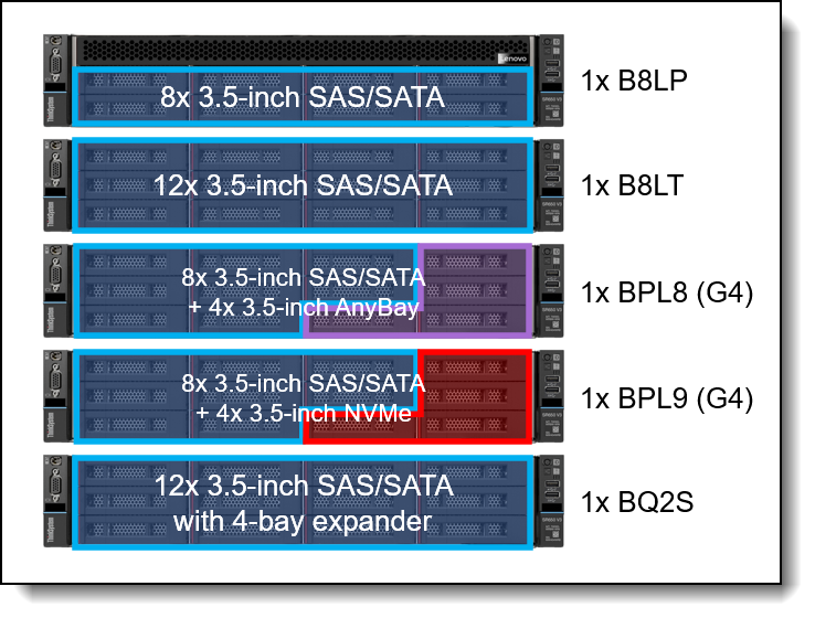
Figure 9. SR650 V3 front drive bay configurations - 3.5-inch drive bays
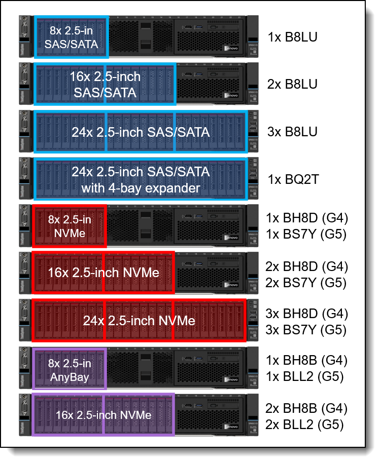
Figure 10. SR650 V3 front drive bay configurations - 2.5-inch drive bays, all the same drive type
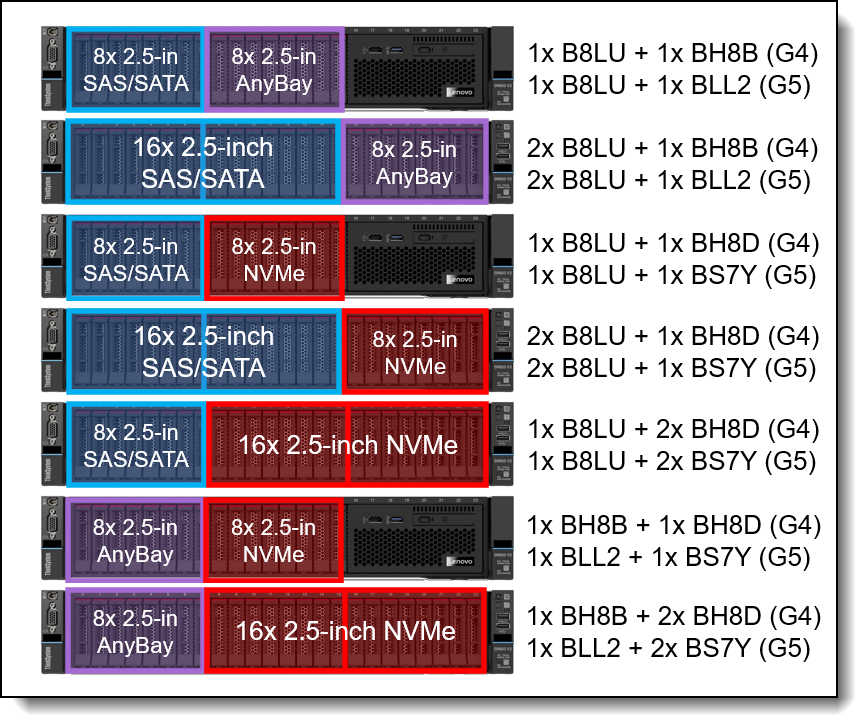
Figure 11. SR650 V3 front drive bay configurations - 2.5-inch drive bays, combinations
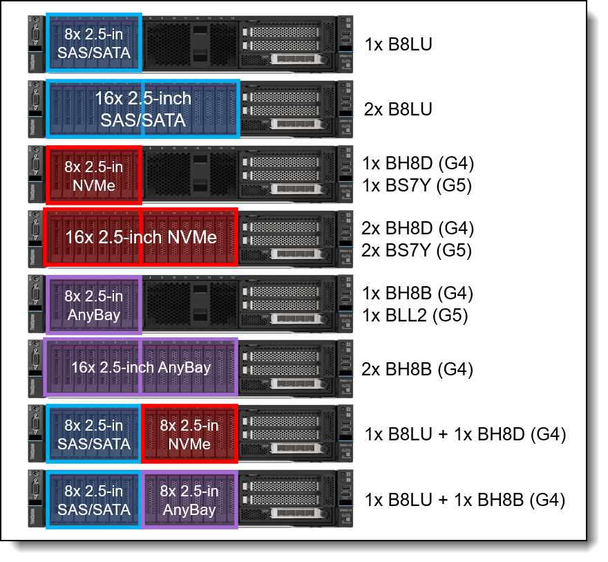
Figure 12. SR650 V3 front drive bay configurations - 2.5-inch drive bays with front PCIe slots
The backplanes used to provide these drive bays are listed in the following table. The table includes a Top Choice Express column; for CTO orders, select a TCE component for faster delivery. See the Top Choice section for more information.
Field upgrades: All front backplanes are available as part numbers for field upgrades along with require cable option kits, as described in the Field upgrades section below.
* Backplane has an onboard SAS expander that provides connectivity to front SAS/SATA drive bays using only an 8-port controller, plus support for 4x rear drives in a separate backplane (order the rear backplane separately). See below for additional information and requirements.
The use of front drive bays has the following configuration rules:
- The SR650 V3 also supports configurations without any drive bays, allowing for drive bay upgrades as described in the field upgrades section.
- Most backplanes require connections to controllers that provides enough ports to connect each drive (eg 8 ports for an 8-bay backplane). The only exceptions to that are the backplanes with built-in SAS expanders - these backplanes require a fewer number of controller ports to connect to the front drives, and also include a connection to up to 4x rear drive bays. Connections to mid-chassis backplanes or to 8x rear drive bays require additional controller ports. Supported connections are as follows:
- For the ThinkSystem 2U 12x3.5" SAS/SATA with Rear 4-Bay Expander Backplane, feature BQ2S:
- 12x3.5" front drives only: requires a single 8i controller
- 12x3.5” + 4x3.5” (Rear): requires a single 8i controller, 8i to front+rear
- 12x3.5” + 4x3.5” (Mid): requires 16i controller - 8i to front, 8i to middle
- 12x3.5” + 4x3.5” (Mid) + 4x3.5” (Rear): requires 16i controller, 8i to front+rear, 8i to middle
- For the ThinkSystem 2U 24x2.5" SAS/SATA with Rear 4-Bay Expander Backplane, feature BQ2T:
- 24x2.5” front drives only: requires a single 8i controller
- 24x2.5” + 4x2.5” (Rear): requires a single 8i controller, 8i to front+rear
- 24x2.5” + 8x2.5” (Mid): requires 16i controller - 8i to front, 8i to middle
- 24x2.5” + 8x2.5” (Mid) + 8x2.5” (Rear): requires 32i controller - 8i to front, 8i to middle, 8i to rear
For specifics configurations, see the Storage configurations section.
- For the ThinkSystem 2U 12x3.5" SAS/SATA with Rear 4-Bay Expander Backplane, feature BQ2S:
- If you are building a server configuration that includes the ThinkSystem 2U 24x2.5" SAS/SATA with Rear 4-Bay Expander Backplane (feature BQ2T) and the order also includes a rack cabinet, then you can configure at most 6 drives to be installed in the factory. The remaining drives must be ordered separately using the option part numbers for the drives. This requirement does not apply if the order does not include a rack cabinet. The requirement is due to the shock/vibration limits of the 24x 2.5-inch backplane.
- If 3.5-inch front drive bays are used, an internal (CFF) RAID adapter or HBA is not supported as the adapter and bays occupy the same physical space
- Any 8x 2.5-inch and 16x 2.5-inch drive configuration (SAS/SATA, AnyBay, or NVMe) can optionally be configured for use with the Integrated Diagnostics Panel as described in the Local management section. 3.5-inch drive configurations do not support the Integrated Diagnostics Panel. With the Integrated Diagnostics Display, 8-bay configurations can be upgrade to 16 bays, however 16-bay configurations cannot be upgrade to 24 bays.
- The following backplanes with integrated SAS expanders are not supported with cluster applications. For more information see Support Tip TT3693:
- ThinkSystem 2U 12x3.5" SAS/SATA with Rear 4-Bay Expander Backplane (BQ2S)
- ThinkSystem 2U 24x2.5" SAS/SATA with Rear 4-Bay Expander Backplane (BQ2T)
Mid drive bays
The SR650 V3 supports simple-swap drives installed in the middle of the server chassis. The drive bays are accessible by removing the top lid of the server and levering the mid drive chassis up at the front.
The following configurations are supported:
- 4x 3.5-inch simple-swap SAS/SATA drive bays
- 8x 2.5-inch simple-swap SAS/SATA drive bays
- 8x 2.5-inch simple-swap NVMe drive bays
The drive bays in the open position are shown in the following figure.
Simple-swap drive bays: The drives that are installed in the mid-chassis drive bays are simple-swap, not hot-swap, even though the drives use hot-swap drive trays.
M.2 support: When mid drive bays are configured, the M.2 adapter is installed on the mid drive bay mechanical as shown in the images.
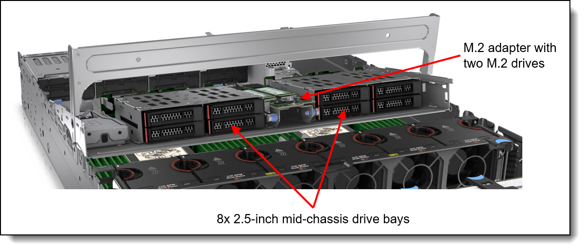
Figure 13. Mid-chassis drive bays
The backplanes used to provide these drive bays are listed in the following table. The table includes a Top Choice Express column; for CTO orders, select a TCE component for faster delivery. See the Top Choice section for more information.
‡ 2.5-inch drive backplanes for the mid-chassis area must be installed in pairs. NVMe and SAS/SATA cannot be mixed.
Field upgrades: Backplanes are available as part numbers for field upgrades along with require cable option kits, as described in the Field upgrades section below.
The use of drive bays in the mid-chassis area has the following configuration rules:
- All processors are supported. Higher TDP processors will require the performance heatsinks.
- Full-length adapter cards are not supported
- GPUs (including low profile GPUs such as the NVIDIA A2) are not supported
- The use of mid drive bays requires Riser 1 be installed, since power for the mid bay backplanes comes from Riser 1
Rear drive bays
The SR650 V3 supports hot-swap drives installed at the rear of the server chassis. Supported configurations are as follows:
- 3.5-inch hot-swap drives
- 2x SAS/SATA drive bays
- 4x SAS/SATA drive bays
- 2.5-inch hot-swap drives
- 4x SAS/SATA drive bays
- 4x NVMe Gen5 drive bays
- 4x AnyBay Gen5 drive bays
- 8x SAS/SATA drive bays
The configurations are shown in the following figure.
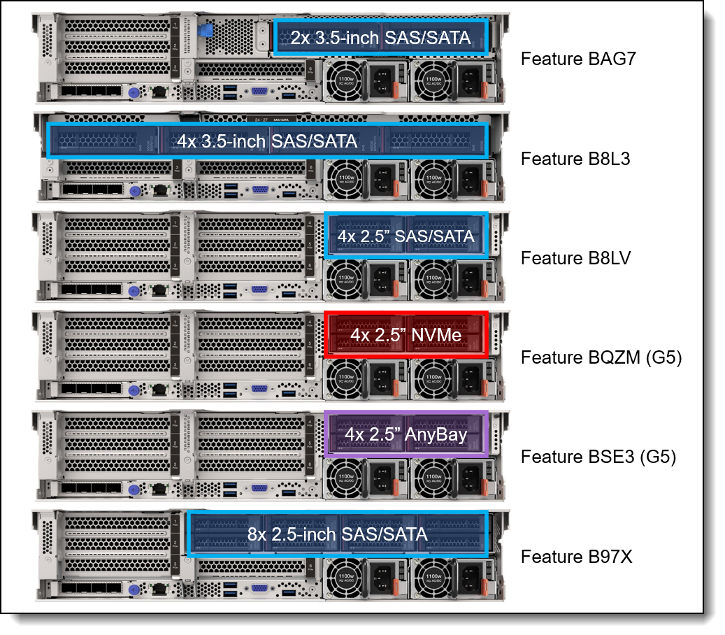
Figure 14. Rear 2.5-inch and 3.5-inch drive bay configurations
The backplanes used to provide these drive bays are listed in the following table. The table includes a Top Choice Express column; for CTO orders, select a TCE component for faster delivery. See the Top Choice section for more information.
7mm drives: The SR650 V3 supports two 7mm drives. See the 7mm drives section for details.
Field upgrades: Backplanes are available as part numbers for field upgrades along with require cable option kits, as described in the Field upgrades section below.
The use of rear drive bays has the following configuration rules:
- The use of rear bays restricts the number of slots and the choice of risers that are supported. See the I/O expansion section for details.
- The use of rear drive bays may require that Riser 1 or Riser 2 be installed, since power for the rear backplane comes from that riser.
- Configurations with 4x 2.5-inch rear drive bays are not supported with 7mm drive bays, as they use the same power connector
Storage configurations
This section describes the various combinations of front and rear drives that the server supports, as well as M.2 support.
Tip: These tables are based on Config Matrix V5.6 in TRD V3.63
In this section:
- Overview of configurations - 3.5-inch front drive bays
- Overview of configurations - 2.5-inch front drives supporting rear slots (no front PCIe slots)
- Overview of configurations - 2.5-inch front drives supporting 12 PCIe slots (front & rear)
- Details - 3.5-inch front drive bays
- Details - 2.5-inch front drives supporting rear slots (no front PCIe slots)
- Details - 2.5-inch front drives supporting 12 PCIe slots (front & rear)
The following tables summarize the storage configurations for the SR650 V3. For details, including processor requirements, M.2 and 7mm support, and controller selections, see each of the Details tables.
Platinum processor support: Some storage configurations are only supported with certain processors:
- Configurations with "NP" (No Platinum) in the CPU column are supported with Bronze, Silver and Gold processors, but not Platinum processors.
- Configurations with "PO" (Platinum Only) in the CPU column are only supported with Platinum processors
For example, config 98-1 is only for Platinum processors, however config 98-2 is for all other processors.
Overview - 3.5-inch front drives
The following table summarizes the configurations that use 3.5-inch front drive bays.
Click to jump down to the details of the 3.5-inch front drive configurations.
Return to Storage configurations.
Field upgrades: For part number upgrades, see the Drive bays field upgrades - 3.5-inch chassis section.
Overview - 2.5-inch front drives supporting rear slots (no front PCIe slots)
The following table summarizes the configurations that use 2.5-inch front drives supporting rear slots (no front PCIe slots).
Click to jump down to the details of the 2.5-inch front drive configurations.
Return to Storage configurations.
Field upgrades: For part number upgrades, see the following:
Overview - 2.5-inch front drives supporting 12 PCIe slots (front & rear)
The following table summarizes the configurations that use 2.5-inch front drives supporting 12 PCIe slots (front & rear). Such a configuration supports up to 16x 2.5-inch drive bays + PCIe slots at the front of the server.
Click to jump down to the details of the 2.5-inch front drive configurations.
Return to Storage configurations.
Field upgrades: For part number upgrades, see the Drive bay field upgrades - 2.5-inch chassis with front slots section.
Details - 3.5-inch front bays
The following table details the configurations that use 3.5-inch front drive bays.
Click to go to the overview of the 3.5-inch front drive configurations.
Return to Storage configurations.
In the table:
- M.2 + VROC (SATA) means the M.2 SATA/x4 NVMe adapter (4Y37A79663) with SATA drives. RAID is optional, provided using VROC.
- M.2 + VROC (NVMe) means the M.2 SATA/x4 NVMe adapter (4Y37A79663) with NVMe drives. RAID is optional, provided using VROC.
- M.2 + RAID adapter means the M.2 SATA/x4 NVMe adapter (4Y37A79663) with either a RAID 5350-8i adapter (supporting SATA drives) or a RAID 540-8i (supporting NVMe drives). Adapter installs in a rear PCIe slot.
- M.2 Integrated RAID means the M.2 RAID NVMe adapter (B8P9) with a Marvell controller or the M.2 RAID B540i-2i SATA/NVMe Adapter with a Broadcom controller. RAID-0 and RAID-1 are supported.
- 7mm + VROC (SATA) means the 7mm SATA/NVMe kit (BU0N) with SATA drives. RAID is optional, provided using VROC.
- 7mm + VROC (NVMe) means the 7mm SATA/NVMe kit (BU0N) with NVMe drives. RAID is optional, provided using VROC.
- 7mm + RAID adapter means the 7mm SATA/NVMe kit (BU0N) with either a RAID 5350-8i adapter (supporting SATA drives) or a RAID 540-8i (supporting NVMe drives). Adapter installs in a rear PCIe slot.
- 7mm Integrated RAID means the 7mm NVMe RAID kit (B8P3) with a Marvell controller or the 7mm SATA/NVMe RAID kit (BYFG) with a Broadcom controller. RAID-0 and RAID-1 are supported.
Tip: M.2 and 7mm are mutually exclusive: they are not supported together in the same configuration
* For M.2 or 7mm: Requires 2 processors; 1P not supported
Details - 2.5-inch front bays supporting rear slots (no front PCIe slots)
The following table details the configurations that use 2.5-inch front bays supporting rear slots (no front PCIe slots).
Click to go to the overview of the 2.5-inch front drive configurations.
Return to Storage configurations.
In the table:
- M.2 + VROC (SATA) means the M.2 SATA/x4 NVMe adapter (4Y37A79663) with SATA drives. RAID is optional, provided using VROC.
- M.2 + VROC (NVMe) means the M.2 SATA/x4 NVMe adapter (4Y37A79663) with NVMe drives. RAID is optional, provided using VROC.
- M.2 + RAID adapter means the M.2 SATA/x4 NVMe adapter (4Y37A79663) with either a RAID 5350-8i adapter (supporting SATA drives) or a RAID 540-8i (supporting NVMe drives)
- M.2 Integrated RAID means the M.2 RAID NVMe adapter (B8P9) with a Marvell controller or the M.2 RAID B540i-2i SATA/NVMe Adapter with a Broadcom controller. RAID-0 and RAID-1 are supported.
- 7mm + VROC (SATA) means the 7mm SATA/NVMe kit (BU0N) with SATA drives. RAID is optional, provided using VROC.
- 7mm + VROC (NVMe) means the 7mm SATA/NVMe kit (BU0N) with NVMe drives. RAID is optional, provided using VROC.
- 7mm + RAID adapter means the 7mm SATA/NVMe kit (BU0N) with either a RAID 5350-8i adapter (supporting SATA drives) or a RAID 540-8i (supporting NVMe drives)
- 7mm Integrated RAID means the 7mm NVMe RAID kit (B8P3) with a Marvell controller or the 7mm SATA/NVMe RAID kit (BYFG) with a Broadcom controller. RAID-0 and RAID-1 are supported.
Tip: M.2 and 7mm are mutually exclusive: they are not supported together in the same configuration
* For M.2 or 7mm: Requires 2 processors; 1P not supported
† NP (No Platinum) means the configuration does not support Platinum processors — only Bronze, Silver and Gold are supported. PO (Platinum Only) means the configuration only supports Platinum processors.
Details - 2.5-inch front drives supporting 12 PCIe slots (front & rear)
The following table details the configurations that use 2.5-inch front drives supporting 12 PCIe slots (front & rear). Such a configuration supports up to 16x 2.5-inch drive bays + PCIe slots at the front of the server.
Click to go to the overview of the 2.5-inch front drive configurations.
Return to Storage configurations.
In the table:
- M.2 + VROC (SATA) means the M.2 SATA/x4 NVMe adapter (4Y37A79663) with SATA drives. RAID is optional, provided using VROC.
- M.2 + VROC (NVMe) means the M.2 SATA/x4 NVMe adapter (4Y37A79663) with NVMe drives. RAID is optional, provided using VROC.
- M.2 + RAID adapter means the M.2 SATA/x4 NVMe adapter (4Y37A79663) with either a RAID 5350-8i adapter (supporting SATA drives) or a RAID 540-8i (supporting NVMe drives)
- M.2 Integrated RAID means the M.2 RAID NVMe adapter (B8P9) with a Marvell controller or the M.2 RAID B540i-2i SATA/NVMe Adapter with a Broadcom controller. RAID-0 and RAID-1 are supported.
- 7mm + VROC (SATA) means the 7mm SATA/NVMe kit (BU0N) with SATA drives. RAID is optional, provided using VROC.
- 7mm + VROC (NVMe) means the 7mm SATA/NVMe kit (BU0N) with NVMe drives. RAID is optional, provided using VROC.
- 7mm + RAID adapter means the 7mm SATA/NVMe kit (BU0N) with either a RAID 5350-8i adapter (supporting SATA drives) or a RAID 540-8i (supporting NVMe drives)
- 7mm Integrated RAID means the 7mm NVMe RAID kit (B8P3) with a Marvell controller or the 7mm SATA/NVMe RAID kit (BYFG) with a Broadcom controller. RAID-0 and RAID-1 are supported.
Tip: M.2 and 7mm are mutually exclusive: they are not supported together in the same configuration
* For M.2 or 7mm: Requires 2 processors; 1P not supported
Field upgrades
The SR650 V3 is orderable without drive bays, allowing you to add a backplane, cabling and controllers as field upgrades. The server also supports upgrading some configurations by adding additional front drive bays (for example, upgrading from 8 to 16x 2.5-inch drive bays).
Upgrade path: The key criteria for upgrade support is to ensure that the target configuration is one of the supported drive bay configurations as listed in the Storage configurations section.
For example, if you are upgrading a 2.5-inch SAS/SATA drive configuration from 8 bays (Config 9) to 16 bays (Config 12), you will need these additional options:
- 4XH7A60930, ThinkSystem V3 2U 8x2.5" SAS/SATA Backplane Option Kit
- 4X97A82935, ThinkSystem SR650 V3 2.5" Chassis Front BP2 SAS/SATA Cable Kit
To add drive bays you will need to order both drive backplanes and cable kits. Backplane kits do not include cables.
In this section:
- Drive bay field upgrades - 3.5-inch chassis
- Drive bay field upgrades - 2.5-inch chassis with SAS/SATA and Gen4 front bays
- Drive bay field upgrades - 2.5-inch chassis with Gen5 front bays
- Drive bay field upgrades - 2.5-inch chassis with front slots
- Upgrading to an internal (CFF) adapter
- 2.5-inch drive bay fillers
Drive bay field upgrades - 3.5-inch chassis
The table below lists the backplane kits and cable kits needed to build one of the supported 3.5-inch chassis configurations.
The Config numbers listed here match the configuration listed in the Storage configuration Overview and Details sections.
Return to Field upgrades.
For more information about the backplane kits and cable kits, see the Lenovo server options site:
https://serveroption.lenovo.com/cable_kit_options/
Drive bay field upgrades - 2.5-inch chassis with SAS/SATA and Gen4 front bays
The tables below lists the backplane kits and cable kits needed to build one of the supported 2.5-inch chassis configurations with either SAS/SATA or Gen4 front backplanes.
The Config numbers listed here match the configuration listed in the Storage configuration Overview and Details sections.
Return to Field upgrades.
Note: Front drive cable kits are based on the location of the backplane in the server. The three backplane locations are BP1, BP2 and BP3 as shown in the following figure.
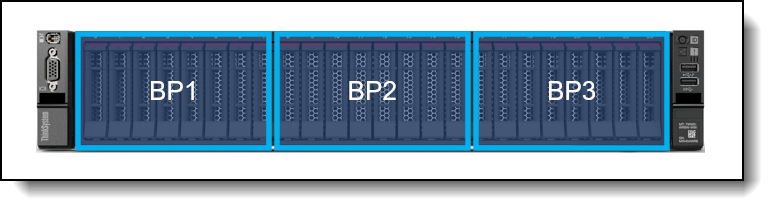
Figure 15. Backplane numbering
For more information about the backplane kits and cable kits, see the Lenovo server options site:
https://serveroption.lenovo.com/cable_kit_options/
Drive bay field upgrades - 2.5-inch chassis with Gen5 front bays
The tables below lists the backplane kits and cable kits needed to build one of the supported 2.5-inch chassis configurations with Gen5 NVMe or AnyBay front backplanes.
The Config numbers listed here match the configuration listed in the Storage configuration Overview and Details sections.
Return to Field upgrades.
Drive bay field upgrades - 2.5-inch chassis with front slots
The tables below lists the backplane kits and cable kits needed to build one of the supported 2.5-inch chassis configurations with front and rear.
The Config numbers listed here match the configuration listed in the Storage configuration Overview and Details sections.
Return to Field upgrades.
Upgrading to an internal (CFF) adapter
If you want to add an internal (CFF) storage adapter (HBA, RAID adapter or SAS expander) to a configuration, you will need to order the cable kit as listed in the following table. Suitable upgrades are either replacing an existing adapter in a rear PCIe slot, or adding the CFF adapter to a server without any storage adapter installed.
The cable kit to order is listed in the following table.
| Part number | Description |
|---|---|
| 4X97A82941 | ThinkSystem SR650 V3 Internal HBA/RAID Adapter Cable Kit |
The cable kit includes the cables need to connect to backplanes. Contents of the kit is listed in the following page:
https://serveroption.lenovo.com/cable_kit_options/cable_kit_sr650v3_internal_hba_raid_adapter
When adding drive bays, you will also need to add the appropriate CFF storage controller.
RAID flash power module (supercap) support
If you plan to add one of the RAID adapters that includes a RAID flash power module (supercap) as a field upgrade, then you may also need to order a Supercap installation kit for the supercap, depending on the location where the supercap will be installed. For CTO orders, the components needed are automatically derived when you select the RAID adapter.
The adapters that this applies to are as follows:
- Any supported RAID 9350 adapter
- Any supported RAID 940 adapter
The location of the supercaps depends on the mid-chassis drive cage used in the server, as shown in the following table.
For 3.5-inch drive bay configurations, if the server already has 3.5-inch mid-chassis drive bays, then the supercap holder is already present under the system fan cages. If you plan to add 3.5-inch mid-chassis drive bays by adding ThinkSystem SR650 V3 Middle 4x3.5" SAS/SATA Backplane Option Kit (4XH7A82916), then the supercap holder is part of the option kit.
7mm drives
The SR650 V3 supports two 7mm drives, either both SATA or both NVMe, at the rear of the server. These drives go in place of either PCIe slot 3 (Riser 1) or PCIe slot 6 (Riser 2) as shown in the following figure.
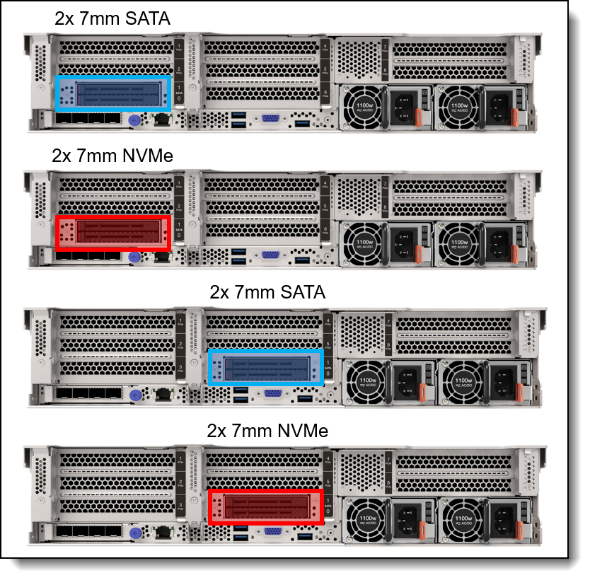
Figure 16. Rear 7mm drive bay configurations
For CTO orders, the configuration includes the drive bays and the cage the the drive bays are mounted on to.The cage required depends on where the 7mm drives are located (Riser 1 or Riser 2) and whether there are PCIe slots above the 7mm drive bays.
The following table lists the ordering information. The table includes a Top Choice Express column; for CTO orders, select a TCE component for faster delivery. See the Top Choice section for more information.
The use of the 7mm rear drive bays has the following configuration rules:
- The 7mm rear drive kit is supported in either slot 3 or slot 6 but not both at the same time.
- 7mm drive bays are not supported in configurations with 4x 2.5-inch rear drive bays, as they use the same power connector
- M.2 and 7mm are mutually exclusive: they are not supported together in the same configuration
- For ThinkSystem 7mm SATA/NVMe 2-Bay Rear Enablement Kit v2 (feature BU0N):
- The 7mm drive bays support either SATA drives or NVMe drives but not both. You specify SATA or NVMe in the configurator using feature codes BTTV (SATA) or BTTW (NVMe).
- RAID support is implemented using VROC (no adapter needed) or with the use of an additional RAID adapter installed in a slot
- If RAID is enabled using VROC, select these feature codes:
- VROC SATA support: On Board SATA Software RAID Mode for 7mm (feature BS7U)
- VROC NVMe support:
- Intel VROC (VMD NVMe RAID) Standard for 7mm (feature BS7R)
- Intel VROC RAID1 Only for 7mm (feature BZ4Y)
- If RAID is enabled using a RAID adapter, the adapter is installed in any of PCIe slots 1-6:
- RAID support for 7mm SATA drives requires a RAID 5350-8i adapter (feature BVL2)
- RAID support for 7mm NVMe drives requires a RAID 540-8i adapter operating in Tri-Mode (feature BVL4)
- The use of VROC SATA RAID is not supported by virtualization hypervisors such as ESXi, KVM, Xen, and Hyper-V. VROC NVMe RAID is supported by hypervisors, however.
- For ThinkSystem 2U 7mm Drive Kit w/ NVMe RAID (feature B8P3)
- The adapter only supports NVMe drives
- RAID functionality is integrated into the 7mm adapter using a Marvell 88NR2241 NVMe RAID Controller
- For ThinkSystem 7mm SATA/NVMe 2-Bay Rear Hot-Swap RAID Enablement Kit (feature BYFG)
- The adapter supports either SATA or NVMe drives
- RAID functionality is integrated into the 7mm adapter using a Broadcom RAID Controller
7mm drive field upgrades
For field upgrades, using the following ordering information. The kit includes two cages for use depending on your PCIe slot configuration. The cages are for either Riser 1 or Riser 2.
HW RAID support: The 7mm Enablement Kit part numbers below do not include the RAID adapter optionally used for 7mm HW RAID support. If you wish to enable hardware RAID support for 7mm, you will need to order either the 5350-8i for SATA RAID support or the 540-8i for NVMe RAID support. In addition, the 540-8i, once installed, will need to be configured to operate in Tri-mode to enable NVMe RAID.
M.2 drives
The SR650 V3 supports one or two M.2 form-factor SATA or NVMe drives for use as an operating system boot solution or as additional storage. The M.2 drives install into an M.2 module which is mounted horizontally in the server:
- In servers without mid-chassis drives, the M.2 module is mounted on the air baffle
- With a mid-chassis drive cage (2.5-inch or 3.5-inch), the M.2 module is mounted on the drive cage, as shown in the Mid drive bays section.
The supported M.2 module is listed in the following table. For field upgrades see the M.2 field upgrades section below. The table includes a Top Choice Express column; for CTO orders, select a TCE component for faster delivery. See the Top Choice section for more information.
ThinkSystem M.2 SATA/x4 NVMe 2-Bay Adapter (4Y37A79663) optionally supports RAID with the addition of either VROC or a separate RAID adapter. For CTO orders, ordering information is listed in the following table.
Configuration notes:
- M.2 is not supported with all storage configurations - see Storage configurations for details.
- M.2 and 7mm are mutually exclusive: they are not supported together in the same configuration
- For field upgrades, an additional cable is needed as described in the M.2 field upgrades section below
- For ThinkSystem M.2 SATA/x4 NVMe 2-Bay Adapter (4Y37A79663):
- RAID support is implemented using VROC (no adapter needed) or with the use of an additional RAID adapter installed in a slot
- If RAID is enabled using VROC, select these feature codes:
- VROC SATA support: On Board SATA Software RAID Mode for M.2 (feature BS7Q)
- VROC NVMe support:
- Intel VROC (VMD NVMe RAID) Standard for M.2 (feature BS7M)
- Intel VROC RAID1 Only for M.2 (feature BZ4X)
- If RAID is enabled using a RAID adapter, the adapter is installed in in any of PCIe slots 1-6:
- RAID support for M.2 SATA drives requires a RAID 5350-8i adapter (feature BVL1)
- RAID support for M.2 NVMe drives requires a RAID 540-8i adapter operating in Tri-Mode (feature BVL3)
- The adapter is not supported with 3.5-inch mid-chassis drive bays due to physical limitations
- The use of VROC SATA RAID is not supported by virtualization hypervisors such as ESXi, KVM, Xen, and Hyper-V. VROC NVMe RAID is supported by hypervisors, however.
- For ThinkSystem M.2 NVMe 2-Bay RAID Adapter (4Y37A09750):
- RAID is implemented using an onboard Marvell 88NR2241 NVMe RAID controller
- For ThinkSystem M.2 RAID B540i-2i SATA/NVMe Adapter (4Y37A90063):
- RAID is implemented using an onboard Broadcom RAID controller
The ThinkSystem M.2 SATA/NVMe 2-Bay Enablement Kit has the following features:
- Supports one or two M.2 drives, either SATA or NVMe
- When two drives installed, they must be either both SATA or both NVMe
- Support 42mm, 60mm, 80mm and 110mm drive form factors (2242, 2260, 2280 and 22110)
- On the SR650 V3, RAID support is implemented using VROC or a separate RAID adapter
- Either 6Gbps SATA or PCIe 3.0 x1 interface to the drives depending on the drives installed
- Supports monitoring and reporting of events and temperature through I2C
- Firmware update via Lenovo firmware update tools
The ThinkSystem M.2 SATA/x4 NVMe 2-Bay Adapter has the following features:
- Supports one or two M.2 drives, either SATA or NVMe
- When two drives installed, they must be either both SATA or both NVMe
- Support 42mm, 60mm, 80mm and 110mm drive form factors (2242, 2260, 2280 and 22110)
- On the SR650 V3, RAID support is implemented using VROC or a separate RAID adapter
- Either 6Gbps SATA or PCIe 4.0 x4 interface to the drives depending on the drives installed
- Supports monitoring and reporting of events and temperature through I2C
- Firmware update via Lenovo firmware update tools
- When connected to a separate PCIe RAID adapter, supports SED drive encryption via the RAID adapter, otherwise no SED support
The ThinkSystem M.2 NVMe 2-Bay RAID Adapter (4Y37A09750) has the following features:
- Supports one or two NVMe M.2 drives
- Support 42mm, 60mm, 80mm and 110mm drive form factors (2242, 2260, 2280 and 22110)
- RAID support via an onboard Marvell 88NR2241 NVMe RAID Controller
- With 1 drive, supports single-drive RAID-0
- With 2 drives, supports 2-drive RAID-0, 2-drive RAID-1, or two single-drive RAID-0 arrays
- PCIe 3.0 x2 host interface; PCIe 3.0 x1 connection to each drive
- Management and configuration support via UEFI and OS-based tools
- Supports monitoring and reporting of events and temperature through I2C
- Firmware update via Lenovo firmware update tools
- No support for SED drive encryption
The ThinkSystem M.2 RAID B540i-2i SATA/NVMe Adapter (4Y37A90063) has the following features:
- Supports one or two M.2 drives, either SATA or NVMe
- Support 42mm, 60mm, 80mm and 110mm drive form factors (2242, 2260, 2280 and 22110)
- RAID support via an onboard Broadcom SAS3808N RAID Controller
- With 1 drive, supports JBOD
- With 2 drives, supports 2-drive RAID-0, 2-drive RAID-1, or JBOD
- PCIe 4.0 x2 host interface; PCIe 4.0 x1 connection to each drive
- Management and configuration support via UEFI and OS-based tools
- Supports monitoring and reporting of events and temperature
- Firmware update via Lenovo firmware update tools
- Supports SED drive encryption
M.2 field upgrades
For field upgrades, the SR650 V3 also requires an additional M.2 cable kit. Ordering information is listed in the following table.
SED encryption key management with SKLM
The server supports self-encrypting drives (SEDs) as listed in the Internal drive options section. To effectively manage a large deployment of these drives in Lenovo servers, IBM Security Key Lifecycle Manager (SKLM) offers a centralized key management solution.
The IBM Security Key Lifecycle Manager software is available from Lenovo using the ordering information listed in the following table.
Encryption Enablement
For CTO orders, the configurator allows you to specify that you want to create an "encryption-ready" server, and to ensure that only components that support encryption are selectable in the configurator. This is done in DCSC and x-config configurator tools by selecting the feature code listed in the following table.
| Part number | Feature code | Description | Top Choice Express |
|---|---|---|---|
| CTO only | CES1* | Drive Encryption Enablement (not supported with vSAN) | Not TCE |
* In DCSC, this feature is in Storage > Internal Storage under the heading "Encryption Enablement" (requires Full Mode)
Tip: This feature will not be selectable until an SED-capable drive is selected.
By selecting this feature code, the following requirements will be enabled in the configurator:
- SED drives will be required
- XCC2 Platinum will be required
- VROC SATA RAID (RSTe) cannot be selected
- VROC NVMe RAID cannot be selected
- The ThinkSystem M.2 NVMe 2-Bay RAID Adapter (B8P9) cannot be selected
- 440-8i and 440-16i HBAs cannot be selected
Configuration notes:
- Feature code CES1 requires Full Mode in DCSC, because the feature code is not enabled for Top Choice Express
- Do not use this feature code for VMware vSAN or Nutanix servers, since these virtualization offerings do not support HW RAID adapter-based encryption
- Selecting this feature code does not enable encryption at the factory
- If you don't select this feature code, you will still be able to enable encryption in your server, however you will need to ensure that you have suitable storage controllers and drives installed in the server
Controllers for internal storage
The SR650 V3 offers a variety of controller options for internal drives:
- For 2.5-inch and 3.5-inch drives:
- Onboard SATA ports with software RAID support (Intel VROC SATA RAID, formerly known as Intel RSTe)
- Onboard NVMe ports with software RAID support (Intel VROC NVMe RAID)
- RAID adapters and HBAs for SAS/SATA drives (PCIe slot-based)
- RAID adapters and HBAs for SAS/SATA drives (cabled in a dedicated space)
- For 7mm drive bays in the rear of the server (see the 7mm drives section)
- SATA controller integrated into the 7mm drive bay enclosure
- NVMe controller integrated into the 7mm drive bay enclosure (Intel VROC for RAID)
- For M.2 drives internal to the server (see M.2 drives section)
- SATA controller integrated on the M.2 adapters
- NVMe controller integrated on the M.2 adapters (Intel VROC for RAID)
As well as supporting RAID adapters and HBAs that install in a PCIe slot, the SR650 V3 with 2.5-inch front drive bays supports a custom form factor (CFF) adapter that is mounted in the server and cabled to one of the onboard NVMe ports. CFF adapters are not supported with 3.5-inch front drives due to a lack of physical space.
The following table lists the adapters used for the internal storage of the server. The table includes a Top Choice Express column; for CTO orders, select a TCE component for faster delivery. See the Top Choice section for more information.
| Part number |
Feature code |
Description | Top Choice Express |
RAID levels | Maximum supported |
Slots supported |
Windows 10/11 support |
|
|---|---|---|---|---|---|---|---|---|
| Onboard SATA - Intel VROC SATA RAID (Intel RSTe) | ||||||||
| None | AVV0 | On Board SATA Software RAID Mode | Not TCE | See VROC | 1 | Not applicable | Supported | |
| Onboard NVMe - Intel VROC NVMe RAID | ||||||||
| None | BR9B | Intel VROC (VMD NVMe RAID) Standard (supports RAID 0, 1, 10 for all brands of drives) | Not TCE | See VROC | 1 | Not applicable | Supported | |
| 4L47A39164 | B96G | Intel VROC (VMD NVMe RAID) Premium (license upgrade - to enable RAID-5 support) | Not TCE | See VROC | 1 | Not applicable | Supported | |
| 12Gb SAS/6Gb SATA HBA - Adaptec PCIe 3.0 | ||||||||
| 4Y37A72480 | BJHH | ThinkSystem 4350-8i SAS/SATA 12Gb HBA | Not TCE | None | 4 | 1,2,3,4,5,6 | No | |
| 4Y37A72481 | BJHJ | ThinkSystem 4350-16i SAS/SATA 12Gb HBA | Not TCE | None | 2 | 1,2,3,4,5,6 | No | |
| 24Gb SAS/6Gb SATA HBA - Adaptec PCIe 4.0 | ||||||||
| 4Y37A97938 | C6UL | ThinkSystem 4450-16i SAS/SATA PCIe Gen4 24Gb HBA | Not TCE | None | 2 | 1,2,3,4,5,6 | Supported | |
| 12Gb SAS/6Gb SATA HBA - Broadcom PCIe 4.0 | ||||||||
| 4Y37A78601 | BM51 | ThinkSystem 440-8i SAS/SATA PCIe Gen4 12Gb HBA | Not TCE | None | 4 | 1,2,3,4,5,6 | No | |
| 4Y37A78602 | BM50 | ThinkSystem 440-16i SAS/SATA PCIe Gen4 12Gb HBA | Not TCE | None | 2 | 1,2,3,4,5,6 | No | |
| 4Y37A09725 | B8P1 | ThinkSystem 440-16i SAS/SATA PCIe Gen4 12Gb Internal HBA | Not TCE | None | 1 | CFF bay | No | |
| 12Gb SAS/6Gb SATA RAID Adapters - Adaptec PCIe 3.0 | ||||||||
| 4Y37A72482 | BJHK | ThinkSystem RAID 5350-8i PCIe 12Gb Adapter | Not TCE | 0, 1, 10, 5 | 4 | 1,2,3,4,5,6 | Supported | |
| 4Y37A84028 | BRQV | ThinkSystem RAID 5350-8i PCIe 12Gb Internal Adapter | Not TCE | 0, 1, 10, 5 | 1 | CFF bay | Supported | |
| 4Y37A72483 | BJHL | ThinkSystem RAID 9350-8i 2GB Flash PCIe 12Gb Adapter | Not TCE | 0, 1, 10, 5, 50, 6, 60, 1 Triple, 10 Triple | 4 | 1,2,3,4,5,6 | Supported | |
| 4Y37A72484 | BJHM | ThinkSystem RAID 9350-8i 2GB Flash PCIe 12Gb Internal Adapter | Not TCE | 0, 1, 10, 5, 50, 6, 60, 1 Triple, 10 Triple | 1 | CFF bay | Supported | |
| 4Y37A72485 | BJHN | ThinkSystem RAID 9350-16i 4GB Flash PCIe 12Gb Adapter | Not TCE | 0, 1, 10, 5, 50, 6, 60, 1 Triple, 10 Triple | 2 | 1,2,3,4,5,6 | Supported | |
| 4Y37A72486 | BJHP | ThinkSystem RAID 9350-16i 4GB Flash PCIe 12Gb Internal Adapter | Not TCE | 0, 1, 10, 5, 50, 6, 60, 1 Triple, 10 Triple | 1 | CFF bay | Supported | |
| 24Gb SAS/6Gb SATA RAID Adapters - Adaptec PCIe 4.0 | ||||||||
| 4Y37A97936 | C6UJ | ThinkSystem RAID 5450-16i PCIe Gen4 24Gb Adapter | Not TCE | 0, 1, 10, 5 | 2 | 1,2,3,4,5,6 | Supported | |
| 4Y37A97935 | C6UH | ThinkSystem RAID 9450-8i 4GB Flash PCIe Gen4 24Gb Adapter | Not TCE | 0, 1, 10, 5, 50, 6, 60, 1 Triple, 10 Triple | 4 | 1,2,3,4,5,6 | Supported | |
| 4Y37A97937 | C6UK | ThinkSystem RAID 9450-16i 8GB Flash PCIe Gen4 24Gb Adapter | Not TCE | 0, 1, 10, 5, 50, 6, 60, 1 Triple, 10 Triple | 2 | 1,2,3,4,5,6 | Supported | |
| 12Gb SAS/6Gb SATA RAID Adapters - Broadcom PCIe 4.0 | ||||||||
| 4Y37A78834 | BMFT | ThinkSystem RAID 540-8i PCIe Gen4 12Gb Adapter | Not TCE | 0, 1, 10 | 4 | 1,2,3,4,5,6 | Supported | |
| 4Y37A78835 | BNAX | ThinkSystem RAID 540-16i PCIe Gen4 12Gb Adapter | Not TCE | 0, 1, 10 | 2 | 1,2,3,4,5,6 | Supported | |
| 4Y37A09728 | B8NY | ThinkSystem RAID 940-8i 4GB Flash PCIe Gen4 12Gb Adapter | Not TCE | 0, 1, 10, 5, 50, 6, 60 | 4 | 1,2,3,4,5,6 | Supported | |
| 4Y37A09729 | B8NW | ThinkSystem RAID 940-8i 8GB Flash PCIe Gen4 12Gb Adapter | Not TCE | 0, 1, 10, 5, 50, 6, 60 | 4 | 1,2,3,4,5,6 | Supported | |
| 4Y37A78600 | BM35 | ThinkSystem RAID 940-16i 4GB Flash PCIe Gen4 12Gb Adapter | Not TCE | 0, 1, 10, 5, 50, 6, 60 | 2 | 1,2,3,4,5,6 | Supported | |
| 4Y37A09730 | B8NZ | ThinkSystem RAID 940-16i 8GB Flash PCIe Gen4 12Gb Adapter | Not TCE | 0, 1, 10, 5, 50, 6, 60 | 2 | 1,2,3,4,5,6 | Supported | |
| 4Y37A09735 | B8P0 | ThinkSystem RAID 940-16i 8GB Flash PCIe Gen4 12Gb Internal Adapter | Not TCE | 0, 1, 10, 5, 50, 6, 60 | 1 | CFF bay | Supported | |
| 4Y37A09733 | B8P8 | ThinkSystem RAID 940-32i 8GB Flash PCIe Gen4 12Gb Adapter | Not TCE | 0, 1, 10, 5, 50, 6, 60 | 1 | 1,2,3,4,5,6 | Supported | |
| 12Gb SAS/6Gb SATA expander | ||||||||
| 4Y37A09736 | B8P6 | ThinkSystem 48 port 12Gb Internal Expander | Not TCE | None | 1 | CFF bay | Supported | |
| NVMe using Tri-Mode (NVMe x1) (no support for NVMe U.2 drives) | ||||||||
| 4Y37A09728 | BGM1 | ThinkSystem RAID 940-8i 4GB Flash PCIe Gen4 12Gb Adapter for U.3 | Not TCE | 0, 1, 10, 5, 50, 6, 60 | 3 | 1,2,3,4,5,6 | Supported | |
| 4Y37A09729 | BGM0 | ThinkSystem RAID 940-8i 8GB Flash PCIe Gen4 12Gb Adapter for U.3 | Not TCE | 0, 1, 10, 5, 50, 6, 60 | 3 | 1,2,3,4,5,6 | Supported | |
| 4Y37A78600 | BM36 | ThinkSystem RAID 940-16i 4GB Flash PCIe Gen4 12Gb Adapter for U.3 | Not TCE | 0, 1, 10, 5, 50, 6, 60 | 1 | 1,2,3,4,5,6 | Supported | |
| 4Y37A09730 | BDY4 | ThinkSystem RAID 940-16i 8GB Flash PCIe Gen4 12Gb Adapter for U.3 | Not TCE | 0, 1, 10, 5, 50, 6, 60 | 1 | 1,2,3,4,5,6 | Supported | |
| 4Y37A97935 | CBMY | ThinkSystem RAID 9450-8i 4GB Flash PCIe Gen4 24Gb Adapter for U.3 | Not TCE | 0, 1, 10, 5, 50, 6, 60, 1 Triple, 10 Triple | 4 | 1,2,3,4,5,6 | Supported | |
| 4Y37A97937 | CBMZ | ThinkSystem RAID 9450-16i 8GB Flash PCIe Gen4 24Gb Adapter for U.3 | Not TCE | 0, 1, 10, 5, 50, 6, 60, 1 Triple, 10 Triple | 2 | 1,2,3,4,5,6 | Supported | |
| 4Y37A97940 | CBN0 | ThinkSystem RAID 9450-32i 8GB Flash PCIe Gen4 24Gb Adapter (x1 SAS/SATA/NVMe U.3 only) | Not TCE | 0, 1, 10, 5, 50, 6, 60, 1 Triple, 10 Triple | 1 | 1,2,3,4,5,6 (x16) | Supported | |
| NVMe using x4 interface | ||||||||
| 4Y37A97940 | C6UN | ThinkSystem RAID 9450-32i 8GB Flash PCIe Gen4 24Gb Adapter (8x drives) | Not TCE | 0, 1, 10, 5, 50, 6, 60, 1 Triple, 10 Triple | 1 | 1,2,3,4,5,6 (x16) | Supported | |
| 4C57A65446 | B98C | ThinkSystem 4-Port PCIe Gen4 NVMe Retimer Adapter (4x drives) | Not TCE | None | 4 | 1,2,3,4,5,6 | Supported | |
| 4TA7A84579 | BLKY | ThinkSystem PCIe Gen5 NVMe Retimer Adapter (4x drives) | Not TCE | None | 4 | 1,2,3,4,5,6 | Supported | |
* Only supported with 2.5-inch front drive bays. Not supported in configurations with 3.5-inch front drive bays.
‡ Internal adapters (CFF) do not occupy any of the rear slots.
Configuration notes:
- Supercap support limits the number of RAID adapters installable: RAID 9350 and 940 adapters include a power module (supercap) to power the flash memory. The server supports between 1 and 4 supercaps depending on the server configuration as described in the RAID flash power module (supercap) support section. The number of supercaps supported also determines the maximum number of RAID adapters with flash that can be installed in the server.
- Field upgrades: If you are adding a RAID adapter with supercap to the server as a field upgrade, you may need a supercap holder as described in the RAID flash power module (supercap) support section.
- 7mm drive support: The storage adapters listed in the table below do not provide connectivity to the 7mm drive bays that are optionally available at the rear of the server. The 7mm drives have their own independent RAID controller. See the 7mm drives section for details.
- Tri-Mode support and U.3 drives: The use of a RAID adapter with Tri-Mode enabled requires U.3 drives (U.2 drives are not supported). Also, in the DCSC configurator, 7500 PRO and 7500 MAX U.3 drives can only be selected when a Tri-Mode RAID adapter is also selected.
- E810 Ethernet and X350 RAID/HBAs: The use of both an Intel E810 network adapter and an X350 HBA/RAID adapter (9350, 5350 and 4350) is supported, however E810 firmware CVL4.3 or later is required. For details, see Support Tip HT513226.
The following rules apply to the X450 (4450, 5450 and 9450) HBA and RAID adapters:
- The X450 adapters support 24Gb SAS, however 24Gb backplanes and 24Gb SAS drives are required
- See the backplanes table in the Internal storage section to see which backplanes support 24Gb SAS
- If a 12Gb backplane is used, then the X450 adapters will only operate at up to 12Gb SAS
- 12Gb SAS drives will operate at up to 12Gb
- SATA drives will operate at up to 6Gb
- The 4450 and 5450 adapters only support SAS/SATA drives; NVMe drives are not supported
- All 9450 adapters support Tri-Mode, with support for SAS, SATA, and NVMe U.3 drives. Tri-Mode connects to NVMe drives using a x1 connection.
- The 9450-32i adapter also supports NVMe x4 mode, with support for NVMe drives that connect using a x4 connection.
- For specific adapter/backplane support in the SR650 V3, see the Storage configurations section.
- 9450-8i NVMe support:
- U.3 NVMe drives, with a x1 interface per drive, up to 8 drives (Tri-Mode)
- No support for U.2 drives
- 9450-16i NVMe support:
- U.3 NVMe drives, with a x1 interface per drive, up to 16 drives (Tri-Mode)
- No support for U.2 drives
- 9450-32i NVMe support:
- U.3 NVMe drives, with a x1 interface per drive, up to 32 drives (Tri-Mode)
- U.2 NVMe drives, with a x4 interface per drive, up to 8 drives
- U.3 NVMe drives, with a x4 interface per drive, up to 8 drives
- Based on how the 9450-32i adapter is cabled to the backplane, the adapter will support either SAS/SATA/U.3 NVMe (Tri-Mode) with a x1 connection or it will support U.2 and U.3 NVMe with a PCIe x4 connection.
- Only the following NVMe drive families are supported with the 9450 adapters:
- PM1733a Read Intensive family except 1.92TB and 30.72TB drive
- PM1743 Read Intensive family
- PM9A3 Read Intensive family except 15.36TB
- PS1010 Read Intensive family
- 6500 ION Read Intensive family
- P5800X Write Intensive family
- 7500 PRO Read Intensive family
The onboard SATA controller has the following features:
- Controller integrated into the Intel PCH
- 6 Gbps SATA host interface
- Supports up to 14x SATA drives
- Supports RAID-0, 1, 5, 10 (Intel VROC SATA RAID, previously known as RSTe)
- Supports JBOD
- Supports HDDs and SSDs; can be mixed
The onboard NVMe support has the following features:
- Controller integrated into the Intel processor
- Supports up to 20x NVMe drives direct connected to onboard ports; additional drives through retimer/switch adapters
- Each drive has PCIe 5.0 x4 host interface
- Supports JBOD - Intel and non-Intel NVMe SSDs
- Supports RAID-0, 1, 10 on Intel and non-Intel NVMe SSDs - Intel VROC Standard
- VROC Premium adds RAID-5 support on Intel and non-Intel NVMe SSDs
Tri-Mode support - RAID 940 and RAID 9450 adapters
The RAID 940 and RAID 9450 adapters support NVMe through a feature named Tri-Mode support (or Trimode support). This feature enables the use of NVMe U.3 drives at the same time as SAS and SATA drives. Tri-Mode requires an AnyBay backplane. Cabling of the controller to the backplanes is the same as with SAS/SATA drives, and the NVMe drives are connected via a PCIe x1 link to the controller.
NVMe drives connected using Tri-Mode support provide better performance than SAS or SATA drives: A SATA SSD has a data rate of 6Gbps, a SAS SSD has a data rate of 12Gbps, whereas an NVMe U.3 Gen 4 SSD with a PCIe x1 link will have a data rate of 16Gbps. NVMe drives typically also have lower latency and higher IOPS compared to SAS and SATA drives. Tri-Mode is supported with U.3 NVMe drives and requires an AnyBay backplane.
Tri-Mode requires U.3 drives: Only NVMe drives with a U.3 interface are supported. U.2 drives are not supported. See the Internal drive options section for the U.3 drives supported by the server.
NVMe x4 support (not Tri-Mode): As an alternative to Tri-Mode support, the RAID 9450-32i adapter supports connectivity to either NVMe U.2 and U.3 drives using a PCIe Gen4 x4 connection. A x4 connection to each drive enables maximum performance from the NVMe drives. Note that a x4 connection requires different cabling than a Tri-Mode connection. Only NVMe drives are supported; SAS and SATA drives are not supported.
Intel VROC onboard RAID
Intel VROC (Virtual RAID on CPU) is a feature of the Intel processor that enables Integrated RAID support.
There are two separate functions of VROC in the SR650 V3:
- Intel VROC SATA RAID, formerly known as Intel RSTe
- Intel VROC NVMe RAID
VROC SATA RAID (RSTe) is available and supported with all SATA drives. It offers a 6 Gb/s connection to each drive and on the SR650 V3 implements RAID levels 0, 1, 5, and 10. RAID 1 is limited to 2 drives per array, and RAID 10 is limited to 4 drives per array. Hot-spare functionality is also supported.
VROC NVMe RAID offers RAID support for any NVMe drives directly connected to the ports on the server's system board or via adapters such as NVMe retimers or NVMe switch adapters. On the SR650 V3, RAID levels implemented are based on the VROC feature selected as indicated in the following table. RAID 1 is limited to 2 drives per array, and RAID 10 is limited to 4 drives per array. Hot-spare functionality is also supported.
Performance tip: For best performance with VROC NVMe RAID, the drives in an array should all be connected to the same processor. Spanning processors is possible however performance will be unpredictable and should be evaluated based on your workload.
The SR650 V3 supports the VROC NVMe RAID offerings listed in the following table.
Tip: These feature codes and part numbers are only for VROC RAID using NVMe drives, not SATA drives
Configuration notes:
- If a feature code is ordered in a CTO build, the VROC functionality is enabled in the factory. For field upgrades, order a part number and it will be fulfilled as a Feature on Demand (FoD) license which can then be activated via the XCC management processor user interface.
- SED functionality is not supported with VROC NVMe RAID
Virtualization support: Virtualization support for Intel VROC is as follows:
- VROC SATA RAID (RSTe): VROC SATA RAID is supported with Windows, RHEL and SLES, however it is not supported by virtualization hypervisors such as ESXi, KVM, Xen, and Hyper-V. Virtualization is only supported on the onboard SATA ports in AHCI (non-RAID) mode.
- VROC (VMD) NVMe RAID: VROC (VMD) NVMe RAID is supported by ESXi, KVM, Xen, and Hyper-V. ESXi support is limited to RAID 1 only; other RAID levels are not supported. Windows and Linux OSes support VROC RAID NVMe, both for host boot functions and for guest OS function, and RAID-0, 1, 5, and 10 are supported. On ESXi, VROC is supported with both boot and data drives.
For specifications about the RAID adapters and HBAs supported by the SR650 V3, see the ThinkSystem RAID Adapter and HBA Comparison, available from:
https://lenovopress.com/lp1288-lenovo-thinksystem-raid-adapter-and-hba-reference#sr650-v3-support=SR650%2520V3
For details about these adapters, see the relevant product guide:
- SAS HBAs: https://lenovopress.com/servers/options/hba
- RAID adapters: https://lenovopress.com/servers/options/raid
Internal drive options
VMware vSAN and Microsoft S2D configurations: Vendor Agnostic (VA) drives are based on drives from multiple vendors, and not all vendor variants are VMware vSAN or Microsoft S2D certified. Additionally, ISVs require a single drive vendor per host and cluster to ensure optimal performance; a requirement that VA drives may not consistently meet. To ensure certification compliance, hardware uniformity, and alignment with VMware and Microsoft best practices, use ThinkAgile VX or ThinkAgile FX for all vSAN configurations and ThinkAgile MX for all S2D configurations, instead of general purpose ThinkSystem servers.
The following tables list the drive options for internal storage of the server.
2.5-inch hot-swap drives:
2.5-inch 7mm hot-swap drives:
3.5-inch hot-swap drives:
M.2 drives (for M.2 adapters except B350/B550):
M.2 drive support: The use of M.2 drives requires an additional adapter as described in the M.2 drives subsection.
SED support: The tables include a column to indicate which drives support SED encryption. The encryption functionality can be disabled if needed. Note: Not all SED-enabled drives have "SED" in the description.
U.3 drives: In the DCSC configurator, 7500 PRO and 7500 MAX U.3 drives can only be selected when a Tri-Mode controller is also selected. See the Controllers for internal storage section.
U.3 drives: In the DCSC configurator, 7500 PRO and 7500 MAX U.3 drives can only be selected when a Tri-Mode controller is also selected. See the Controllers for internal storage section.
Internal backup units
The server does not supports any internal backup units, such as tape drives or RDX drives. External backup units are available as described in the External backup units section.
Optical drives
The server supports the external USB optical drive listed in the following table.
| Part number | Feature code | Description | Top Choice Express |
|---|---|---|---|
| 7XA7A05926 | AVV8 | ThinkSystem External USB DVD RW Optical Disk Drive | Not TCE |
The drive is based on the Lenovo Slim DVD Burner DB65 drive and supports the following formats: DVD-RAM, DVD-RW, DVD+RW, DVD+R, DVD-R, DVD-ROM, DVD-R DL, CD-RW, CD-R, CD-ROM.
I/O expansion
The SR650 V3 supports a total of up to 12x PCIe slots, 10x at the rear and 2x at the front, plus 1x OCP 3.0 SFF slot for networking. The OCP slot can be either at the front or at the rear (but not both). Slot availability is based on riser selection and drive bays configured. The use of some slots requires that both processors be installed as listed below.
Topics in this section:
Slot layout and connections
The rear slots are provided by riser cards:
- Riser 1: Slots 1, 2 and 3, all full-height slots (connect to CPU 1)
- Riser 2: Slots 4, 5, and 6, all full-height slots (connect to CPU 2)
- Riser 3: Slot 7 and 8
- When configured as Riser 3 only, where slots 7 and 8 are full-height slots:
- Slot 7 connects to CPU 1
- Slot 8 connects to CPU 2 (for a 2-socket server) or to CPU 1 (for a 1-socket server)
- When configured as Riser 3+Riser 4, where slots 7 and 8 are low-profile slots:
- Both slots connect to CPU 1
- When configured as Riser 3 only, where slots 7 and 8 are full-height slots:
- Riser 4: Slots 9 and 10, both low-profile slots (connect to CPU 2)
The rear of the server also contains an OCP 3.0 slot, numbered as Slot 13 (connects to CPU 1).
Riser 3 support with onboard NVMe: When Riser 3 is configured, the use of the onboard NVMe connections is supported up to 12x NVMe drives. Two 8-bay backplanes are required, with 4 bays unused. A quantity of 16x or more NVMe drives requires the use of an adapter if Riser 3 is configured.
The slots in each riser are either PCIe x16 or PCIe x8 depending on the riser card selected as listed in the table below. All x8 slots are open-ended and physically support x16 adapters. Depending on the risers selected, slots are either PCIe 5.0 or PCIe 4.0. The OCP slot has a PCIe 5.0 x16 host interface when located at the rear of the server or PCIe 4.0 x16 when located at the front of the server.
The SR650 V3 also supports front-accessible PCIe slots: 2x PCIe 4.0 x16 slots plus a dedicated OCP 3.0 SFF slot with PCIe 4.0 interface for networking. Front-accessible slots are as follows:
- Slot 11: PCIe 4.0 x16 FHHL (connects to CPU 2)
- Slot 12: PCIe 4.0 x16 FHHL (connects to CPU 1)
- Front OCP slot (slot 14): PCIe 4.0 x16 (connects to CPU 1)
OCP slot: When front slots are configured, the rear OCP slot is disconnected and cannot be used.
As discussed in the Internal storage section, the server supports drive bays in the rear of the server. Depending on the drive bays selected, the number of slots available for adapters is reduced. The figure below shows the supported combinations of slots and drive bays.
Internal HBA/RAID adapter: For configurations with 2.5-inch front drive bays, an internal RAID adapter or HBA can be installed in a dedicated space and cabled to a PCIe x8 connector, thereby freeing up a slot for other purposes.
The following figure shows the locations of the rear-accessible slots for each configuration selection. The OCP slot in located in the lower-left corner.
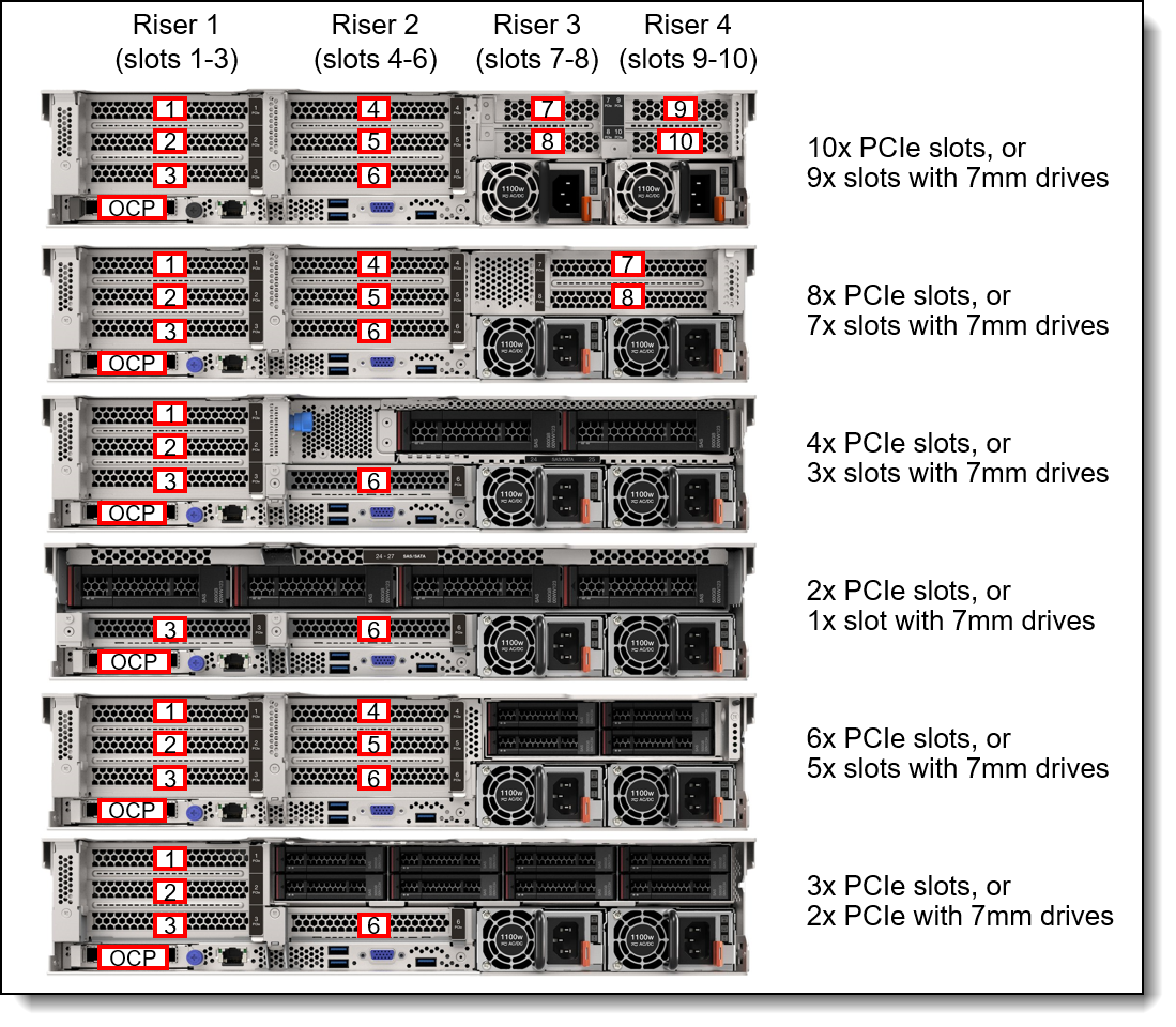
Figure 17. SR650 V3 rear slot configurations
The following figure shows the locations of the front-accessible slots.
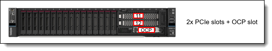
Figure 18. SR650 V3 front slots
Ordering information
The following table lists the riser cards available for CTO builds and for field upgrades. The table includes a Top Choice Express column; for CTO orders, select a TCE component for faster delivery. See the Top Choice section for more information.
No slots: It is also possible to build a configuration without any slots, in which case slot fillers will be derived in the configurator. Slots can be added later as field upgrades using option part numbers as listed in the table.
* All PCIe x8 slots are open ended and will physically support x16 adapters
† In the configurator, when feature BQ2W is selected, BTMS is automatically derived and provides slots 9 & 10. 4XH7A86662 contains both risers. (Note: see the configuration rule below regarding the front drive bay support for 10x rear slots)
Configuration rules:
- For best performance, install PCIe 5.0 adapters in PCIe 5.0 (Gen5) slots
- The server only supports one OCP slot, either in the rear of the server or the front of the server, not both
- The use of Riser 3 is mutually exclusive to onboard NVMe support as they use the same PCIe connectors.
- Only the following drive bay configurations at the front of the server support the use of 10x rear slots (risers 1, 2, 3 and 4). These correspond to storage configs 9, 12, 14, 41, 31, 33, 35, 39, 40. All other configurations may require special bid support.
- 8x 2.5-inch SAS/SATA
- 8x 2.5-inch AnyBay
- 16x 2.5-inch SAS/SATA
- 16x 2.5-inch AnyBay
- If you configure Riser 3 using a x16/x16 FH riser (feature BLL9 or BPKG) with only 1 processor installed, Slot 7 will be connected with x16 lanes, however Slot 8 will not be connected. If you later install the second processor as a field upgrade, you will need to order the necessary cable kit (4X97A82946 or 4X97A82944) to enable Slot 8. See Slot field upgrades for information.
- With only 1 processor installed, Riser 3 can only be enabled using using a x8/x8 FH riser (feature BPKH or BPKF)
- If you want to configure 4x low profile slots for slots 7-10, select feature BQ2W which provides riser 3 (slots 7, 8). Feature BTMS will then be automatically derived to provide riser 4 (slots 9 & 10), along with the necessary cables. Option part number 4XH7A86662 contains both of these risers and the cables.
- The following vRAN processors have fewer PCIe lanes (see the Processor features section) and therefore do not support Riser 3. They are also 1-socket processors, so they also don't support Riser 2. Only Riser 1 and the OCP slot are supported.
- Intel Xeon Gold 5423N 20C 145W 2.1GHz Processor
- Intel Xeon Gold 5433N 20C 160W 2.3GHz Processor
- Intel Xeon Gold 6403N 24C 185W 1.9GHz Processor
- Intel Xeon Gold 6423N 28C 195W 2.0GHz Processor
- Intel Xeon Gold 6433N 32C 205W 2.0GHz Processor
- Intel Xeon Gold 6443N 32C 195W 1.6GHz Processor
- If you want to add both a 7mm drive enclosure plus 2x PCIe slots above it, you will need to order the 7mm drive option (either 4XH7A85898 or 4XH7A85899) plus the x16/x16/E riser kit (4XH7A82900 for PCIe Gen 5 or 4XH7A82892 for Gen 4). The riser kit part number provides the 2-slot riser card.
- All PCIe x8 slots are open ended and will physically support x16 adapters
Serial port
The SR650 V3 optionally supports a RS-232 serial port by adding a COM port bracket to either slot 3 or slot 6. Ordering information is shown in the following table.
Front PCIe slots: The serial port is not supported in the front PCIe slots
| Part number | Feature code | Description | Top Choice Express |
Max quantity |
Slots supported |
|---|---|---|---|---|---|
| 4X97A82921 | BMNJ | ThinkSystem V2/V3 1U COM Port Upgrade Kit | Not TCE | 1 | 3, 6 |
Configuration rules:
- If double-wide GPUs are installed, the serial port is only supported in slot 6 due to a cable length limitation.
The bracket is shown in the following figure. The option part number includes both Low Profile and Full Height brackets.
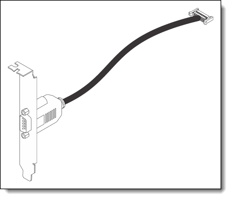
Slot field upgrades
Slot configurations can also be ordered as field upgrades using option part numbers, as listed in the following table.
OCP slot filler
If customers or partners remove an OCP adapter from the server, we recommend that a slot cover (slot filler) be installed in its place to ensure proper airflow in the server. Ordering information is listed in the following table.
Tip: For CTO orders and preconfigured models, slot fillers are automatically installed in slots where an OCP adapter is not installed.
Network adapters
The server has a dedicated OCP 3.0 SFF slot with a PCIe x16 host interface. See Figure 3 for the location of the OCP slot. When located at the rear of the server, the OCP slot operates at PCIe 5.0 speed (once PCIe 5.0 OCP adapters are supported); when located at the front of the server, the OCP slot operates at PCIe 4.0 speed.
The following table lists the supported OCP adapters. The table includes a Top Choice Express column; for CTO orders, select a TCE component for faster delivery. See the Top Choice section for more information.
One port can optionally be shared with the XCC management processor for Wake-on-LAN and NC-SI support. Only 1 OCP card can be installed in the server, either rear-accessible or front-accessible.
The following table lists additional supported network adapters that can be installed in the regular PCIe slots. The table includes a Top Choice Express column; for CTO orders, select a TCE component for faster delivery. See the Top Choice section for more information.
* Field upgrades to add BlueField-3 adapters require a power cable. See below.
‡ Requires a PCIe Gen4 riser; Not supported in a PCIe Gen5 riser
When adding a BlueField-3 adapter as a field upgrade, the power cable listed in the following table will also need to be ordered.
For more information, including the transceivers and cables that each adapter supports, see the list of Lenovo Press Product Guides in the Networking adapters category:
https://lenovopress.com/servers/options/ethernet
Configuration requirements:
- Adapters with a x16 host interface require a x16 slot to maximize performance
- PCIe Gen5 adapters will require a Gen5 riser to maximize performance
- E810 Ethernet and X350 RAID/HBAs: The use of both an Intel E810 network adapter and an X350 HBA/RAID adapter (9350, 5350 and 4350) is supported, however E810 firmware CVL4.3 or later is required. For details, see Support Tip HT513226.
BlueField-2 DPU support
The SR650 V3 supports DPUs for VMware Cloud Foundation using the NVIDIA BlueField-2 Data Processing Unit (DPU). This solution provides zero-trust security and accelerate workloads by improving performance with increased throughput and lower latency by offloading NSX Firewall rules applied at the DPU compute layer thereby making data center applications more efficient.
In addition to these key features, the SR650 V3 now supports up to 2x NVIDIA BlueField-2 Data Processing Units (DPUs) that provides:
- High Availability and Redundancy - Customers can configure the DPUs in an Active-Standby state to enhance redundancy. In this mode, if the active DPU fails, all traffic seamlessly fails over to the standby DPU, ensuring that there is no disruption in service. This configuration is perfect for mission-critical applications where uptime is paramount.
- Enhanced Performance - Both DPUs operate independently, providing maximum throughput. This configuration is ideal for environments where performance is critical, as it takes full advantage of the increased bandwidth with twice the capacity.
Support for BlueField-2 DPUs is available in CTO builds using the following DPU-specific models:
- 7D76CTO4WW and 7D76CTOGWW (3-year warranty)
- 7D75CTO4WW (1-year warranty)
BlueField-3 support: These CTO models are not required for BlueField-3 DPUs.
The DSE solution comprises of two primary components:
- NVIDIA BlueField-2 full-height half-length (FHHL) PCIe adapter (feature BRPK)
- OCP adapter to provide the necessary NC-SI connectivity to the XCC management processor of the server (feature BSH7)
The NVIDIA Bluefield-2 DPU has 8x ARM processor cores, 32GB onboard DDR4 ECC memory, and 2x 25GbE SFP56 ports. The purpose-built hardware-acceleration engines, embedded crypto and secure boot capabilities, and a software stack powered by the NVIDIA DOCA framework provide breakthrough data center performance, efficiency and security for software-defined storage, networking, and management of workloads.
Ordering information is listed in the following table. Both components are required.
* These adapters are only available CTO and only available using DPU-specific CTO model numbers
If you have an existing DPU model with only one DPU installed, you can upgrade to a dual-DPU configuration, using the part numbers listed in the following table. Both the adapter and the NC-SI cable are needed.
Note: The part numbers listed in the table below are not generally orderable. Contact your Lenovo sales representative for ordering information.
Configuration notes:
- The DSE solution requires the OCP adapter; as a result, no other OCP networking adapters are supported
- An additional network adapter is required in addition to the BlueField-2 adapter
- Configurations with 1x DPU require VMware vSphere 8.0 U1 or later
- Configurations with 2x DPUs require VMware vSphere 8.0 U3 or later
- VMware must be preloaded on the server
- Part number 4XC7B02131 is for field upgrades only for the DPU-specific CTO models 7D75CTO4WW and 7D76CTO4WW, where the first DPU is already installed
- Part number 4XC7B02131 is not supported in CTO model 7D76CTOGWW.
GPU adapters
This section describes the supported GPUs.
GPU part numbers
The SR650 V3 supports the following graphics processing units (GPUs). The table includes a Top Choice Express column; for CTO orders, select a TCE component for faster delivery. See the Top Choice section for more information.
* When a double-wide GPU is installed in slot 2, 5 or 7, the adjacent slot 1, 4 and 8 respectively is not available
† Windows Server 2022 does not support more than 16 displays attached to the server
For information about these GPUs, see the ThinkSystem GPU Summary, available at:
https://lenovopress.com/lp0768-thinksystem-thinkagile-gpu-summary
GPU Ready configurations
For CTO orders, the SR650 V3 also supports the selection of a placeholder for a GPU. This selection results in a "GPU ready" configuration which ensures that the server ships with the components needed for GPU installation (GPU power cables, air ducts, power supplies, fans, etc) without actually including the GPUs themselves. The following table lists the ordering information for CTO orders.
Tip: These GPU-Ready feature codes can only be selected with general purpose CTO models such as 7D76CTO1WW. They are not offered in "for AI" models such as 7D76CTOEWW. See the Models section for more information.
Configuration rules
The following configuration requirements must be met when installing GPUs:
- The table includes a Controlled GPU column. If a GPU is listed as Controlled, that means the GPU is not offered in certain markets, as determined by the US Government. If a GPU is listed as No, that means the GPU is not controlled and is available in all markets.
- GPUs can be configured in CTO orders as follows:
- A Controlled GPU can only be configured using one of the Base CTO models designated with "for AI", such as 7D76CTOEWW, as listed in the Models section.
- A GPU that is not controlled can only be configured using one of the Base CTO models that is not named "for AI", such as 7D76CTO1WW, as listed in the Models section.
- All GPUs installed must be identical
- When a double-wide GPU is installed in slot 2, 5 or 7, the adjacent slot 1, 4 and 8 respectively is not available
- Flash storage adapters are not supported.
- Middle drive bays and Rear drive bays are not supported
- 12x 3.5-inch backplanes are not supported
- The following GPUs are not supported with PCIe Gen 5 risers:
- ThinkSystem NVIDIA RTX A400 4GB PCIe Gen4 Active GPU, 4X67B03688
ThinkSystem NVIDIA RTX A1000 8GB PCIe Gen4 Active GPU, 4X67A96431 - ThinkSystem NVIDIA T1000 8GB PCIe Active GPU, 4X67A79777
- ThinkSystem NVIDIA T400 4GB PCIe Active GPU, 4X67A79778
- ThinkSystem NVIDIA RTX A400 4GB PCIe Gen4 Active GPU, 4X67B03688
- Some NVIDIA A Series GPUs are available as two feature codes, one with a CEC chip and one without a CEC chip (ones without the CEC chip have "w/o CEC" in the name). The CEC is a secondary Hardware Root of Trust (RoT) module that provides an additional layer of security, which can be used by customers who have high regulatory requirements or high security standards. NVIDIA uses a multi-layered security model and hence the protection offered by the primary Root of Trust embedded in the GPU is expected to be sufficient for most customers. The CEC defeatured products still offer Secure Boot, Secure Firmware Update, Firmware Rollback Protection, and In-Band Firmware Update Disable. Specifically, without the CEC chip, the GPU does not support Key Revocation or Firmware Attestation. CEC and non-CEC GPUs of the same type of GPU can be mixed in field upgrades.
The server supports up to 3x double-wide GPUs, however due to thermal requirements, GPU support is affected by the front drive bay configuration and by ambient temperature:
- With 16x 2.5-inch front drives bays:
- Up to 3x double-wide GPUs are supported, in slots 2, 5, 7
- For the NVIDIA A40, H100:
- The use of 3x GPUs requires ambient temperature no higher than 25°C
- The use of 2x GPUs (slots 2, 5) requires ambient temperature no higher than 30°C
- All other GPUs: No ambient temperature restrictions-
- With 24x 2.5-inch front drive bays:
- Up to 2x double-wide GPUs are supported, in slots 2, 5
- NVIDIA A40: No support
- All other GPUs: Ambient temperature no higher than 25°C
For additional GPU requirements, see the Thermal rules page in the User Guide:
https://pubs.lenovo.com/sr650-v3/thermal_rules
Riser selections for double-wide GPUs
When a double-wide GPU is installed in slot 2, 5 or 7, the adjacent slot 1, 4 and 8 respectively is not available. The riser cards listed in the following table are used with double-wide GPUs.
GPU Full Length Thermal Option Kit
When installing any full-length GPU as a field upgrade, you will also need to order the GPU Enablement Kit as listed in the following table. This kit is only required for full-length GPUs and is not required for low profile GPUs such as the NVIDIA A2, L4, T1000 and T400.
The following figure shows the GPU air duct with GPU air duct fillers and GPU extend air ducts installed.
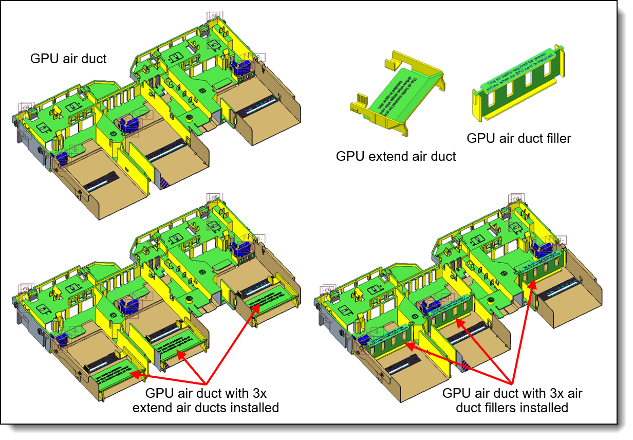
GPU cable kits
The following cable kits are offered to provide auxiliary power cables for GPUs that require one. See the GPU part numbers section to see which GPUs require an auxiliary power cable.
Configuration notes:
- This cable kits are only required for field upgrades; factory (CTO) orders will automatically include any required cables.
- For double-wide GPUs, The DW (double-wide) cable kit is only required if you are adding additional double-wide GPUs to a server that already has a DW GPU installed from a CTO order. If you are doing a field upgrade to install the first DW GPU to a server, order the ThinkSystem SR650 V3 GPU Full Length Thermal Option Kit, 4X67A82883 instead, since 4X67A82883 includes the necessary power cables.
Fibre Channel host bus adapters
The following table lists the Fibre Channel HBAs supported by the SR650 V3.
No Windows 10/11 support: None of the adapters listed in the table are supported with Windows 10 or Windows 11.
For more information, see the list of Lenovo Press Product Guides in the Host bus adapters category:
https://lenovopress.com/servers/options/hba
SAS adapters for external storage
The following table lists SAS HBAs and RAID adapters supported by SR650 V3 server for use with external storage.
No Windows 10/11 support: None of the adapters listed in the table are supported with Windows 10 or Windows 11.
* See below regarding supercap requirements
For a comparison of the functions of the supported storage adapters, see the ThinkSystem RAID Adapter and HBA Reference:
https://lenovopress.lenovo.com/lp1288#sr650-v3-support=SR650%2520V3&internal-or-external-ports=External
The RAID 940-8e adapter uses a flash power module (supercap), which can be installed in one of up to 4 locations in the server depending on the server configuration. See the RAID flash power module (supercap) support section for details. The number of 940-8e RAID adapters supported is based on how many supercaps can be installed in the server. If an internal RAID adapter with flash power modules is installed, the maximum number of 940-8e adapters supported is reduced by 1.
For more information, see the list of Lenovo Press Product Guides in the Host bus adapters and RAID adapters categories:
https://lenovopress.com/servers/options/hba
https://lenovopress.com/servers/options/raid
Cooling
The SR650 V3 server has up to six 60 mm hot-swap variable-speed fans. Five fans are needed when one processor is installed and six fans are required when two processors are installed. Certain 1-processor configurations may also require 6 fans, as described below. The server offers N+1 redundancy. The server also has one or two additional fans integrated in each of the two power supplies.
Depending on the configuration, the server will need either Standard fans (single-rotor 17K RPM) or Performance fans (dual-rotor 21K RPM).
Under the following conditions, Standard fans can be used:
- Processor TDP < 270W
- No 128 GB or 256GB 3DS RDIMMs
- No Persistent memory
- No mid-chassis or rear drive backplanes
- No GPUs
- No low profile slots 7, 8, 9 & 10
- No internal (CFF) HBA/RAID adapter
- A configuration with 24x 2.5" or 12x 3.5" front backplanes and without any following network adapters:
- Any 100Gb, 200Gb or 400Gb adapter
- ThinkSystem Broadcom 57454 10GBASE-T 4-port OCP Ethernet Adapter, 4XC7A08240
- ThinkSystem Broadcom 57416 10GBASE-T 2-port OCP Ethernet Adapter, 4XC7A08236
- ThinkSystem NVIDIA BlueField-2 25GbE SFP56 2-Port PCIe Ethernet DPU w/BMC & Crypto, BRPK
- Not the following configurations:
- 12x 3.5-inch front drive bays with an OCP adapter installed
- Ambient temperature 35°C or lower
If any conditions are not met, Performance fans are required.
The quantity of fans required are as follows:
- 6 fans:
- 2 processor configurations
- 1 processor configurations with middle drive backplanes
- 1 processor configurations with rear drive backplanes
- 1 processor configurations with Riser 3
- 5 fans:
- 1 processor configuration without middle/rear drive backplanes or Riser 3
Ordering information for the fans is listed in the following table.
Power supplies
The SR650 V3 supports up to two redundant hot-swap power supplies.
- Power supply ordering information
- Power supply LEDs
- Power cords (C13 connectors)
- Power cords (C19 connectors)
- -48V DC power cord
Power supply ordering information
The power supply choices are listed in the following table. Both power supplies used in server must be identical.
Tip: When configuring a server in the DCSC configurator, power consumption is calculated precisely by interfacing with Lenovo Capacity Planner. You can therefore select the appropriate power supply for your configuration. However, do consider future upgrades that may require additional power needs.
Supported power supplies are auto-sensing dual-voltage units, supporting both 110V AC (100-127V 50/60 Hz) and 220V AC (200-240V 50/60 Hz) power. For China customers, all power supplies support 240V DC.
AC power supplies up to 1800W have a C14 connector. AC power supplies 2400W and above have a C20 connector. Power supply options do not include a line cord. For server configurations, the inclusion of a power cord is model dependent. Configure-to-order models can be configured without power cords if desired.
The ThinkSystem 1100W -48V DC Hot-Swap Gen2 Power Supply v2 (4P57A89415) has a Weidmuller TOP 4GS/3 7.6 terminal as shown in the following figure. The ThinkSystem 1100W -48V DC Hot-Swap Gen2 Power Supply (4P57A26296) has the same connector type.
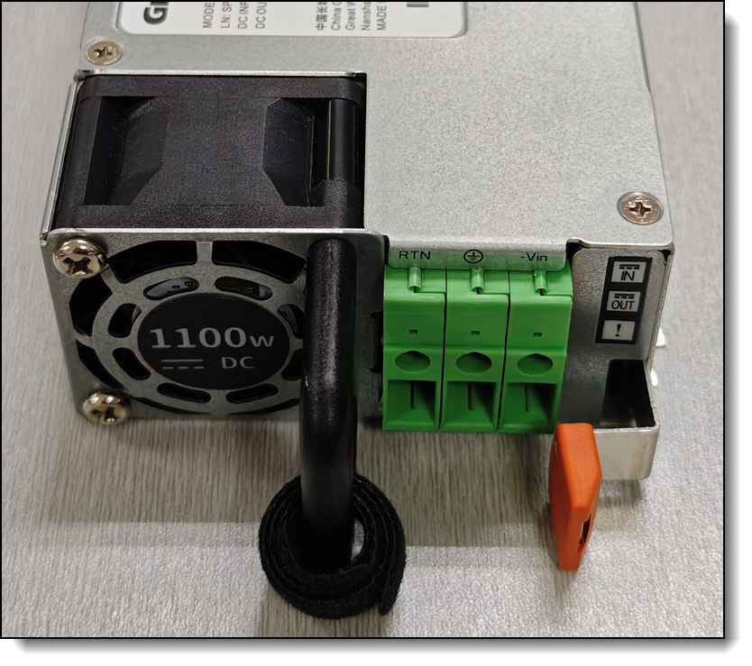
Figure 21. Connector on the ThinkSystem 1100W -48V DC Hot-Swap Gen2 Power Supply v2 (4P57A89415)
Power supply LEDs
The supported hot-swap power supplies have the following LEDs:
- Power input LED:
- Green: The power supply is connected to the AC power source
- Off: The power supply is disconnected from the AC power source or a power problem has occurred
- Power output LED:
- Green: The server is on and the power supply is working normally
- Blinking green: The power supply is in Zero-output/Standby mode (see below)
- Off: The server is powered off, or the power supply is not working properly
- Power supply error LED:
- Off: The power supply is working normally
- Yellow: The power supply has failed
Power cords (C13 connectors)
Line cords and rack power cables with C13 connectors can be ordered as listed in the following table.
115V customers: If you plan to use the 1100W power supply with a low-range (100-127V) power source, select a power cable that is rated above 10A. Power cables that are rated at 10A or below are not supported with low-range power.
Power cords (C19 connectors)
Line cords and rack power cables with C19 connectors can be ordered as listed in the following table.
Systems management
The SR650 V3 contains an integrated service processor, XClarity Controller 2 (XCC2), which provides advanced control, monitoring, and alerting functions. The XCC2 is based on the AST2600 baseboard management controller (BMC) using a dual-core ARM Cortex A7 32-bit RISC service processor running at 1.2 GHz.
Topics in this section:
System I/O Board
The SR650 V3 implements a separate System I/O Board that connects to the Processor Board. The location of the System I/O Board is shown in the Components and connectors section. The System I/O Board contains all the connectors visible at the rear of the server as shown in the following figure.
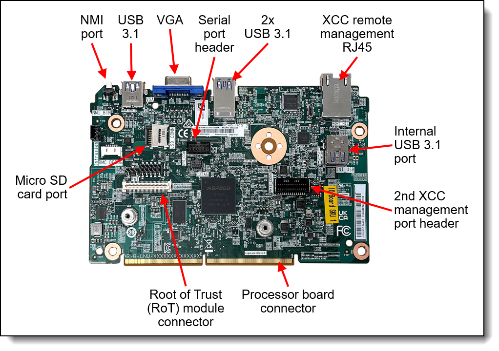
The board also has the following components:
- XClarity Controller 2, implemented using the ASPEED AST2600 baseboard management controller (BMC).
- Root of Trust (RoT) module - a daughter card that implements Platform Firmware Resiliency (PFR) hardware Root of Trust (RoT) which enables the server to be NIST SP800-193 compliant. For more details about PFR, see the Security section.
- Connector to enable an additional redundant Ethernet connection to the XCC2 controller. The connector is used in conjunction with the ThinkSystem V3 Management NIC Adapter Kit (4XC7A85319). For details, see the Remote management section.
- Internal USB port - to allow the booting of an operating system from a USB key. The VMware ESXi preloads use this port for example. Preloads are described in the Operating system support section.
- MicroSD card port to enable the use of a MicroSD card for additional storage for use with the XCC2 controller. XCC2 can use the storage as a Remote Disc on Card (RDOC) device (up to 4GB of storage). It can also be used to store firmware updates (including N-1 firmware history) for ease of deployment.
Tip: Without a MicroSD card installed, the XCC2 controller will have 100MB of available RDOC storage.
Ordering information for the supported USB drive and Micro SD card are listed in the following table.
Local management
The SR650 V3 offers a front operator panel with key LED status indicators, as shown in the following figure.
Tip: The Network LED only shows network activity of the installed OCP network adapter.
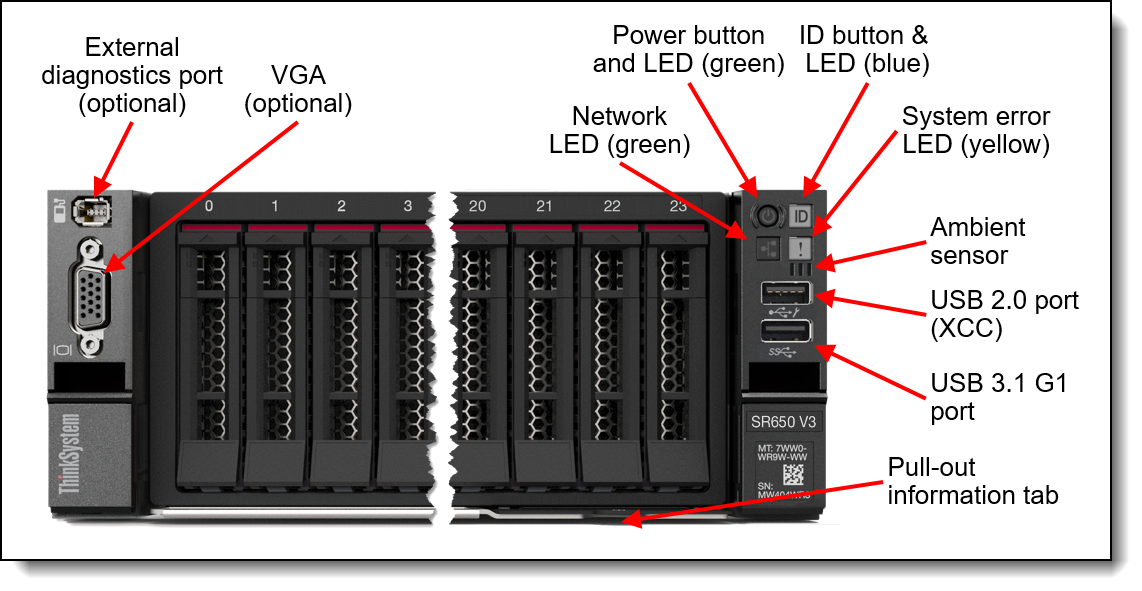
Figure 23. Front operator controls are on the left and right side of the server
Light path diagnostics
The server offers light path diagnostics. If an environmental condition exceeds a threshold or if a system component fails, XCC lights LEDs inside the server to help you diagnose the problem and find the failing part. The server has fault LEDs next to the following components:
- Each memory DIMM
- Each drive bay
- Each power supply
Front VGA and External Diagnostics ports
The VGA port at the rear of the server is included in all models, however the VGA port at the front of the server is optional. When the front VGA is in use, the rear VGA port is automatically disabled.
Also optional is the External Diagnostics port which enables the use of the External Diagnostics Handset, described in the next section.
To configure either the VGA port or the External Diagnostics port at the front of the server, select one of the following feature codes when configuring the server.
External Diagnostics Handset
The SR650 V3 optionally has a port to connect an External Diagnostics Handset as described in the preceding section. The External Diagnostics Handset has the same functions as the Integrated Diagnostics Panel but has the advantages of not consuming space on the front of the server plus it can be shared among many servers in your data center. The handset has a magnet on the back of it to allow you to easily mount it on a convenient place on any rack cabinet.
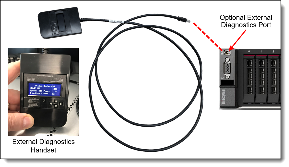
Figure 24. External Diagnostics Handset
Ordering information for the External Diagnostics Handset with is listed in the following table.
| Part number | Feature code | Description | Top Choice Express |
|---|---|---|---|
| 4TA7A64874 | BEUX | ThinkSystem External Diagnostics Handset | Not TCE |
Integrated Diagnostics Panel for 8x 2.5-inch and 16x 2.5-inch drive bay configurations
For configurations with 8x 2.5-inch or 16x 2.5-inch drive bays at the front, the server can optionally be configured to have a pull-out Integrated Diagnostics Panel. The following figure shows the standard (fixed) operator panel and the optional Integrated Diagnostics Panel.
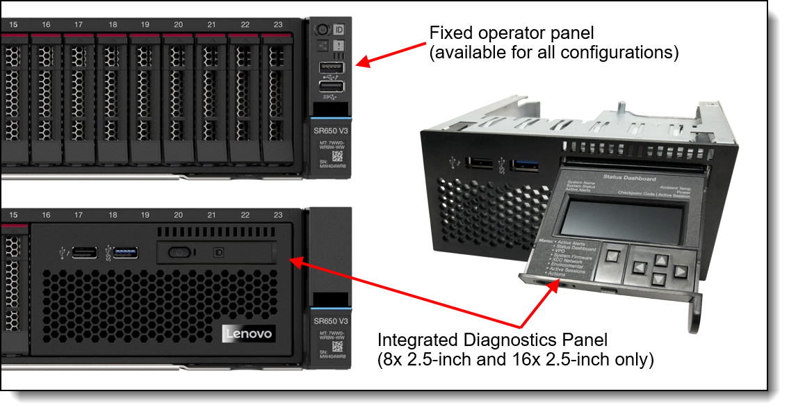
Figure 25. Operator panel choices for the 8x 2.5-inch drive bay configuration
The Integrated Diagnostics Panel allows quick access to system status, firmware, network, and health information. The LCD display on the panel and the function buttons give you access to the following information:
- Active alerts
- Status Dashboard
- System VPD: machine type & mode, serial number, UUID string
- System firmware levels: UEFI and XCC firmware
- XCC network information: hostname, MAC address, IP address, DNS addresses
- Environmental data: Ambient temperature, CPU temperature, AC input voltage, estimated power consumption
- Active XCC sessions
- System reset action
The Integrated Diagnostics Panel can be configured as listed in the following table. It is only available configure-to-order (CTO); not available as a field upgrade.
Information pull-out tab
The front of the server also houses an information pull-out tab (also known as the network access tag). See Figure 2 for the location. A label on the tab shows the network information (MAC address and other data) to remotely access the service processor.
System status with XClarity Mobile
The XClarity Mobile app includes a tethering function where you can connect your Android or iOS device to the server via USB to see the status of the server.
The steps to connect the mobile device are as follows:
- Enable USB Management on the server, by holding down the ID button for 3 seconds (or pressing the dedicated USB management button if one is present)
- Connect the mobile device via a USB cable to the server's USB port with the management symbol

- In iOS or Android settings, enable Personal Hotspot or USB Tethering
- Launch the Lenovo XClarity Mobile app
Once connected you can see the following information:
- Server status including error logs (read only, no login required)
- Server management functions (XClarity login credentials required)
Remote management
The server offers a dedicated RJ45 port at the rear of the server for remote management via the XClarity Controller management processor. The port supports 10/100/1000 Mbps speeds.
Remote server management is provided through industry-standard interfaces:
- Intelligent Platform Management Interface (IPMI) Version 2.0
- Simple Network Management Protocol (SNMP) Version 3 (no SET commands; no SNMP v1)
- Common Information Model (CIM-XML)
- Representational State Transfer (REST) support
- Redfish support (DMTF compliant)
- Web browser - HTML 5-based browser interface (Java and ActiveX not required) using a responsive design (content optimized for device being used - laptop, tablet, phone) with NLS support
The SR650 V3 also supports the use of an OCP adapter that provides an additional redundant Ethernet connection to the XCC2 controller. Ordering information is listed in the following table.
| Part number |
Feature code |
Description | Top Choice Express |
Maximum quantity |
|---|---|---|---|---|
| 4XC7A85319 | BTMQ | ThinkSystem V3 Management NIC Adapter Kit | Not TCE | 1 |
The use of this adapter allows concurrent remote access using both the connection on the adapter and the onboard RJ45 remote management port provided by the server. The adapter and onboard port have separate IP addresses.
Configuration rules:
- The Redundant System Management Port Adapter is installed in the OCP adapter slot at the rear of the server and is mutually exclusive with any OCP network adapter.
- It is not supported installed in the front OCP slot (if the front OCP slot is configured)
- If the Redundant System Management Port Adapter is installed in the rear slot, then the front OCP slot (if configured) cannot be used.
The following figure shows the server with the Redundant System Management Port Adapter installed in the OCP slot.
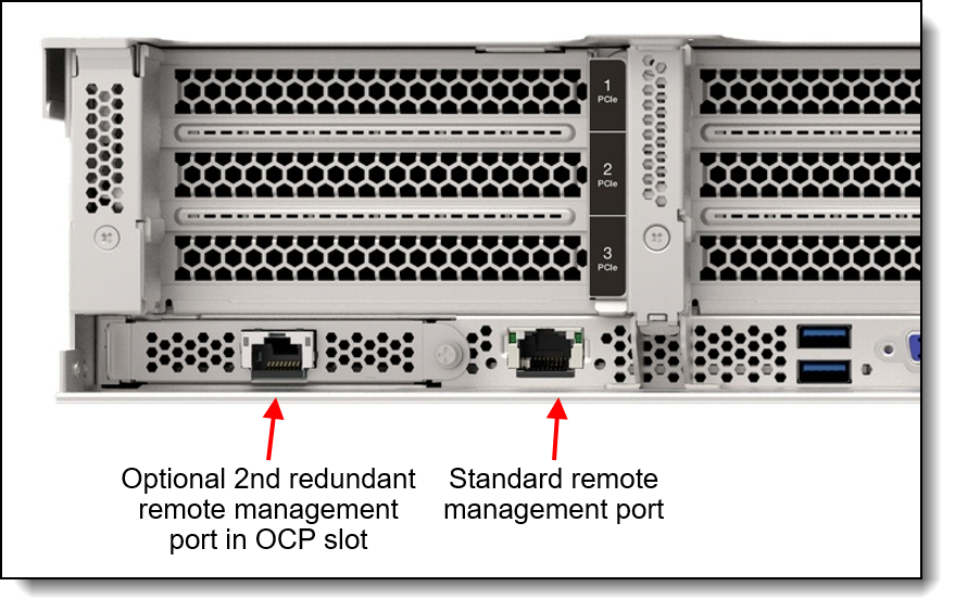
Figure 26. SR650 V3 with the Redundant System Management Port Adapter installed
IPMI via the Ethernet port (IPMI over LAN) is supported, however it is disabled by default. For CTO orders you can specify whether you want to the feature enabled or disabled in the factory, using the feature codes listed in the following table.
XCC2 Platinum
The XCC2 service processor in the SR650 V3 supports an upgrade to the Platinum level of features. Compared to the XCC functions of ThinkSystem V2 and earlier systems, Platinum adds the same features as Enterprise and Advanced levels in ThinkSystem V2, plus additional features.
XCC2 Platinum adds the following Enterprise and Advanced functions:
- Remotely viewing video with graphics resolutions up to 1600x1200 at 75 Hz with up to 23 bits per pixel, regardless of the system state
- Remotely accessing the server using the keyboard and mouse from a remote client
- International keyboard mapping support
- Syslog alerting
- Redirecting serial console via SSH
- Component replacement log (Maintenance History log)
- Access restriction (IP address blocking)
- Lenovo SED security key management
- Displaying graphics for real-time and historical power usage data and temperature
- Boot video capture and crash video capture
- Virtual console collaboration - Ability for up to 6 remote users to be log into the remote session simultaneously
- Remote console Java client
- Mapping the ISO and image files located on the local client as virtual drives for use by the server
- Mounting the remote ISO and image files via HTTPS, SFTP, CIFS, and NFS
- Power capping
- System utilization data and graphic view
- Single sign on with Lenovo XClarity Administrator
- Update firmware from a repository
- License for XClarity Energy Manager
XCC2 Platinum also adds the following features that are new to XCC2:
- System Guard - Monitor hardware inventory for unexpected component changes, and simply log the event or prevent booting
- Enterprise Strict Security mode - Enforces CNSA 1.0 level security
- Neighbor Group - Enables administrators to manage and synchronize configurations and firmware level across multiple servers
Ordering information is listed in the following table. XCC2 Platinum is a software license upgrade - no additional hardware is required.
With XCC2 Platinum, for CTO orders, you can request that System Guard be enabled in the factory and the first configuration snapshot be recorded. To add this to an order, select feature code listed in the following table. The selection is made in the Security tab of the DCSC configurator.
| Feature code | Description | Top Choice Express |
|---|---|---|
| BUT2 | Install System Guard | Not TCE |
For more information about System Guard, see https://pubs.lenovo.com/xcc2/NN1ia_c_systemguard
Lenovo XClarity Provisioning Manager
Lenovo XClarity Provisioning Manager (LXPM) is a UEFI-based application embedded in ThinkSystem servers and accessible via the F1 key during system boot.
LXPM provides the following functions:
- Graphical UEFI Setup
- System inventory information and VPD update
- System firmware updates (UEFI and XCC)
- RAID setup wizard
- OS installation wizard (including unattended OS installation)
- Diagnostics functions
Lenovo XClarity One is a cloud-native unified Management-as-a-Service (MaaS) platform, engineered to modernize IT infrastructure. .
XClarity One is the next milestone in Lenovo’s portfolio of systems management products. Now you can leverage the benefits of a true next-generation platform for the deployment, management, and maintenance of your infrastructure through a single, centralized platform that delivers a consistent user experience across all Lenovo products.
XClarity One's primary architectural value is divided into three key areas:
- How it predicts issues (AI/Analytics)
- How it securely connects (Secure Management Hubs),
- How it actually configures the hardware at scale (Template-Driven Lifecycle Control)
AI-powered Automation
XClarity One harnesses the power of AI and predictive analytics to enhance the performance and reliability of your infrastructure with proactive protection.
- AI-Powered Predictive Failure Analytics - XC1 utilizes machine learning infrastructure to look at live device telemetries. The platform securely collects memory-diagnostic logs and pushes them into an active MPFA AI model infrastructure to analyze health patterns and predict probable hardware degradation before it manifests as a hard failure.
- AI-Powered Call-Home - A Call-Home serviceable event opens a support ticket automatically, leveraging AI technology (in the case of MPFA) for problem determination and fast resolution automatically dispatching parts and services, reducing service costs and minimizing downtime.
Secure Management Hub
Lenovo’s proprietary Management Hub is an on-premises virtual appliance that acts as the bridge between your infrastructure and the cloud.
- On-Premises Security with Cloud Flexibility - your infrastructure has no direct connection to the cloud, greatly reducing your attack surface from external threats while still having the deployment benefits, flexibility, and scalability of a cloud solution.
- Authentication and Authorization - built on a Zero Trust Architecture and requiring OTP Application authentication for all users to handle the support of all customers’ servers and client devices. Role-based access controls help define and restrict permissions based on user roles.
Template-Driven Lifecycle Control
Lenovo’s unified management model eliminates fragmented server administration, allowing you to deploy, track, and maintain your entire infrastructure fleet from a single cloud-native dashboard.
- Automated Configuration and Compliance: Leverage scalable, repeatable device templates to rapidly deploy firmware updates, operating systems, and core baseboard management controller (BMC/UEFI) simultaneously across multiple sites. XClarity One continuously analyzes hardware compliance, shifting out-of-compliance systems to a critical status until a template re-deployment aligns them back to corporate standards.
- Global Asset Visibility and Fleet Telemetry: Centralize real-time tracking of component health, warranty status, and comprehensive hardware inventories. The platform aggregates live usage data, including memory allocation, power consumption, and processor thermal trends, giving you total operational awareness whether a server resides in a centralized data center or a remote edge environment.
Centralized management via Lenovo XClarity One can be integrated into your environment as an optional component. License information for XClarity One is listed in the following table.
Licensing notes:
- One license is needed per physical managed device.
- Starter license is functionally identical to Standard license but is limited to 10 devices per organization maximum.
For more information, see these resources:
- Lenovo XClarity One datasheet:
https://lenovopress.lenovo.com/ds0188-lenovo-xclarity-one - Lenovo XClarity One product guide:
https://lenovopress.lenovo.com/lp1992-lenovo-xclarity-one - Migrating to Lenovo XClarity One: An Overview:
https://lenovopress.lenovo.com/lp2429-migrating-to-lenovo-xclarity-one-an-overview
Lenovo XClarity Administrator
Lenovo XClarity Administrator is a centralized resource management solution designed to reduce complexity, speed response, and enhance the availability of Lenovo systems and solutions. It provides agent-free hardware management for ThinkSystem servers. The administration dashboard is based on HTML 5 and allows fast location of resources so tasks can be run quickly.
Because Lenovo XClarity Administrator does not require any agent software to be installed on the managed endpoints, there are no CPU cycles spent on agent execution, and no memory is used, which means that up to 1GB of RAM and 1 - 2% CPU usage is saved, compared to a typical managed system where an agent is required.
Lenovo XClarity Administrator is an optional software component for the SR650 V3. The software can be downloaded and used at no charge to discover and monitor the SR650 V3 and to manage firmware upgrades.
If software support is required for Lenovo XClarity Administrator, or premium features such as configuration management and operating system deployment are required, Lenovo XClarity Pro software subscription should be ordered. Lenovo XClarity Pro is licensed on a per managed system basis, that is, each managed Lenovo system requires a license.
The following table lists the Lenovo XClarity software license options.
Lenovo XClarity Administrator offers the following standard features that are available at no charge:
- Auto-discovery and monitoring of Lenovo systems
- Firmware updates and compliance enforcement
- External alerts and notifications via SNMP traps, syslog remote logging, and e-mail
- Secure connections to managed endpoints
- NIST 800-131A or FIPS 140-3 compliant cryptographic standards between the management solution and managed endpoints
- Integration into existing higher-level management systems such as cloud automation and orchestration tools through REST APIs, providing extensive external visibility and control over hardware resources
- An intuitive, easy-to-use GUI
- Scripting with Windows PowerShell, providing command-line visibility and control over hardware resources
Lenovo XClarity Administrator offers the following premium features that require an optional Pro license:
- Pattern-based configuration management that allows to define configurations once and apply repeatedly without errors when deploying new servers or redeploying existing servers without disrupting the fabric
- Bare-metal deployment of operating systems and hypervisors to streamline infrastructure provisioning
For more information, refer to the Lenovo XClarity Administrator Product Guide:
http://lenovopress.com/tips1200
Lenovo XClarity Integrators
Lenovo also offers software plug-in modules, Lenovo XClarity Integrators, to manage physical infrastructure from leading external virtualization management software tools including those from Microsoft and VMware.
These integrators are offered at no charge, however if software support is required, a Lenovo XClarity Pro software subscription license should be ordered.
Lenovo XClarity Integrators offer the following additional features:
- Ability to discover, manage, and monitor Lenovo server hardware from VMware vCenter or Microsoft System Center
- Deployment of firmware updates and configuration patterns to Lenovo x86 rack servers and Flex System from the virtualization management tool
- Non-disruptive server maintenance in clustered environments that reduces workload downtime by dynamically migrating workloads from affected hosts during rolling server updates or reboots
- Greater service level uptime and assurance in clustered environments during unplanned hardware events by dynamically triggering workload migration from impacted hosts when impending hardware failures are predicted
For more information about all the available Lenovo XClarity Integrators, see the Lenovo XClarity Administrator Product Guide: https://lenovopress.com/tips1200-lenovo-xclarity-administrator
Lenovo XClarity Essentials
Lenovo offers the following XClarity Essentials software tools that can help you set up, use, and maintain the server at no additional cost:
- Lenovo Essentials OneCLI
OneCLI is a collection of server management tools that uses a command line interface program to manage firmware, hardware, and operating systems. It provides functions to collect full system health information (including health status), configure system settings, and update system firmware and drivers.
- Lenovo Essentials UpdateXpress
The UpdateXpress tool is a standalone GUI application for firmware and device driver updates that enables you to maintain your server firmware and device drivers up-to-date and help you avoid unnecessary server outages. The tool acquires and deploys individual updates and UpdateXpress System Packs (UXSPs) which are integration-tested bundles.
- Lenovo Essentials Bootable Media Creator
The Bootable Media Creator (BOMC) tool is used to create bootable media for offline firmware update.
For more information and downloads, visit the Lenovo XClarity Essentials web page:
http://support.lenovo.com/us/en/documents/LNVO-center
Lenovo XClarity Energy Manager
Lenovo XClarity Energy Manager (LXEM) is a power and temperature management solution for data centers. It is an agent-free, web-based console that enables you to monitor and manage power consumption and temperature in your data center through the management console. It enables server density and data center capacity to be increased through the use of power capping.
LXEM is a licensed product. A single-node LXEM license is included with the XClarity Controller Platinum upgrade as described in the XCC2 Platinum section. If your server does not have the XCC Platinum upgrade, Energy Manager licenses can be ordered as shown in the following table.
| Part number | Description |
|---|---|
| 4L40E51621 | Lenovo XClarity Energy Manager Node License (1 license needed per server) |
For more information about XClarity Energy Manager, see the following resources:
- Lenovo Support page:
https://datacentersupport.lenovo.com/us/en/solutions/lnvo-lxem - User Guide for XClarity Energy Manager:
https://pubs.lenovo.com/lxem/
Lenovo Capacity Planner
Lenovo Capacity Planner is a power consumption evaluation tool that enhances data center planning by enabling IT administrators and pre-sales professionals to understand various power characteristics of racks, servers, and other devices. Capacity Planner can dynamically calculate the power consumption, current, British Thermal Unit (BTU), and volt-ampere (VA) rating at the rack level, improving the planning efficiency for large scale deployments.
For more information, refer to the Capacity Planner web page:
http://datacentersupport.lenovo.com/us/en/solutions/lnvo-lcp
Security
Topics in this section:
Security features
The SR650 V3 server offers the following electronic security features:
- Secure Boot function of the Intel Xeon processor
- Support for Platform Firmware Resiliency (PFR) hardware Root of Trust (RoT) - see the Platform Firmware Resiliency section
- Firmware signature processes compliant with FIPS and NIST requirements
- System Guard (part of XCC Platinum) - Proactive monitoring of hardware inventory for unexpected component changes
- Administrator and power-on password
- Integrated Trusted Platform Module (TPM) supporting TPM 2.0
- Self-encrypting drives (SEDs) with support for enterprise key managers - see the SED encryption key management section
The server is NIST SP 800-147B compliant.
The SR650 V3 server also offers the following physical security features:
- Optional chassis intrusion switch
- Optional lockable front security bezel
The optional lockable front security bezel is shown in the following figure and includes a key that enables you to secure the bezel over the drives and system controls thereby reducing the chance of unauthorized or accidental access to the server.
Front PCIe slots: The use of the security bezel is not supported when the server has front PCIe slots.
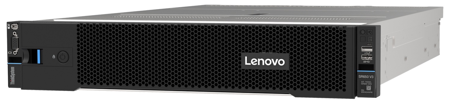
Figure 27. Lockable front security bezel
The dimensions of the security bezel are:
- Width: 437 mm (17.2 in.)
- Height: 87 mm (3.4 in.)
- Width: 23 mm (0.9 in.)
The following table lists the security options for the SR650 V3.
Tip: The only difference between security bezels 4XH7A09886 and 4XH7A90300 is the Lenovo logo: On 4XH7A09886, the logo is made from plastic; on 4XH7A90300, the logo is made from aluminum alloy.
Platform Firmware Resiliency - Lenovo ThinkShield
Lenovo's ThinkShield Security is a transparent and comprehensive approach to security that extends to all dimensions of our data center products: from development, to supply chain, and through the entire product lifecycle.
The ThinkSystem SR650 V3 includes Platform Firmware Resiliency (PFR) hardware Root of Trust (RoT) which enables the system to be NIST SP800-193 compliant. This offering further enhances key platform subsystem protections against unauthorized firmware updates and corruption, to restore firmware to an integral state, and to closely monitor firmware for possible compromise from cyber-attacks.
PFR operates upon the following server components:
- UEFI image – the low-level server firmware that connects the operating system to the server hardware
- XCC image – the management “engine” software that controls and reports on the server status separate from the server operating system
- FPGA image – the code that runs the server’s lowest level hardware controller on the motherboard
The Lenovo Platform Root of Trust Hardware performs the following three main functions:
- Detection – Measures the firmware and updates for authenticity
- Recovery – Recovers a corrupted image to a known-safe image
- Protection – Monitors the system to ensure the known-good firmware is not maliciously written
These enhanced protection capabilities are implemented using a dedicated, discrete security processor whose implementation has been rigorously validated by leading third-party security firms. Security evaluation results and design details are available for customer review – providing unprecedented transparency and assurance.
The SR650 V3 includes support for Secure Boot, a UEFI firmware security feature developed by the UEFI Consortium that ensures only immutable and signed software are loaded during the boot time. The use of Secure Boot helps prevent malicious code from being loaded and helps prevent attacks, such as the installation of rootkits. Lenovo offers the capability to enable secure boot in the factory, to ensure end-to-end protection. Alternatively, Secure Boot can be left disabled in the factory, allowing the customer to enable it themselves at a later point, if desired.
The following table lists the relevant feature code(s).
Tip: If Secure Boot is not enabled in the factory, it can be enabled later by the customer. However once Secure Boot is enabled, it cannot be disabled.
Intel Transparent Supply Chain
Add a layer of protection in your data center and have peace of mind that the server hardware you bring into it is safe authentic and with documented, testable, and provable origin.
Lenovo has one of the world’s best supply chains, as ranked by Gartner Group, backed by extensive and mature supply chain security programs that exceed industry norms and US Government standards. Now we are the first Tier 1 manufacturer to offer Intel® Transparent Supply Chain in partnership with Intel, offering you an unprecedented degree of supply chain transparency and assurance.
To enable Intel Transparent Supply Chain for the Intel-based servers in your order, add the following feature code in the DCSC configurator, under the Security tab.
| Feature code | Description |
|---|---|
| BB0P | Intel Transparent Supply Chain |
For more information on this offering, see the paper Introduction to Intel Transparent Supply Chain on Lenovo ThinkSystem Servers, available from https://lenovopress.com/lp1434-introduction-to-intel-transparent-supply-chain-on-thinksystem-servers.
Security standards
The SR650 V3 supports the following security standards and capabilities:
- Industry Standard Security Capabilities
- Intel CPU Enablement
- AES-NI (Advanced Encryption Standard New Instructions)
- CBnT (Converged Boot Guard and Trusted Execution Technology)
- CET (Control flow Enforcement Technology)
- Hardware-based side channel attack resilience enhancements
- MKTME/TME (Multi-Key Total Memory Encryption)
- SGX (Software Guard eXtensions)
- SGX-TEM (Trusted Environment Mode)
- TDX (Trust Domain Extensions)
- TXT (Trusted eXecution Technology)
- VT (Virtualization Technology)
- XD (eXecute Disable)
- Microsoft Windows Security Enablement
- Credential Guard
- Device Guard
- Host Guardian Service
- TPM 2.0 (Trusted Platform Module 2.0)
- UEFI (Unified Extensible Firmware Interface) Forum Secure Boot
- Intel CPU Enablement
- Hardware Root of Trust and Security
- Independent security subsystem providing platform-wide NIST SP800-193 compliant Platform Firmware Resilience (PFR)
- Management domain RoT provided by the Secure Boot feature of the AST2600 Baseboard Management Controller (BMC)
- Platform Security
- Boot and run-time firmware integrity monitoring with rollback to known-good firmware (e.g., “self-healing”)
- Non-volatile storage bus security monitoring and filtering
- Resilient firmware implementation, such as to detect and defeat unauthorized flash writes or SMM (System Management Mode) memory incursions
- Patented IPMI KCS channel privileged access authorization (USPTO Patent# 11,256,810)
- Host and management domain authorization, including integration with CyberArk for enterprise password management
- KMIP (Key Management Interoperability Protocol) compliant, including support for IBM SKLM and Thales KeySecure
- Reduced “out of box” attack surface
- Configurable network services
- FIPS 140-3 (in progress) validated cryptography for XCC
- CNSA Suite 1.0 Quantum-resistant cryptography for XCC
- Lenovo System Guard
For more information on platform security, see the paper “How to Harden the Security of your ThinkSystem Server and Management Applications” available from https://lenovopress.com/lp1260-how-to-harden-the-security-of-your-thinksystem-server.
- Standards Compliance and/or Support
- NIST SP800-131A rev 2 “Transitioning the Use of Cryptographic Algorithms and Key Lengths”
- NIST SP800-147B “BIOS Protection Guidelines for Servers”
- NIST SP800-193 “Platform Firmware Resiliency Guidelines”
- ISO/IEC 11889 “Trusted Platform Module Library”
- Common Criteria TCG Protection Profile for “PC Client Specific TPM 2.0”
- European Union Commission Regulation 2019/424 (“ErP Lot 9”) “Ecodesign Requirements for Servers and Data Storage Products” Secure Data Deletion
- Optional FIPS 140-2 validated Self-Encrypting Disks (SEDs) with external KMIP-based key management
- Product and Supply Chain Security
- Suppliers validated through Lenovo’s Trusted Supplier Program
- Developed in accordance with Lenovo’s Secure Development Lifecycle (LSDL)
- Continuous firmware security validation through automated testing, including static code analysis, dynamic network and web vulnerability testing, software composition analysis, and subsystem-specific testing, such as UEFI security configuration validation
- Ongoing security reviews by US-based security experts, with attestation letters available from our third-party security partners
- Digitally signed firmware, stored and built on US-based infrastructure and signed on US-based Hardware Security Modules (HSMs)
- Manufacturing transparency via Intel Transparent Supply Chain (for details, see https://lenovopress.com/lp1434-introduction-to-intel-transparent-supply-chain-on-lenovo-thinksystem-servers)
- TAA (Trade Agreements Act) compliant manufacturing, by default in Mexico for North American markets with additional US and EU manufacturing options
- US 2019 NDAA (National Defense Authorization Act) Section 889 compliant
Rack installation
The following table lists the rack installation options that are available for the SR650 V3.
* The Enhanced Slide Rail Kits are used when the server is shipped in a rack and the server is 34 kg or heavier (configuration with 20x 3.5-inch HDDs for example)
For the specification of the rail kits, see the ThinkSystem and ThinkEdge Rail Kit Reference:
https://lenovopress.lenovo.com/lp1838-thinksystem-and-thinkedge-rail-kit-reference#sr650-v3-support=SR650%2520V3
Operating system support
The SR650 V3 with 5th Gen Intel Xeon Scalable processors supports the following operating systems:
- Microsoft Windows 10 (x64)
- Microsoft Windows 11
- Microsoft Windows Server 2019
- Microsoft Windows Server 2022
- Microsoft Windows Server 2025
- Red Hat Enterprise Linux 8.8
- Red Hat Enterprise Linux 8.9
- Red Hat Enterprise Linux 8.10
- Red Hat Enterprise Linux 9.2
- Red Hat Enterprise Linux 9.3
- Red Hat Enterprise Linux 9.4
- Red Hat Enterprise Linux 9.5
- Red Hat Enterprise Linux 9.6
- Red Hat Enterprise Linux 9.7
- Red Hat Enterprise Linux 9.8
- Red Hat Enterprise Linux 10.0
- Red Hat Enterprise Linux 10.1
- Red Hat Enterprise Linux 10.2
- SUSE Linux Enterprise Server 15 SP5
- SUSE Linux Enterprise Server 15 SP6
- SUSE Linux Enterprise Server 15 SP7
- SUSE Linux Enterprise Server 15 Xen SP5
- SUSE Linux Enterprise Server 16
- Ubuntu 20.04 LTS 64-bit
- Ubuntu 22.04 LTS 64-bit
- Ubuntu 24.04 LTS 64-bit
- VMware ESXi 7.0 U3
- VMware ESXi 8.0 U2
- VMware ESXi 8.0 U3
- VMware ESXi 9.0
- VMware ESXi 9.1
The SR650 V3 with 4th Gen Intel Xeon Scalable processors supports the following operating systems:
- Microsoft Windows 10 (x64)
- Microsoft Windows 11
- Microsoft Windows Server 2019
- Microsoft Windows Server 2022
- Microsoft Windows Server 2025
- Red Hat Enterprise Linux 8.6
- Red Hat Enterprise Linux 8.7
- Red Hat Enterprise Linux 8.8
- Red Hat Enterprise Linux 8.9
- Red Hat Enterprise Linux 8.10
- Red Hat Enterprise Linux 9.0
- Red Hat Enterprise Linux 9.1
- Red Hat Enterprise Linux 9.2
- Red Hat Enterprise Linux 9.3
- Red Hat Enterprise Linux 9.4
- Red Hat Enterprise Linux 9.5
- Red Hat Enterprise Linux 9.6
- Red Hat Enterprise Linux 9.7
- Red Hat Enterprise Linux 9.8
- Red Hat Enterprise Linux 10.0
- Red Hat Enterprise Linux 10.1
- Red Hat Enterprise Linux 10.2
- SUSE Linux Enterprise Server 15 SP4
- SUSE Linux Enterprise Server 15 SP5
- SUSE Linux Enterprise Server 15 SP6
- SUSE Linux Enterprise Server 15 SP7
- SUSE Linux Enterprise Server 15 Xen SP4
- SUSE Linux Enterprise Server 15 Xen SP5
- SUSE Linux Enterprise Server 16
- Ubuntu 20.04 LTS 64-bit
- Ubuntu 22.04 LTS 64-bit
- Ubuntu 24.04 LTS 64-bit
- VMware ESXi 7.0 U3
- VMware ESXi 8.0
- VMware ESXi 8.0 U1
- VMware ESXi 8.0 U2
- VMware ESXi 8.0 U3
- VMware ESXi 9.0
- VMware ESXi 9.1
The SR650 V3 also supports VMware vSphere Distributed Services Engine (DSE) with the NVIDIA Bluefield-2 SmartNIC Data Processing Unit (DPU) adapter. See the DPU adapter section for more information.
For a complete list of supported, certified and tested operating systems, plus additional details and links to relevant web sites, see the Operating System Interoperability Guide: https://lenovopress.lenovo.com/osig#servers=sr650-v3-7d75-7d76-7d77
For configure-to-order configurations, the SR650 V3 can be preloaded with VMware ESXi. Ordering information is listed in the following table.
Configuration rule:
- An ESXi preload cannot be selected if the configuration includes an NVIDIA GPU (ESXi preload cannot include the NVIDIA driver)
You can download supported VMware vSphere hypervisor images from the following web page and install it using the instructions provided:
https://vmware.lenovo.com/content/custom_iso/
Windows 10 and Windows 11
The SR650 V3 can now run Windows 10 and Windows 11, however only a subset of adapters and drives can be installed. For ease of configuration, additional Base CTO models 7D76CTO3WW and 7D75CTO3WW have been created to assist building a configuration that can be used with the client operating systems. See the Models section for details.
The XClarity management toolset is supported with Windows 10 and Windows 11.
Windows client license: A Windows client license for the system cannot be ordered from Lenovo nor can the OS be preloaded on the system in the factory. For the Windows license and for preloads, please contact your Lenovo business partner. A Windows Pro license is required as a qualifying base OS license in order to use a client Volume License offering.
See the part number tables in the following sections to see which adapters are supported with Windows 10 and Windows 11:
GPU recommended: Lenovo recommends that if you plan to install Windows 10 or 11 on this server to run graphics-intensive applications, then you should selected a dedicated graphics adapter (GPU).
The following components are not supported:
- Fibre Channel adapters
- InfiniBand and VPI adapters
- External storage adapters
- Flash storage adapters
Physical and electrical specifications
The SR650 V3 has the following overall physical dimensions, excluding components that extend outside the standard chassis, such as EIA flanges, front security bezel (if any), and power supply handles:
- Width: 445 mm (17.5 inches)
- Height: 87 mm (3.4 inches)
- Depth: 766 mm (30.1 inches)
The following table lists the detailed dimensions. See the figure below for the definition of each dimension.
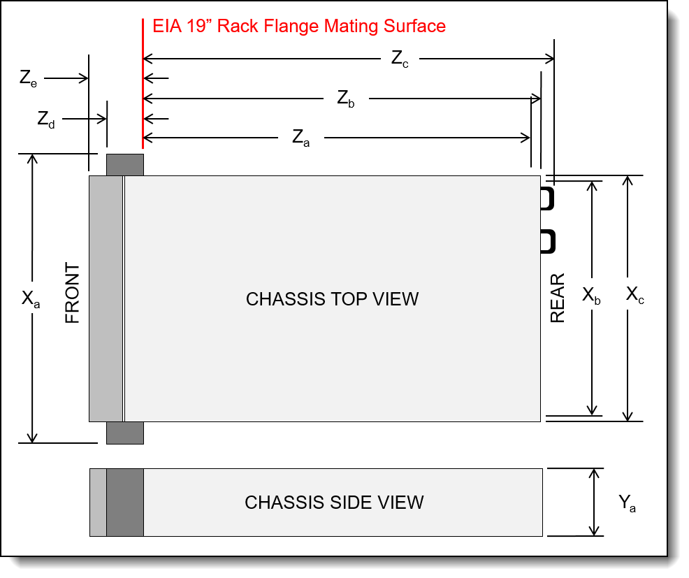
The shipping (cardboard packaging) dimensions of the SR650 V3 are as follows:
- Width: 592 mm (23.3 inches)
- Height: 282 mm (11.1 inches)
- Depth: 992 mm (39.1 inches)
The server has the following weight:
- Base configuration: 21.4 kg (47.2 lb)
- Maximum weight: 38.8 kg (85.5 lb)
Electrical specifications for AC input power supplies:
- Input voltage:
- 100 to 127 (nominal) Vac, 50 Hz or 60 Hz
- 200 to 240 (nominal) Vac, 50 Hz or 60 Hz
- 180 to 300 Vdc (China only)
- Inlet current: See the following table.
Electrical specifications for DC input power supply:
- Input voltage: -48 to -60 Vdc
- Inlet current (1100W power supply): 26 A
Operating environment
The SR650 V3 server complies with ASHRAE Class A2 specifications with most configurations, and depending on the hardware configuration, also complies with ASHRAE Class A3 and Class A4 specifications.
Depending on the hardware configuration, the SR650 V3 server also complies with ASHRAE Class H1 specification. System performance may be impacted when operating temperature is outside ASHRAE H1 specification.
Topics in this section:
Ambient temperature requirements
The restrictions to ASHRAE support are as follows (cooling by air):
- The ambient temperature must be limited to 35°C or lower if the server has any of the following components:
- Broadcom 57416 10GBASE-T 2-port OCP
- Broadcom 57454 10GBASE-T 4-port OCP
- PCIe network interface card (NIC) at a rate greater than or equal to 100 Gb
- Part with AOC and at the rate of 40 Gb
- The ambient temperature must be limited to 30°C or lower if the server has any of the following components:
- 24 x 2.5" or 12 x 3.5" front bay with middle bay or rear bay
- GPU adapters
- 256 GB 3DS RDIMM
- 350 W processor
- part with AOC and at a rate greater than 40 Gb
- 5600 MHz RDIMMs with capacity greater than or equal to 96 GB
- ThinkSystem 96GB TruDDR5 4800MHz (2Rx4) RDIMM
- ThinkSystem 128GB TruDDR5 4800MHz (4Rx4) 3DS RDIMM v1
- 4800 MHz 256 GB RDIMMs (except ThinkSystem 256GB TruDDR5 4800MHz (8Rx4) 3DS RDIMM v1)
- The ambient temperature must be limited to 25°C or lower if the server has any of the following components or configurations:
- 350 W processor installed in the chassis with 24 x 2.5" or 12 x 3.5" front drives
- 350 W processor installed in the 16 x 2.5" + FIO non-GPU configuration
- processor (270 W <=TDP <= 300 W) installed in the chassis with middle or rear drives
- GPU adapter installed in the chassis with 24 x 2.5" front drives
- GPU adapter and processor with TDP rating greater than 300 W installed in the chassis with 16 x 2.5" or 8 x 3.5" front drives
- drives larger than 3.84 TB installed in Gen 5 rear or middle NVMe drive bays
- 36 NVMe configuration
- 16 x 2.5" + FIO GPU configuration
- ThinkSystem 256GB TruDDR5 4800MHz (8Rx4) 3DS RDIMM v1
- ThinkSystem 96GB TruDDR5 4800MHz (2Rx4) RDIMM and ThinkSystem 128GB TruDDR5 5600MHz (2Rx4) RDIMM installed in the following configurations:
- 12 x 3.5" configurations including processors with TDP greater than to 350W
- 12 x 3.5" + middle/rear drive bay configurations including processors with TDP greater than 250W
- Intel Max 1100 GPU
- The following NVMe SSDs installed in the front 12 x 3.5" SAS/SATA + middle 8 x 2.5" NVMe or front 12 x 3.5" SAS/SATA + rear 4 x 2.5" NVMe configuration:
- ThinkSystem 2.5" U.2 P5336 61.44TB Read Intensive NVMe PCIe 4.0 x4 HS SSD
- ThinkSystem 2.5" U.2 P5336 30.72TB Read Intensive NVMe PCIe 4.0 x4 HS SSD
- ThinkSystem 2.5" U.2 P5336 15.36TB Read Intensive NVMe PCIe 4.0 x4 HS SSD
- H100 NVL GPU adapter
- BlueField-3 DPU adapters
The restrictions to ASHRAE support are as follows (cooling by Direct Water Cooling Module (DWCM)):
- The ambient temperature must be limited to 35°C or lower if the server has any of the following components or configurations:
- Broadcom 57416 10GBASE-T 2-port OCP
- Broadcom 57454 10GBASE-T 4-port OCP
- PCIe network interface card (NIC) at a rate greater than or equal to 100 Gb
- Part with AOC and at the rate of 40 Gb
- GPU adapters (< 300 W) installed in 8 x 3.5" or 16 x 2.5" configurations
- 64 GB < DIMM < 256 GB
- 8 x 2.5" GPU configuration
- storage configuration without middle or rear NVMe backplane
- The ambient temperature must be limited to 30°C or lower if the server has any of the following components:
- 256 GB 3DS RDIMM
- part with AOC and at a rate greater than 40 GB
- GPU adapters (>= 300 W) installed in 8 x 3.5" or 16 x 2.5" configurations
- three A40 GPU adapters installed in 24 x 2.5" configurations
- storage configuration with middle or rear NVMe backplane
- 5600 MHz RDIMMs with capacity greater than or equal to 96 GB
- ThinkSystem 96GB TruDDR5 4800MHz (2Rx4) RDIMM
- ThinkSystem 128GB TruDDR5 4800MHz (4Rx4) 3DS RDIMM v1
- 4800 MHz 256 GB RDIMMs (except ThinkSystem 256GB TruDDR5 4800MHz (8Rx4) 3DS RDIMM v1)
- H100 NVL GPU adapter
- The ambient temperature must be limited to 25°C or lower if the server has any of the following components:
- three H800/H100 GPU adapters installed in 24 x 2.5" configurations
- three H800/H100 GPU adapters installed in 16 x 2.5" + FIO configurations
- ThinkSystem 256GB TruDDR5 4800MHz (8Rx4) 3DS RDIMM v1
- The following NVMe SSDs installed in the front 12 x 3.5" SAS/SATA + middle 8 x 2.5" NVMe or front 12 x 3.5" SAS/SATA + rear 4 x 2.5" NVMe configuration:
- ThinkSystem 2.5" U.2 P5336 61.44TB Read Intensive NVMe PCIe 4.0 x4 HS SSD
- ThinkSystem 2.5" U.2 P5336 30.72TB Read Intensive NVMe PCIe 4.0 x4 HS SSD
- ThinkSystem 2.5" U.2 P5336 15.36TB Read Intensive NVMe PCIe 4.0 x4 HS SSD
- BlueField-3 DPU adapters
Server shutdown: When the ambient temperature is greater than the supported max temperature (ASHARE A4 45°C), the server will shut down. The server will not power on again until the ambient temperature falls within the supported temperature range.
For additional information, see the Environmental specifications and Thermal rules sections in the product documentation:
https://pubs.lenovo.com/sr650-v3/server_specifications_environmental
https://pubs.lenovo.com/sr650-v3/thermal_rules
Temperature and humidity
The server is supported in the following environment:
- Air temperature:
- Operating:
- ASHRAE Class A2: 10°C to 35°C (50°F to 95°F); the maximum ambient temperature decreases by 1°C for every 300 m (984 ft) increase in altitude above 900 m (2,953 ft).
- ASHRAE Class A3: 5°C to 40°C (41°F to 104°F); the maximum ambient temperature decreases by 1°C for every 175 m (574 ft) increase in altitude above 900 m (2,953 ft).
- ASHRAE Class A4: 5°C to 45°C (41°F to 113°F); the maximum ambient temperature decreases by 1°C for every 125 m (410 ft) increase in altitude above 900 m (2,953 ft).
- ASHRAE Class H1: 5 °C to 25 °C (41 °F to 77 °F); Decrease the maximum ambient temperature by 1°C for every 500 m (1640 ft) increase in altitude above 900 m (2,953 ft).
- Server off: 5°C to 45°C (41°F to 113°F)
- Shipment/storage: -40°C to 60°C (-40°F to 140°F)
- Operating:
- Maximum altitude: 3,050 m (10,000 ft)
- Relative Humidity (non-condensing):
- Operating
- ASHRAE Class A2: 8% to 80%; maximum dew point: 21°C (70°F)
- ASHRAE Class A3: 8% to 85%; maximum dew point: 24°C (75°F)
- ASHRAE Class A4: 8% to 90%; maximum dew point: 24°C (75°F)
- ASHRAE Class H1: 8% to 80%; Maximum dew point: 17°C (63°F)
- Shipment/storage: 8% to 90%
- Operating
Acoustical noise emissions
The server has the following acoustic noise emissions declaration:
Notes:
- These sound levels were measured in controlled acoustical environments according to procedures specified by ISO7779 and are reported in accordance with ISO 9296.
- The declared acoustic sound levels are based on the following configurations, which may change depending on configuration/conditions:
- Typical configuration: 8x 2.5-inch front drive bays, 6x standard fans, 2x 205 W CPUs, 8x 64 GB RDIMMs, 8x 2.4 TB SAS HDDs, 1x RAID 940-8i, 1x Intel X710-T2L 10GBASE-T 2-port OCP, 2x 750 W PSUs, No GPUs
- Storage configuration: 12x 3.5-inch front drive bays, 6x high performance fans, 2x 205 W CPUs, 16x 64 GB RDIMMs, 20x 14 TB SAS HDDs, 1x RAID 940-32i, 1x Intel X710-T2L 10GBASE-T 2-port OCP, 2x 1100 W PSUs, No GPUs
- GPU configuration: 16x 2.5-inch front drive bays, 6x high performance fans, 2x 205 W CPUs, 32x 64 GB RDIMMs, 16x 2.4 TB SAS HDDs, 1 x RAID 940-16i, 1x Intel X710-T2L 10GBASE-T 2-port OCP, 2x 1800 W PSUs, 3x A100 GPUs
- Government regulations (such as those prescribed by OSHA or European Community Directives) may govern noise level exposure in the workplace and may apply to you and your server installation. The actual sound pressure levels in your installation depend upon a variety of factors, including the number of racks in the installation; the size, materials, and configuration of the room; the noise levels from other equipment; the room ambient temperature, and employee's location in relation to the equipment. Further, compliance with such government regulations depends on a variety of additional factors, including the duration of employees' exposure and whether employees wear hearing protection. Lenovo recommends that you consult with qualified experts in this field to determine whether you are in compliance with the applicable regulations.
Shock and vibration
The server has the following vibration and shock limits:
- Vibration:
- Operating: 0.21 G rms at 5 Hz to 500 Hz for 15 minutes across 3 axes
- Non-operating: 1.04 G rms at 2 Hz to 200 Hz for 15 minutes across 6 surfaces
- Shock:
- Operating: 15 G for 3 milliseconds in each direction (positive and negative X, Y, and Z axes)
- Non-operating:
- 23 kg - 31 kg: 35 G for 152 in./sec velocity change across 6 surfaces (3x GPU config, 2.5” config)
- 32 kg - 68 kg: 35 G for 136 in./sec velocity change across 6 surfaces (20x 3.5” HDD config)
Particulate contamination
Airborne particulates (including metal flakes or particles) and reactive gases acting alone or in combination with other environmental factors such as humidity or temperature might damage the system that might cause the system to malfunction or stop working altogether.
The following specifications indicate the limits of particulates that the system can tolerate:
- Reactive gases:
- The copper reactivity level shall be less than 200 Angstroms per month (Å/month)
- The silver reactivity level shall be less than 200 Å/month
- Airborne particulates:
- The room air should be continuously filtered with MERV 8 filters.
- Air entering a data center should be filtered with MERV 11 or preferably MERV 13 filters.
- The deliquescent relative humidity of the particulate contamination should be more than 60% RH
- Environment must be free of zinc whiskers
For additional information, see the Specifications section of the documentation for the server, available from the Lenovo Documents site, https://pubs.lenovo.com/
Water infrastructure for the Lenovo Neptune Processor DWC Module
The Lenovo Processor Neptune Core Module is the liquid-based processor cooling offering for the SR650 V3, as described in the Lenovo Processor Neptune Core Module section.
The open-loop cooling module requires the following water infrastructure components in the rack cabinet and data center:
- Supported 42U or 48U rack cabinet
The 42U or 48U Heavy Duty Rack Cabinet (machine types 7D6D or 7D6E) are supported. Two 0U mounting points are required for the water manifolds, at the rear of the rack cabinet, one either side.
For information about the 42U and 48U Heavy Duty Rack Cabinets, see the product guide:
https://lenovopress.lenovo.com/lp1498-lenovo-heavy-duty-rack-cabinets - 38-port water manifold (machine type 7DE6), installed in the rear of the rack cabinet
The manifold provides quick-disconnect couplings that each server in the rack are connected to. Ordering information is in the table below. Note: With a rack full of SR650 V3 servers, only up to 19 of the manifold ports are used.
- Coolant distribution unit (CDU), either in-rack or in-row
In-rack CDUs are installed at the bottom of the rack cabinet. The supported in-rack CDU is as follows:
- Lenovo Neptune DWC RM100 In-Rack CDU; see the RM100 In-Rack Coolant Distribution Unit section
In-row CDUs are separate cabinets that are typically installed at the end of a row of rack cabinets. Examples of suitable in-row CDUs include (but not limited to):
- Vertiv XDU450 CDU
- Vertiv XDU600 CDU
- Vertiv XDU100 CDU
- Hose kit to connect to the CDU to the manifold
Ordering information is in the table below.
The following figure shows the major components of the solution.
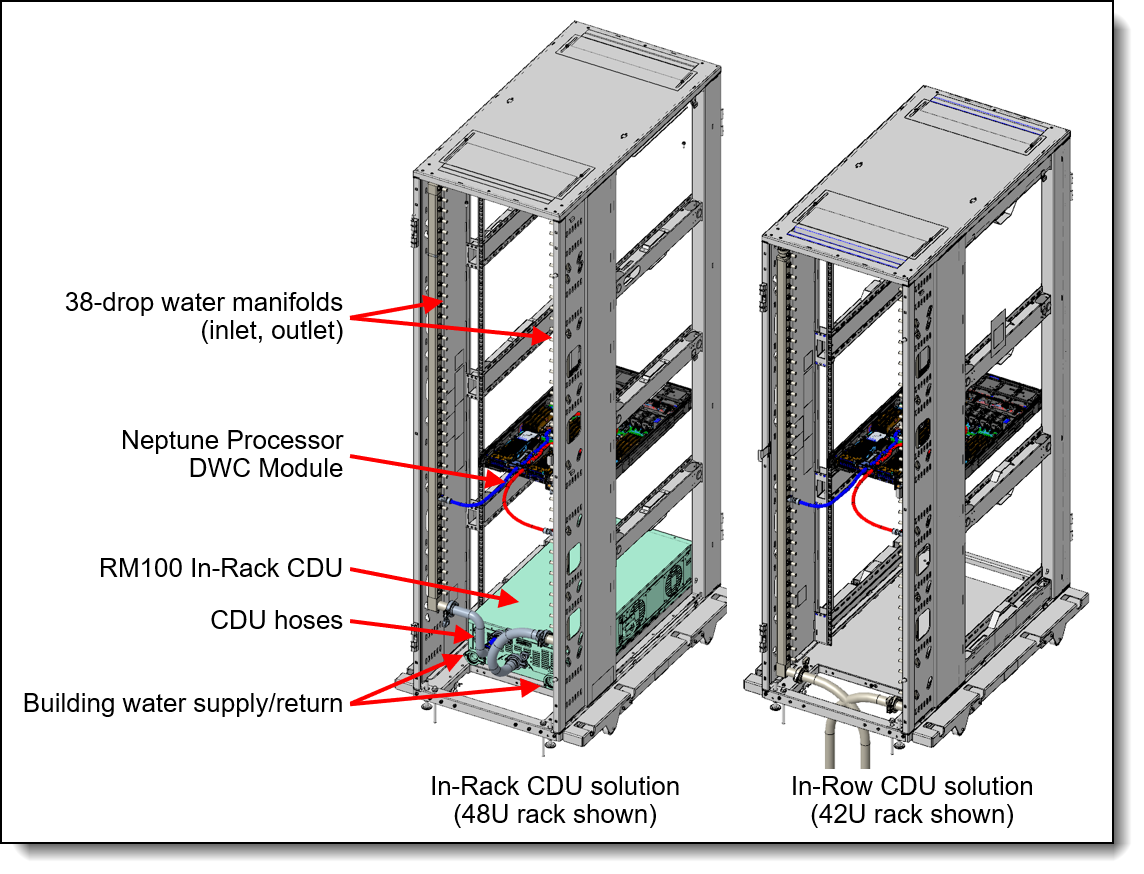
Figure 29. Water manifold connections
Configuration requirements:
- Maximum number of SR650 V3 servers supported in a rack:
- 48U rack: 19 servers
- 42U rack with in-rack CDU: 18 servers
- 42U rack without in-rack CDU: 19 servers
- Inlet water flow rate:
- 0.5 LPM: Maximum 40°C inlet water temperature
- 1.0 LPM: Maximum 45°C inlet water temperature
- 1.5 LPM: Maximum 50°C inlet water temperature
- Water pressure requirement:
- Maximum operating node inlet pressure = 43.5 psi (3 bars)
Note: Water quality must be maintained over the lifetime of the system to receive warranty and support on affecting components. For water quality requirement, see Lenovo Neptune Direct Water-Cooling Standards
The 38-drop water manifold and hoses can be ordered as listed in the following table.
Configuration notes:
- This water connection solution described here cannot be used with the DW612S and N1380 enclosures as the water requirements are different.
- The hoses for in-row CDUs that are listed in the table above have Eaton FD83 quick-disconnect couplings
Warranty upgrades and post-warranty support
The SR650 V3 has a 1-year or 3-year warranty based on the machine type of the system:
- 7D75 - 1 year warranty
- 7D76 - 3 year warranty
- 7D77 - 3 year warranty
Our global network of regional support centers offers consistent, local-language support enabling you to vary response times and level of service* to match the criticality of your support needs:
- Standard Next Business Day – Best choice for non-essential systems requiring simple maintenance.
- Premier Next Business Day – Best choice for essential systems requiring technical expertise from senior-level Lenovo engineers.
- Premier 24x7 4-Hour Response – Best choice for systems where maximum uptime is critical.
- Premier Enhanced Storage Support 24x7 4-Hour Response – Best choice for storage systems where maximum uptime is critical.
For more information, consult the brochure Lenovo Operational Support Services for Data Centers Services.
* Some service levels may not be available in all markets. Contact your sales representative for more information.
Services
Lenovo Data Center Services empower you at every stage of your IT lifecycle. From expert advisory and strategic planning to seamless deployment and ongoing support, we ensure your infrastructure is built for success. Our comprehensive services accelerate time to value, minimize downtime, and free your IT staff to focus on driving innovation and business growth.
Note: Some service options may not be available in all markets or regions. For more information, go to https://lenovolocator.com/. For information about Lenovo service upgrade offerings that are available in your region, contact your local Lenovo sales representative or business partner.
In this section:
- Lenovo Advisory Services
- Lenovo Plan & Design Services
- Lenovo Deployment, Migration, and Configuration Services
- Lenovo Support Services
- Lenovo Managed Services
- Lenovo Sustainability Services
Lenovo Advisory Services
Lenovo Advisory Services simplify the planning process, enabling customers to build future-proofed strategies in as little as six weeks. Consultants provide guidance on projects including VM migration, storage, backup and recovery, and cost management to accelerate time to value, improve cost efficiency, and build a flexibly scalable foundation.
- Assessment Services
An Assessment helps solve your IT challenges through an onsite, multi-day session with a Lenovo technology expert. We perform a tools-based assessment which provides a comprehensive and thorough review of a company's environment and technology systems. In addition to the technology based functional requirements, the consultant also discusses and records the non-functional business requirements, challenges, and constraints. Assessments help organizations like yours, no matter how large or small, get a better return on your IT investment and overcome challenges in the ever-changing technology landscape.
- Design Services
Professional Services consultants perform infrastructure design and implementation planning to support your strategy. The high-level architectures provided by the assessment service are turned into low level designs and wiring diagrams, which are reviewed and approved prior to implementation. The implementation plan will demonstrate an outcome-based proposal to provide business capabilities through infrastructure with a risk-mitigated project plan.
Lenovo Plan & Design Services
Unlock faster time to market with our tailored, strategic design workshops to align solution approaches with your business goals and technical requirements. Leverage our deep solution expertise and end-to-end delivery partnership to meet your goals efficiently and effectively.
Lenovo Deployment, Migration, and Configuration Services
Optimize your IT operations by shifting labor-intensive functions to Lenovo's skilled technicians for seamless on-site or remote deployment, configuration, and migration. Enjoy peace of mind, faster time to value, and comprehensive knowledge sharing with your IT staff, backed by our best-practice methodology.
- Deployment Services for Storage and ThinkAgile
A comprehensive range of remote and onsite options tailored specifically for your business needs to ensure your storage and ThinkAgile hardware are fully operational from the start.
- Hardware Installation Services
A full-range, comprehensive setup for your hardware, including unpacking, inspecting, and positioning components to ensure your equipment is operational and error-free for the most seamless and efficient installation experience, so you can quickly benefit from your investments.
- DM/DG File Migration Services
Take the burden of file migration from your IT’s shoulders. Our experts will align your requirements and business objectives to the migration plans while coordinating with your team to plan and safely execute the data migration to your storage platforms.
- DM/DG/DE Health Check Services
Our experts perform proactive checks of your Firmware and system health to ensure your machines are operating at peak and optimal efficiency to maximize up-time, avoid system failures, ensure the security of IT solutions and simplify maintenance.
- Factory Integrated Services
A suite of value-added offerings provided during the manufacturing phase of a server or storage system that reduces time to value. These services aim at improving your hardware deployment experience and enhance the quality of a standard configuration before it arrives at your facility.
Lenovo Support Services
In addition to response time options for hardware parts, repairs, and labor, Lenovo offers a wide array of additional support services to ensure your business is positioned for success and longevity. Our goal is to reduce your capital outlays, mitigate your IT risks, and accelerate your time to productivity.
- Premier Support for Data Centers
Your direct line to the solution that promises the best, most comprehensive level of support to help you fully unlock the potential of your data center.
- Premier Support Plus (PSP) for Servers 24x7 4-Hour Response
Helping customers reduce unplanned downtime by moving from reactive support to proactive and preventative care
- Premier Enhanced Storage Support (PESS)
Gain all the benefits of Premier Support for Data Centers, adding dedicated storage specialists and resources to elevate your storage support experience to the next level.
- Committed Service Repair (CSR)
Our commitment to ensuring the fastest, most seamless resolution times for mission-critical systems that require immediate attention to ensure minimal downtime and risk for your business. This service is only available for machines under the Premier 4-Hour Response SLA.
- Multivendor Support Services (MVS)
Your single point of accountability for resolution support across vast range of leading Server, Storage, and Networking OEMs, allowing you to manage all your supported infrastructure devices seamlessly from a single source.
- Keep Your Drive (KYD)
Protect sensitive data and maintain compliance with corporate retention and disposal policies to ensure your data is always under your control, regardless of the number of drives that are installed in your Lenovo server.
- Technical Account Manager (TAM)
Your single point of contact to expedite service requests, provide status updates, and furnish reports to track incidents over time, ensuring smooth operations and optimized performance as your business grows.
- Enterprise Software Support (ESS)
Gain comprehensive, single-source, and global support for a wide range of server operating systems and Microsoft server applications.
For more information, consult the brochure Lenovo Operational Support Services for Data Centers.
Lenovo Managed Services
Achieve peak efficiency, high security, and minimal disruption with Lenovo's always-on Managed Services. Our real-time monitoring, 24x7 incident response, and problem resolution ensure your infrastructure operates seamlessly. With quarterly health checks for ongoing optimization and innovation, Lenovo's remote active monitoring boosts end-user experience and productivity by keeping your data center's hardware performing at its best.
Lenovo Managed Services provides continuous 24x7 remote monitoring (plus 24x7 call center availability) and proactive management of your data center using state-of-the-art tools, systems, and practices by a team of highly skilled and experienced Lenovo services professionals.
Quarterly reviews check error logs, verify firmware & OS device driver levels, and software as needed. We’ll also maintain records of latest patches, critical updates, and firmware levels, to ensure you systems are providing business value through optimized performance.
Lenovo Sustainability Services
- Asset Recovery Services
Lenovo Asset Recovery Services (ARS) provides a secure, seamless solution for managing end-of-life IT assets, ensuring data is safely sanitized while contributing to a more circular IT lifecycle. By maximizing the reuse or responsible recycling of devices, ARS helps businesses meet sustainability goals while recovering potential value from their retired equipment. For more information, see the Asset Recovery Services offering page.
- CO2 Offset Services
Lenovo’s CO2 Offset Services offer a simple and transparent way for businesses to take tangible action on their IT footprint. By integrating CO2 offsets directly into device purchases, customers can easily support verified climate projects and track their contributions, making meaningful progress toward their sustainability goals without added complexity.
- Lenovo Certified Refurbished
Lenovo Certified Refurbished offers a cost-effective way to support IT circularity without compromising on quality and performance. Each device undergoes rigorous testing and certification, ensuring reliable performance and extending its lifecycle. With Lenovo’s trusted certification, you gain peace of mind while making a more sustainable IT choice.
Lenovo TruScale
Lenovo TruScale XaaS is your set of flexible IT services that makes everything easier. Streamline IT procurement, simplify infrastructure and device management, and pay only for what you use – so your business is free to grow and go anywhere.
Lenovo TruScale is the unified solution that gives you simplified access to:
- The industry’s broadest portfolio – from pocket to cloud – all delivered as a service
- A single-contract framework for full visibility and accountability
- The global scale to rapidly and securely build teams from anywhere
- Flexible fixed and metered pay-as-you-go models with minimal upfront cost
- The growth-driving combination of hardware, software, infrastructure, and solutions – all from one single provider with one point of accountability.
For information about Lenovo TruScale offerings that are available in your region, contact your local Lenovo sales representative or business partner.
Regulatory compliance
The SR650 V3 conforms to the following standards:
- ANSI/UL 62368-1
- IEC 62368-1 (CB Certificate and CB Test Report)
- CSA C22.2 No. 62368-1
- Mexico NOM-019
- India BIS 13252 (Part 1)
- Germany GS
- TUV-GS (EN62368-1, and EK1-ITB2000)
- Brazil INMETRO
- South Africa NRCS LOA
- Ukraine UkrCEPRO
- Morocco CMIM Certification (CM)
- Russia, Belorussia and Kazakhstan, TP EAC 037/2016 (for RoHS)
- Russia, Belorussia and Kazakhstan, EAC: TP TC 004/2011 (for Safety); TP TC 020/2011 (for EMC)
- CE, UKCA Mark (EN55032 Class A, EN62368-1, EN55024, EN55035, EN61000-3-2, EN61000-3-3, (EU) 2019/424, and EN IEC 63000 (RoHS))
- CE, UKCA Mark (EN55032 Class A, EN62368-1, EN55035, EN61000-3-11, EN61000-3-12, (EU) 2019/424, and EN IEC 63000 (RoHS))
- FCC - Verified to comply with Part 15 of the FCC Rules, Class A
- Canada ICES-003, issue 7, Class A
- CISPR 32, Class A, CISPR 35
- Korea KN32, Class A, KN35
- Japan VCCI, Class A
- Taiwan BSMI CNS15936, Class A; CNS15598-1; Section 5 of CNS15663
- Australia/New Zealand AS/NZS CISPR 32, Class A; AS/NZS 62368.1
- UL Green Guard, UL2819
- Energy Star 4.0
- EPEAT (NSF/ ANSI 426) Bronze
- Japanese Energy-Saving Act
- EU2019/424 Energy Related Product (ErP Lot9)
- China CCC certificate, GB17625.1; GB4943.1; GB/T9254
- China CECP certificate, CQC3135
- China CELP certificate, HJ 2507-2011
External drive enclosures
The server supports attachment to external drive enclosures using a RAID controller with external ports or a SAS host bus adapter. Adapters supported by the server are listed in the SAS adapters for external storage section.
Note: Information provided in this section is for ordering reference purposes only. For the operating system and adapter support details, refer to the interoperability matrix for a particular storage enclosure that can be found on the Lenovo Data Center Support web site:
http://datacentersupport.lenovo.com
For details about supported drives, adapters, and cables, see the following Lenovo Press Product Guides:
- Lenovo Storage D1212 and D1224
http://lenovopress.lenovo.com/lp0512 - Lenovo Storage D3284
http://lenovopress.lenovo.com/lp0513 - Lenovo ThinkSystem D4390
https://lenovopress.lenovo.com/lp1681
External storage systems
Lenovo offers the ThinkSystem DE Series, ThinkSystem DG Series, ThinkSystem DM Series and ThinkSystem DS Series external storage systems for high-performance storage. See the DE Series, DG Series and DM Series product guides for specific controller models, expansion enclosures and configuration options:
- ThinkSystem DE Series Storage
https://lenovopress.com/storage/thinksystem/de-series#rt=product-guide - ThinkSystem DS Series Storage
https://lenovopress.lenovo.com/storage/thinksystem/ds-series - ThinkSystem DM Series Storage
https://lenovopress.com/storage/thinksystem/dm-series#rt=product-guide - ThinkSystem DG Series Storage
https://lenovopress.com/storage/thinksystem/dg-series#rt=product-guide
External backup units
The following table lists the external backup options that are offered by Lenovo.
For more information, see the list of Product Guides in the Backup units category:
https://lenovopress.com/servers/options/backup
Fibre Channel SAN switches
Lenovo offers the ThinkSystem DB Series of Fibre Channel SAN switches for high-performance storage expansion. See the DB Series product guides for models and configuration options:
- ThinkSystem DB Series SAN Switches:
https://lenovopress.com/storage/switches#rt=product-guide
Uninterruptible power supply units
The following table lists the uninterruptible power supply (UPS) units that are offered by Lenovo.
† Only available in China and the Asia Pacific market.
For more information, see the list of Product Guides in the UPS category:
https://lenovopress.com/servers/options/ups
Power distribution units
The following table lists the power distribution units (PDUs) that are offered by Lenovo.
| Part number |
Feature code |
Description |
ANZ
|
ASEAN
|
Brazil
|
EET
|
MEA
|
RUCIS
|
WE
|
HTK
|
INDIA
|
JAPAN
|
LA
|
NA
|
PRC
|
|---|---|---|---|---|---|---|---|---|---|---|---|---|---|---|---|
| 0U Basic PDUs | |||||||||||||||
| 4PU7A93176 | C0QH | 0U 36 C13 and 6 C19 Basic 32A 1 Phase PDU v2 | Y | Y | Y | Y | Y | Y | Y | Y | Y | N | Y | Y | Y |
| 4PU7A93169 | C0DA | 0U 36 C13 and 6 C19 Basic 32A 1 Phase PDU | Y | Y | Y | Y | Y | Y | Y | Y | Y | N | Y | Y | Y |
| 4PU7A93177 | C0QJ | 0U 24 C13/C15 and 24 C13/C15/C19 Basic 32A 3 Phase WYE PDU v2 | Y | Y | Y | Y | Y | Y | Y | Y | Y | Y | Y | Y | Y |
| 4PU7A93170 | CBVF | 0U 24 C13/C15 and 24 C13/C15/C19 Basic 32A 3 Phase WYE PDU | Y | Y | Y | Y | Y | Y | Y | Y | Y | Y | Y | Y | Y |
| 00YJ776 | ATZY | 0U 36 C13/6 C19 24A 1 Phase PDU | N | Y | Y | N | N | N | N | N | N | Y | Y | Y | N |
| 00YJ779 | ATZX | 0U 21 C13/12 C19 48A 3 Phase PDU | N | N | Y | N | N | N | Y | N | N | Y | Y | Y | N |
| 00YJ777 | ATZZ | 0U 36 C13/6 C19 32A 1 Phase PDU | Y | Y | Y | Y | Y | Y | Y | Y | Y | N | N | Y | Y |
| 00YJ778 | AU00 | 0U 21 C13/12 C19 32A 3 Phase PDU | Y | Y | N | Y | Y | Y | Y | Y | Y | N | N | Y | Y |
| 0U Switched and Monitored PDUs | |||||||||||||||
| 4PU7B08148 | CD15 | 0U 3 C13 and 18 C19 Monitored 48A 3 Phase WYE PDU | N | N | N | N | N | N | N | N | N | N | N | Y | N |
| 4PU7B08149 | CD16 | 0U 3 C13 and 18 C19 Monitored 63A 3 Phase WYE PDU | N | N | N | Y | N | N | Y | N | N | N | N | N | N |
| 4PU7A93181 | C0QN | 0U 21 C13/C15 and 21 C13/C15/C19 Switched and Monitored 48A 3 Phase Delta PDU v2 (60A derated) | N | Y | N | N | N | N | N | Y | N | Y | N | Y | N |
| 4PU7A93174 | CBVJ | 0U 21 C13/C15 and 21 C13/C15/C19 Switched and Monitored 60A 3 Phase Delta PDU | Y | Y | Y | Y | Y | Y | Y | Y | Y | Y | Y | Y | Y |
| 4PU7A93178 | C0QK | 0U 20 C13 and 4 C19 Switched and Monitored 32A 1 Phase PDU v2 | Y | Y | Y | Y | Y | Y | Y | Y | Y | N | Y | Y | Y |
| 4PU7A93171 | C0D8 | 0U 20 C13 and 4 C19 Switched and Monitored 32A 1 Phase PDU | Y | Y | Y | Y | Y | Y | Y | Y | Y | N | Y | Y | Y |
| 4PU7A93182 | C0QP | 0U 18 C13/C15 and 18 C13/C15/C19 Switched and Monitored 63A 3 Phase WYE PDU v2 | Y | Y | Y | Y | Y | Y | Y | Y | Y | Y | Y | Y | Y |
| 4PU7A93175 | C0CS | 0U 18 C13/C15 and 18 C13/C15/C19 Switched and Monitored 63A 3 Phase WYE PDU | Y | Y | Y | Y | Y | Y | Y | Y | Y | N | Y | Y | Y |
| 4PU7A93180 | C0QM | 0U 18 C13/C15 and 18 C13/C15/C19 Switched and Monitored 32A 3 Phase WYE PDU v2 | Y | Y | Y | Y | Y | Y | Y | Y | Y | Y | Y | Y | Y |
| 4PU7A93173 | CBVH | 0U 18 C13/C15 and 18 C13/C15/C19 Switched and Monitored 32A 3 Phase WYE PDU | Y | Y | Y | Y | Y | Y | Y | Y | Y | Y | Y | Y | Y |
| 4PU7A93179 | C0QL | 0U 16 C13/C15 and 16 C13/C15/C19 Switched and Monitored 24A 1 Phase PDU v2 (30A derated) | N | Y | N | N | N | N | N | Y | N | Y | Y | Y | N |
| 4PU7A93172 | CBVG | 0U 16 C13/C15 and 16 C13/C15/C19 Switched and Monitored 30A 1 Phase PDU | Y | Y | Y | Y | Y | Y | Y | Y | Y | Y | Y | Y | Y |
| 00YJ783 | AU04 | 0U 12 C13/12 C19 Switched and Monitored 48A 3 Phase PDU | N | N | Y | N | N | N | Y | N | N | Y | Y | Y | N |
| 00YJ781 | AU03 | 0U 20 C13/4 C19 Switched and Monitored 24A 1 Phase PDU | N | N | Y | N | Y | N | Y | N | N | Y | Y | Y | N |
| 00YJ782 | AU02 | 0U 18 C13/6 C19 Switched and Monitored 32A 3 Phase PDU | Y | Y | Y | Y | Y | Y | Y | Y | Y | N | Y | N | Y |
| 00YJ780 | AU01 | 0U 20 C13/4 C19 Switched and Monitored 32A 1 Phase PDU | Y | Y | Y | Y | Y | Y | Y | Y | Y | N | Y | N | Y |
| 1U Basic PDUs | |||||||||||||||
| 4PU7B12339 | CE6L | 1U Basic 16A 1 Phase PDU | Y | Y | Y | Y | Y | Y | Y | Y | Y | N | Y | Y | Y |
| 1U Switched and Monitored PDUs | |||||||||||||||
| 4PU7A90808 | C0D4 | 1U 18 C19/C13 Switched and monitored 48A 3P WYE PDU V2 ETL | N | N | N | N | N | N | N | Y | N | Y | Y | Y | N |
| 4PU7A81117 | BNDV | 1U 18 C19/C13 switched and monitored 48A 3P WYE PDU - ETL | N | N | N | N | N | N | N | N | N | N | N | Y | N |
| 4PU7A90809 | C0DE | 1U 18 C19/C13 Switched and monitored 48A 3P WYE PDU V2 CE | Y | Y | Y | Y | Y | Y | Y | Y | Y | Y | Y | N | Y |
| 4PU7A81118 | BNDW | 1U 18 C19/C13 switched and monitored 48A 3P WYE PDU – CE | Y | Y | Y | Y | Y | Y | Y | Y | Y | Y | Y | N | Y |
| 4PU7A90810 | C0DD | 1U 18 C19/C13 Switched and monitored 80A 3P Delta PDU V2 | N | N | N | N | N | N | N | Y | N | Y | Y | Y | N |
| 4PU7A77467 | BLC4 | 1U 18 C19/C13 Switched and Monitored 80A 3P Delta PDU | N | N | N | N | N | N | N | N | N | Y | N | Y | N |
| 4PU7A90811 | C0DC | 1U 12 C19/C13 Switched and monitored 32A 3P WYE PDU V2 | Y | Y | Y | Y | Y | Y | Y | Y | Y | Y | Y | Y | Y |
| 4PU7A77468 | BLC5 | 1U 12 C19/C13 switched and monitored 32A 3P WYE PDU | Y | Y | Y | Y | Y | Y | Y | Y | Y | Y | Y | Y | Y |
| 4PU7A90812 | C0DB | 1U 12 C19/C13 Switched and monitored 60A 3P Delta PDU V2 | N | N | N | N | N | N | N | Y | N | Y | Y | Y | N |
| 4PU7A77469 | BLC6 | 1U 12 C19/C13 switched and monitored 60A 3P Delta PDU | N | N | N | N | N | N | N | N | N | N | N | Y | N |
| 46M4002 | 5896 | 1U 9 C19/3 C13 Switched and Monitored DPI PDU | Y | Y | Y | Y | Y | Y | Y | Y | Y | Y | Y | Y | Y |
| 46M4004 | 5894 | 1U 12 C13 Switched and Monitored DPI PDU | Y | Y | Y | Y | Y | Y | Y | Y | Y | Y | Y | Y | Y |
| 46M4003 | 5897 | 1U 9 C19/3 C13 Switched and Monitored 60A 3 Phase PDU | Y | Y | Y | Y | Y | Y | Y | Y | Y | Y | Y | Y | Y |
| 46M4005 | 5895 | 1U 12 C13 Switched and Monitored 60A 3 Phase PDU | Y | Y | Y | Y | Y | Y | Y | Y | Y | Y | Y | Y | Y |
| 1U C13 Enterprise PDUs (12x IEC 320 C13 outlets) | |||||||||||||||
| 39M2816 | 6030 | DPI C13 PDU+ | Y | Y | Y | Y | Y | Y | Y | Y | Y | Y | Y | Y | Y |
| 39Y8941 | 6010 | Enterprise C13 PDU | Y | Y | Y | Y | Y | Y | Y | Y | Y | Y | Y | Y | Y |
| 1U C19 Enterprise PDUs (6x IEC 320 C19 outlets) | |||||||||||||||
| 39Y8948 | 6060 | Enterprise C19 PDU | Y | Y | Y | Y | Y | Y | Y | Y | Y | Y | Y | Y | Y |
| 39Y8923 | 6061 | Enterprise C19 3 phase PDU (60a) | N | N | Y | N | N | N | Y | N | N | N | Y | Y | N |
| 1U Front-end PDUs (3x IEC 320 C19 outlets) | |||||||||||||||
| 39Y8938 | 6002 | DPI 30amp/125V Front-end PDU with NEMA L5-30P | Y | Y | Y | Y | Y | Y | Y | Y | Y | Y | Y | Y | Y |
| 39Y8939 | 6003 | DPI 30amp/250V Front-end PDU with NEMA L6-30P | Y | Y | Y | Y | Y | Y | Y | Y | Y | Y | Y | Y | Y |
| 39Y8934 | 6005 | DPI 32amp/250V Front-end PDU with IEC 309 2P+Gnd | Y | Y | Y | Y | Y | Y | Y | Y | Y | Y | Y | Y | Y |
| 39Y8940 | 6004 | DPI 60amp/250V Front-end PDU with IEC 309 2P+Gnd connector | Y | N | Y | Y | Y | Y | Y | N | N | Y | Y | Y | N |
| 39Y8935 | 6006 | DPI 63amp/250V Front-end PDU with IEC 309 2P+Gnd connector | Y | Y | Y | Y | Y | Y | Y | Y | Y | Y | Y | Y | Y |
| 1U NEMA PDUs (6x NEMA 5-15R outlets) | |||||||||||||||
| 39Y8905 | 5900 | DPI 100-127v PDU with Fixed Nema L5-15P line cord | Y | Y | Y | Y | Y | Y | Y | Y | Y | Y | Y | Y | Y |
| Line cords for 1U PDUs that ship without a line cord | |||||||||||||||
| 40K9611 | 6504 | 4.3m, 32A/380-415V, EPDU/IEC 309 3P+N+G 3ph wye (non-US) Line Cord | Y | Y | Y | Y | Y | Y | Y | Y | Y | Y | Y | Y | Y |
| 40K9612 | 6502 | 4.3m, 32A/230V, EPDU to IEC 309 P+N+G (non-US) Line Cord | Y | Y | Y | Y | Y | Y | Y | Y | Y | Y | Y | Y | Y |
| 40K9613 | 6503 | 4.3m, 63A/230V, EPDU to IEC 309 P+N+G (non-US) Line Cord | Y | Y | Y | Y | Y | Y | Y | Y | Y | Y | Y | Y | Y |
| 40K9614 | 6500 | 4.3m, 30A/208V, EPDU to NEMA L6-30P (US) Line Cord | Y | Y | Y | Y | Y | Y | Y | Y | Y | Y | Y | Y | Y |
| 40K9615 | 6501 | 4.3m, 60A/208V, EPDU to IEC 309 2P+G (US) Line Cord | N | N | Y | N | N | N | Y | N | N | Y | Y | Y | N |
| 40K9617 | 6505 | 4.3m, 32A/230V, Souriau UTG to AS/NZS 3112 (Aus/NZ) Line Cord | Y | Y | Y | Y | Y | Y | Y | Y | Y | Y | Y | Y | Y |
| 40K9618 | 6506 | 4.3m, 32A/250V, Souriau UTG Female to KSC 8305 (S. Korea) Line Cord | Y | Y | Y | Y | Y | Y | Y | Y | Y | Y | Y | Y | Y |
For more information, see the Lenovo Press documents in the PDU category:
https://lenovopress.com/servers/options/pdu
| Supported markets | Unsupported markets |
|---|---|
|
|
| Supported markets | Unsupported markets |
|---|---|
|
(None) |
| Supported markets | Unsupported markets |
|---|---|
|
|
| Supported markets | Unsupported markets |
|---|---|
|
(None) |
| Supported markets | Unsupported markets |
|---|---|
|
(None) |
| Supported markets | Unsupported markets |
|---|---|
|
(None) |
| Supported markets | Unsupported markets |
|---|---|
|
(None) |
| Supported markets | Unsupported markets |
|---|---|
|
(None) |
| Supported markets | Unsupported markets |
|---|---|
| (None) |
|
| Supported markets | Unsupported markets |
|---|---|
| (None) |
|
| Supported markets | Unsupported markets |
|---|---|
| (None) |
|
| Supported markets | Unsupported markets |
|---|---|
|
|
| Supported markets | Unsupported markets |
|---|---|
|
|
| Supported markets | Unsupported markets |
|---|---|
|
|
| Supported markets | Unsupported markets |
|---|---|
|
|
| Supported markets | Unsupported markets |
|---|---|
|
|
| Supported markets | Unsupported markets |
|---|---|
| (None) |
|
| Supported markets | Unsupported markets |
|---|---|
| (None) |
|
| Supported markets | Unsupported markets |
|---|---|
| (None) |
|
| Supported markets | Unsupported markets |
|---|---|
|
|
| Supported markets | Unsupported markets |
|---|---|
| (None) |
|
| Supported markets | Unsupported markets |
|---|---|
| (None) |
|
| Supported markets | Unsupported markets |
|---|---|
|
(None) |
| Supported markets | Unsupported markets |
|---|---|
|
(None) |
| Supported markets | Unsupported markets |
|---|---|
|
(None) |
| Supported markets | Unsupported markets |
|---|---|
|
(None) |
| Supported markets | Unsupported markets |
|---|---|
|
|
| Supported markets | Unsupported markets |
|---|---|
|
(None) |
| Supported markets | Unsupported markets |
|---|---|
|
(None) |
| Supported markets | Unsupported markets |
|---|---|
|
(None) |
| Supported markets | Unsupported markets |
|---|---|
|
|
| Supported markets | Unsupported markets |
|---|---|
|
(None) |
| Supported markets | Unsupported markets |
|---|---|
|
(None) |
| Supported markets | Unsupported markets |
|---|---|
|
(None) |
| Supported markets | Unsupported markets |
|---|---|
|
(None) |
| Supported markets | Unsupported markets |
|---|---|
|
(None) |
| Supported markets | Unsupported markets |
|---|---|
| (None) |
|
| Supported markets | Unsupported markets |
|---|---|
| (None) |
|
| Supported markets | Unsupported markets |
|---|---|
|
(None) |
| Supported markets | Unsupported markets |
|---|---|
|
(None) |
| Supported markets | Unsupported markets |
|---|---|
| (None) |
|
| Supported markets | Unsupported markets |
|---|---|
|
|
| Supported markets | Unsupported markets |
|---|---|
|
|
| Supported markets | Unsupported markets |
|---|---|
|
|
| Supported markets | Unsupported markets |
|---|---|
|
|
| Supported markets | Unsupported markets |
|---|---|
|
|
| Supported markets | Unsupported markets |
|---|---|
|
|
| Supported markets | Unsupported markets |
|---|---|
|
|
| Supported markets | Unsupported markets |
|---|---|
|
|
| Supported markets | Unsupported markets |
|---|---|
|
|
| Supported markets | Unsupported markets |
|---|---|
| (None) |
|
| Supported markets | Unsupported markets |
|---|---|
| (None) |
|
| Supported markets | Unsupported markets |
|---|---|
| (None) |
|
| Supported markets | Unsupported markets |
|---|---|
| (None) |
|
| Supported markets | Unsupported markets |
|---|---|
|
|
| Supported markets | Unsupported markets |
|---|---|
|
|
| Supported markets | Unsupported markets |
|---|---|
|
|
| Supported markets | Unsupported markets |
|---|---|
|
|
| Supported markets | Unsupported markets |
|---|---|
| (None) |
|
| Supported markets | Unsupported markets |
|---|---|
| (None) |
|
| Supported markets | Unsupported markets |
|---|---|
| (None) |
|
| Supported markets | Unsupported markets |
|---|---|
| (None) |
|
| Supported markets | Unsupported markets |
|---|---|
|
|
| Supported markets | Unsupported markets |
|---|---|
|
|
| Supported markets | Unsupported markets |
|---|---|
|
|
| Supported markets | Unsupported markets |
|---|---|
|
|
| Supported markets | Unsupported markets |
|---|---|
| (None) |
|
| Supported markets | Unsupported markets |
|---|---|
| (None) |
|
| Supported markets | Unsupported markets |
|---|---|
| (None) |
|
| Supported markets | Unsupported markets |
|---|---|
| (None) |
|
| Supported markets | Unsupported markets |
|---|---|
|
|
| Supported markets | Unsupported markets |
|---|---|
|
|
| Supported markets | Unsupported markets |
|---|---|
|
|
| Supported markets | Unsupported markets |
|---|---|
|
|
| Supported markets | Unsupported markets |
|---|---|
|
|
| Supported markets | Unsupported markets |
|---|---|
|
|
| Supported markets | Unsupported markets |
|---|---|
|
|
| Supported markets | Unsupported markets |
|---|---|
|
|
| Supported markets | Unsupported markets |
|---|---|
|
|
| Supported markets | Unsupported markets |
|---|---|
|
|
| Supported markets | Unsupported markets |
|---|---|
|
|
| Supported markets | Unsupported markets |
|---|---|
|
|
| Supported markets | Unsupported markets |
|---|---|
|
|
| Supported markets | Unsupported markets |
|---|---|
|
|
| Supported markets | Unsupported markets |
|---|---|
|
|
| Supported markets | Unsupported markets |
|---|---|
|
|
| Supported markets | Unsupported markets |
|---|---|
|
|
| Supported markets | Unsupported markets |
|---|---|
|
|
| Supported markets | Unsupported markets |
|---|---|
|
|
| Supported markets | Unsupported markets |
|---|---|
|
|
| Supported markets | Unsupported markets |
|---|---|
|
|
| Supported markets | Unsupported markets |
|---|---|
| (None) |
|
| Supported markets | Unsupported markets |
|---|---|
|
|
| Supported markets | Unsupported markets |
|---|---|
|
|
| Supported markets | Unsupported markets |
|---|---|
|
|
| Supported markets | Unsupported markets |
|---|---|
|
|
| Supported markets | Unsupported markets |
|---|---|
|
|
Rack cabinets
The following table lists the supported rack cabinets.
For specifications about these racks, see the Lenovo Rack Cabinet Reference, available from:
https://lenovopress.com/lp1287-lenovo-rack-cabinet-reference
For more information, see the list of Product Guides in the Rack cabinets category:
https://lenovopress.com/servers/options/racks
KVM console options
The following table lists the supported KVM consoles.
The following table lists the keyboards supported with the 1U 18.5" Standard Console (now withdrawn).
Note: These keyboards are not supported with the ThinkSystem 18.5" LCD Console.
The following table lists the available KVM switches and the options that are supported with them.
For more information, see the list of Product Guides in the KVM Switches and Consoles category:
http://lenovopress.com/servers/options/kvm
Lenovo Financial Services
Why wait to obtain the technology you need now? No payments for 90 days and predictable, low monthly payments make it easy to budget for your Lenovo solution.
- Flexible
Our in-depth knowledge of the products, services and various market segments allows us to offer greater flexibility in structures, documentation and end of lease options.
- 100% Solution Financing
Financing your entire solution including hardware, software, and services, ensures more predictability in your project planning with fixed, manageable payments and low monthly payments.
- Device as a Service (DaaS)
Leverage latest technology to advance your business. Customized solutions aligned to your needs. Flexibility to add equipment to support growth. Protect your technology with Lenovo's Premier Support service.
- 24/7 Asset management
Manage your financed solutions with electronic access to your lease documents, payment histories, invoices and asset information.
- Fair Market Value (FMV) and $1 Purchase Option Leases
Maximize your purchasing power with our lowest cost option. An FMV lease offers lower monthly payments than loans or lease-to-own financing. Think of an FMV lease as a rental. You have the flexibility at the end of the lease term to return the equipment, continue leasing it, or purchase it for the fair market value. In a $1 Out Purchase Option lease, you own the equipment. It is a good option when you are confident you will use the equipment for an extended period beyond the finance term. Both lease types have merits depending on your needs. We can help you determine which option will best meet your technological and budgetary goals.
Ask your Lenovo Financial Services representative about this promotion and how to submit a credit application. For the majority of credit applicants, we have enough information to deliver an instant decision and send a notification within minutes.
Seller training courses
The following sales training courses are offered for employees and partners (login required). Courses are listed in date order.
-
Partner Technical Webinar: Intel Xeon 6 & Ethernet NIC update
2026-07-14 | 60 minutes | Employees and Partners
DetailsPartner Technical Webinar: Intel Xeon 6 & Ethernet NIC update
In this 60 minute replay, Madhu Bramharouthu and Raj Pathak from Intel presented the latest information on Xeon 6 processors and Intel Ethernet adapters.
Published: 2026-07-14
Length: 60 minutes
Course code: JUL1026Start the training:
Employee link: Grow@Lenovo
Partner link: Lenovo 360 Learning Center
-
Lenovo Data Center Technical Certification Exam Study Guide
2026-07-13 | 10 minutes | Employees and Partners
DetailsLenovo Data Center Technical Certification Exam Study Guide
This guide includes information to help candidates prepare and register for the Data Center Technical practice and certification exams.
Published: 2026-07-13
Length: 10 minutes
Course code: LENU-322C-SGStart the training:
Employee link: Grow@Lenovo
Partner link: Lenovo 360 Learning Center
-
Lenovo Data Center Sales Certification Exam Study Guide
2026-07-13 | 10 minutes | Employees and Partners
DetailsLenovo Data Center Sales Certification Exam Study Guide
This guide includes information to help candidates prepare and register for the Data Center Sales practice and certification exams.
Published: 2026-07-13
Length: 10 minutes
Course code: LENU-122C-SGStart the training:
Employee link: Grow@Lenovo
Partner link: Lenovo 360 Learning Center
-
Partner Technical Webinar - TCE, DCSC, Enterprise Solutions, & LBPe ISG Financing
2026-06-09 | 60 minutes | Employees and Partners
DetailsPartner Technical Webinar - TCE, DCSC, Enterprise Solutions, & LBPe ISG Financing
In this 60‑minute replay, we received updates from George Scarbrough on TCE, Amit Chandok on the DCSC, Tracie Heath Garcia on LBPe ISG Financing, and Alejandro Perez Quintero on Enterprise IT Solutions.
Published: 2026-06-09
Length: 60 minutes
Course code: JUN0526Start the training:
Employee link: Grow@Lenovo
Partner link: Lenovo 360 Learning Center
-
Partner Technical Webinar - mAInstream Volume Enterprise AI
2026-05-11 | 45 minutes | Employees and Partners
DetailsPartner Technical Webinar - mAInstream Volume Enterprise AI
In this 45 minute replay, Alex “Doc” Docherty, Lenovo AI Technology for NA Channel, discussed Mainstream and volume Servers for enterprise AI solutions. He talked about the need, the supply and some new programs for the channel.
Published: 2026-05-11
Length: 45 minutes
Course code: MAY0826Start the training:
Employee link: Grow@Lenovo
Partner link: Lenovo 360 Learning Center
-
Partner Technical Webinar - AI Servers
2026-04-20 | 30 minutes | Employees and Partners
DetailsPartner Technical Webinar - AI Servers
In this 30 minute replay, Mark Bica, Lenovo NA ISG Server Product Manager, presented the Lenovo AI Servers. Mark also gave an update on M.2 changes the latest with TCE (Top Choice Express).
Published: 2026-04-20
Length: 30 minutes
Course code: APR1726Start the training:
Employee link: Grow@Lenovo
Partner link: Lenovo 360 Learning Center
-
Partner Technical Webinar - Server Review Racks, Towers & Edge
2026-03-16 | 60 minutes | Employees and Partners
DetailsPartner Technical Webinar - Server Review Racks, Towers & Edge
In this 60-minute replay, the Channel Solution Architect team provides an overview of the Lenovo ISG server portfolio. Eugene Grandberry, Ian Sloan, and Chris Laffey cover Towers, Racks, Edge, and TCE.
Published: 2026-03-16
Length: 60 minutes
Course code: MAR1326Start the training:
Employee link: Grow@Lenovo
Partner link: Lenovo 360 Learning Center
-
ISG Smarter Tools, Faster Deals and Better Outcomes
2026-02-27 | 40 minutes | Employees and Partners
DetailsISG Smarter Tools, Faster Deals and Better Outcomes
In this 40-minute video, we review several tools and programs from Lenovo ISG to help our Partners’ Data Center selling efforts: Smarter Tools / Faster Deals / Better Outcomes. We cover Top Choice Express, our premier program for supply optimized solutions. We next demonstrated DCSC, the Data Center Solution Configurator, Compete Tool for comparisons with our competition, and XClarity One, the next evolution of our XClarity Systems Management tool.
Published: 2026-02-27
Tags: DataCenter Products
Length: 40 minutes
Course code: FEB2426Start the training:
Employee link: Grow@Lenovo
Partner link: Lenovo 360 Learning Center
-
ThinkSystem Rackmount and Tower Servers powered by AMD
2026-02-23 | 25 minutes | Employees and Partners
DetailsThinkSystem Rackmount and Tower Servers powered by AMD
This course presents the key products and features of the ThinkSystem Rackmount and Tower server family powered by AMD processors. It describes customer benefits and will help you recognize when a specific product should be selected.
Published: 2026-02-23
By the end of this course, you should be able to:
- Identify products and features within the family
- Describe customer benefits offered by this family
- Recognize when a specific product should be selected
Last updated: 2/24/2026
Tags: Server, ThinkSystem
Length: 25 minutes
Course code: SXXW1216r11Start the training:
Employee link: Grow@Lenovo
Partner link: Lenovo 360 Learning Center
-
OneIQ Overview and Demo
2026-02-10 | 35 minutes | Employees and Partners
DetailsOneIQ Overview and Demo
In this 35-minute video, Peter Grant, Head of Customer Experience for OneIQ, presents and overview and demo of OneIQ for Lenovo Partners.
Published: 2026-02-10
Tags: Sales Tools
Length: 35 minutes
Course code: ONEIQ101Start the training:
Employee link: Grow@Lenovo
Partner link: Lenovo 360 Learning Center
-
Family Portfolio: ThinkSystem Rack and Tower Servers Powered by Intel
2026-02-04 | 25 minutes | Employees and Partners
DetailsFamily Portfolio: ThinkSystem Rack and Tower Servers Powered by Intel
This course is designed to give Lenovo sales and partner representatives a foundation of the ThinkSystem Intel Rackmount and Tower server family.
Published: 2026-02-04
After completing this course, you will be able to:
- Identify products within this ThinkSystem server family
- Describe features of this family
- Recognize when a specific product should be selected
Tags: Server, ThinkSystem
Length: 25 minutes
Course code: SXXW1204r15Start the training:
Employee link: Grow@Lenovo
Partner link: Lenovo 360 Learning Center
-
ThinkSystem Rack & Tower Server Primer - Module 2
2025-12-17 | 45 minutes | Employees Only
DetailsThinkSystem Rack & Tower Server Primer - Module 2
This course builds on the foundational concepts from the prework modules, helping Client Managers deepen their understanding of ThinkSystem Rack and Tower Servers and apply that knowledge to confidently initiate value-driven customer conversations. Please Note: The videos in this course are taken from the Module 2 live session led by Tikiri Wandregala.
Published: 2025-12-17
By the end of this course, you will be able to:
- Demonstrate the ability to initiate a data center discussion with a customer.
- Analyze and evaluate potential data center opportunities.
- Apply criteria to effectively qualify an opportunity.
- Locate and differentiate key resources and contacts.
Tags: DataCenter Products, ThinkSystem
Length: 45 minutes
Course code: DSRTB101Start the training:
Employee link: Grow@Lenovo
-
Partner Technical Webinar - Mainstream CPUs
2025-09-29 | 40 minutes | Employees and Partners
DetailsPartner Technical Webinar - Mainstream CPUs
In this 40-minute replay, Brad Violand, Lenovo ISG Category team, reviewed the strategy to optimize the CPU portfolio and ensuing changes to DCSC planned for October 1, 2025.
Published: 2025-09-29
Tags: Server
Length: 40 minutes
Course code: SEP2625Start the training:
Employee link: Grow@Lenovo
Partner link: Lenovo 360 Learning Center
-
Partner Technical Webinar - ISG Portfolio - Wayne's World
2025-09-25 | 60 minutes | Employees and Partners
DetailsPartner Technical Webinar - ISG Portfolio - Wayne's World
In this 60-minute replay, Wayne Pecht, Lenovo Channel SA, shared his extensive experience and unique approach to the ISG Portfolio "Wayne's World for Lenovo ISG"!
Published: 2025-09-25
Tags: Channel, Technical Sales
Length: 60 minutes
Course code: SEP1925Start the training:
Employee link: Grow@Lenovo
Partner link: Lenovo 360 Learning Center
-
FY26Q2 Easy SMB Quick Hit
2025-09-22 | 8 minutes | Employees and Partners
DetailsFY26Q2 Easy SMB Quick Hit
This Quick Hit introduces Lenovo Easy SMB, smarter business made simple. It allows businesses to move quickly, deploy modern AI-ready IT infrastructure with ease, and scale confidently, inside data centers or at the edge.
Published: 2025-09-22
Tags: Artificial Intelligence (AI), Infrastructure as a Service (IaaS), Microsoft, ThinkEdge, ThinkSystem, XClarity
Length: 8 minutes
Course code: SXXW2548aStart the training:
Employee link: Grow@Lenovo
Partner link: Lenovo 360 Learning Center
-
Think AI Weekly: ISG & SSG Better Together: Uniting AI Solutions & Services for Smarter Outcomes
2025-08-01 | 55 minutes | Employees Only
DetailsThink AI Weekly: ISG & SSG Better Together: Uniting AI Solutions & Services for Smarter Outcomes
View this session to hear from our speakers Allen Holmes, AI Technologist, ISG and Balaji Subramaniam, AI Regional Leader-Americas, SSG.
Published: 2025-08-01
Topics include:
• An overview of ISG & SSG AI CoE Offerings with Customer Case Studies
• The Enterprise AI Deal Engagement Flow with ISG and SSG
• How sellers can leverage this partnership to differentiate with Enterprise clients.
• NEW COURSE: From Inception to Execution: Evolution of an AI Deal
Tags: Artificial Intelligence (AI), Sales, Services, Technology Solutions, TruScale Infrastructure as a Service
Length: 55 minutes
Course code: DTAIW145Start the training:
Employee link: Grow@Lenovo
-
VTT-HPC: Explaining HPC Benchmarking: Processes, Standards and Best Practices
2025-07-30 | 87 minutes | Employees Only
DetailsVTT-HPC: Explaining HPC Benchmarking: Processes, Standards and Best Practices
Please join us as Eric Michel, HPC & AI Performance Team Coordinator and Kevin Dean, Sr Manager, HPC Performance, Projection & Operations speak with us about HPC Benchmarking.
Published: 2025-07-30
Topics will include:
• Why sellers need to request benchmarks
• How to request benchmarks
• How the team performs a benchmark
• The performance database
• Demonstration of the tool
Tags: Advanced Data Center, High Performance Computing (HPC), Technical Sales
Length: 87 minutes
Course code: DVHPC224Start the training:
Employee link: Grow@Lenovo
-
Family Portfolio: Server Component Options
2025-07-21 | 20 minutes | Employees and Partners
DetailsFamily Portfolio: Server Component Options
This course covers opportunities that are available to upsell server components. By upselling the correct components, you can increase the size and revenue of the original sale.
Published: 2025-07-21
After completing this course, you should be able to:
• Identify the opportunities for an upsell
• Recognize when specific products should be discussed
• Emphasize how a product benefits the customer
• Identify keywords that indicate upsell opportunities
Tags: Server, Storage
Length: 20 minutes
Course code: SXXW1109r2Start the training:
Employee link: Grow@Lenovo
Partner link: Lenovo 360 Learning Center
-
ThinkSystem Rack and Tower Introduction for ISO Client Managers
2025-06-16 | 20 minutes | Employees Only
DetailsThinkSystem Rack and Tower Introduction for ISO Client Managers
In this course, you will learn about Lenovo’s Data Center Portfolio, its ThinkSystem Family and the key features of the Rack and Tower servers. It will equip you with foundational knowledge which you can then expand upon by participating in the facilitated session of the curriculum.
Published: 2025-06-16
Tags: Server, ThinkSystem
Length: 20 minutes
Course code: DSRTO101r2_JPStart the training:
Employee link: Grow@Lenovo
-
Lenovo Data Center Product Portfolio
2025-06-11 | 20 minutes | Employees and Partners
DetailsLenovo Data Center Product Portfolio
This course introduces the Lenovo data center portfolio, and covers servers, storage, storage networking, and software-defined infrastructure products. After completing this course about Lenovo data center products, you will be able to identify product types within each data center family, describe Lenovo innovations that this product family or category uses, and recognize when a specific product should be selected.
Published: 2025-06-11
Course objectives:
1.Identify product types within each data center family
2.Describe the features of the product family or category
3.Recognize when a specific product should be selected
Tags: Advanced DataCenter, DataCenter Products, Server, ThinkAgile, ThinkEdge, ThinkSystem
Length: 20 minutes
Course code: SXXW1110r8Start the training:
Employee link: Grow@Lenovo
Partner link: Lenovo 360 Learning Center
-
VTT HPC: AI and the Impact on the Environment
2025-06-11 | 58 minutes | Employees Only
DetailsVTT HPC: AI and the Impact on the Environment
Please join us as Matthew Ziegler, Director of Lenovo Neptune and Sustainability speaks with us about AI and the Impact on the Environment.
Published: 2025-06-11
Topics will include:
- Why is ESG essential for your customer?
- How to find and read an eco declaration
- What is a product carbon footprint?
- Demo of the Lenovo Capacity Planner
Tags: Advanced DataCenter, Artificial Intelligence (AI), Environmental Social Governance (ESG), High-Performance Computing (HPC), Server
Length: 58 minutes
Course code: DVHPC223Start the training:
Employee link: Grow@Lenovo
-
Lenovo Cloud Architecture VTT: Supercharge Your Enterprise AI with NVIDIA AI Enterprise on Lenovo Hybrid AI Platform
2025-04-17 | 75 minutes | Employees and Partners
DetailsLenovo Cloud Architecture VTT: Supercharge Your Enterprise AI with NVIDIA AI Enterprise on Lenovo Hybrid AI Platform
Join us for an in-depth webinar with Justin King, Principal Product Marketing Manager for Enterprise AI exploring the power of NVIDIA AI Enterprise, delivering Generative and Agentic AI outcomes deployed with Lenovo Hybrid AI platform environments.
Published: 2025-04-17
In today’s data-driven landscape, AI is evolving at high speed, with new techniques delivering more accurate responses. Enterprises are seeking not just an understanding but also how they can achieve AI-driven business outcomes.
With this, the demand for secure, scalable, and high-performing AI operations-and the skills to deliver them-is top of mind for many. Learn how NVIDIA AI Enterprise, a comprehensive software suite optimized for NVIDIA GPUs, provides the tools and frameworks, including NVIDIA NIM, NeMo, and Blueprints, to accelerate AI development and deployment while reducing risk-all within the control and security of your Lenovo customer’s hybrid AI environment.
Tags: Artificial Intelligence (AI), Cloud, Data Management, Nvidia, Technical Sales
Length: 75 minutes
Course code: DVCLD221Start the training:
Employee link: Grow@Lenovo
Partner link: Lenovo 360 Learning Center
-
Family Portfolio: Storage Controller Options
2025-03-03 | 25 minutes | Employees and Partners
DetailsFamily Portfolio: Storage Controller Options
This course covers the storage controller options available for use in Lenovo servers. The classes of storage controller are discussed, along with a discussion of where they are used, and which to choose.
Published: 2025-03-03
After completing this course, you will be able to:
• Describe the classes of storage controllers
• Discuss where each controller class is used
• Describe the available options in each controller class
Tags: Sales, Storage
Length: 25 minutes
Course code: SXXW1111r2Start the training:
Employee link: Grow@Lenovo
Partner link: Lenovo 360 Learning Center
-
ThinkSystem Rack and Tower Introduction for ISO Client Managers
2024-12-10 | 20 minutes | Employees Only
DetailsThinkSystem Rack and Tower Introduction for ISO Client Managers
In this course, you will learn about Lenovo’s Data Center Portfolio, its ThinkSystem Family and the key features of the Rack and Tower servers. It will equip you with foundational knowledge which you can then expand upon by participating in the facilitated session of the curriculum.
Published: 2024-12-10
Course Objectives:
• By the end of this course, you should be able to:
• Identify Lenovo’s main data center brands.
• Describe the key components of the ThinkSystem Family servers.
• Differentiate between the Rack and Tower servers of the ThinkSystem Family.
• Understand the value Rack and Tower servers can provide to customers.
Tags: Server, ThinkSystem
Length: 20 minutes
Course code: DSRTO101r2Start the training:
Employee link: Grow@Lenovo
-
SAP Webinar for Lenovo Sellers: Lenovo Portfolio Update for SAP Landscapes
2024-06-04 | 60 minutes | Employees Only
DetailsSAP Webinar for Lenovo Sellers: Lenovo Portfolio Update for SAP Landscapes
Join Mark Kelly, Advisory IT Architect with the Lenovo Global SAP Center of Competence as he discusses:
Published: 2024-06-04
•Challenges in the SAP environment
•Lenovo On-premise Solutions for SAP
•Lenovo support resources for SAP solutions
Tags: SAP, ThinkAgile, ThinkEdge, ThinkSystem
Length: 60 minutes
Course code: DSAPF101Start the training:
Employee link: Grow@Lenovo
-
Introduction to DDR5 Memory
2022-08-23 | 10 minutes | Employees and Partners
DetailsIntroduction to DDR5 Memory
This course introduces DDR5 memory, describes new features of this memory generation, and discusses the advantages to customers of this new memory generation.
Published: 2022-08-23
Tags: Server, Technology solutions
Length: 10 minutes
Course code: SXXW2502Start the training:
Employee link: Grow@Lenovo
Partner link: Lenovo 360 Learning Center
1-10 of 26 courses.
Related publications and links
For more information, see these resources:
- ThinkSystem SR650 V3 product page:
https://www.lenovo.com/us/en/p/racks/len21ts0013 - ThinkSystem SR650 V3 datasheet
https://lenovopress.com/ds0143 - Interactive 3D Tour of the ThinkSystem SR650 V3:
https://lenovopress.lenovo.com/lp1621-thinksystem-sr650-v3-interactive-3d-tour - ThinkSystem SR650 V3 drivers and support
http://datacentersupport.lenovo.com/products/servers/thinksystem/sr650v3/7d76/downloads - Lenovo Hardware Installation & Removal Videos on the SR650 V3:
https://www.youtube.com/playlist?list=PLYV5R7hVcs-BmyijyY0-lNvapM4fTV5Gf - Lenovo ThinkSystem SR650 V3 product publications:
https://pubs.lenovo.com/sr650-v3/- User Guide, which includes:
- System Configuration Guide
- Hardware Maintenance Guide
- Rack Installation Guides
- Messages and Codes Reference
- UEFI Manual for ThinkSystem Servers
- User Guide, which includes:
- User Guides for options:
https://serveroption.lenovo.com - ServerProven hardware compatibility:
http://serverproven.lenovo.com
Trademarks
Lenovo and the Lenovo logo are trademarks or registered trademarks of Lenovo in the United States, other countries, or both. A current list of Lenovo trademarks is available on the Web at https://www.lenovo.com/us/en/legal/copytrade/.
The following terms are trademarks of Lenovo in the United States, other countries, or both:
Lenovo®
AnyBay®
Neptune®
ServerProven®
System x®
ThinkAgile®
ThinkEdge®
ThinkShield®
ThinkSystem®
XClarity®
The following terms are trademarks of other companies:
AMD, AMD Instinct™, and Solarflare™ are trademarks of Advanced Micro Devices, Inc.
Intel®, the Intel logo, Intel Core®, Intel Optane®, and Xeon® are trademarks of Intel Corporation or its subsidiaries.
Linux® is the trademark of Linus Torvalds in the U.S. and other countries.
Microsoft, ActiveX, Hyper-V, PowerPoint, PowerShell, SharePoint, Windows, and Windows Server are trademarks of Microsoft Corporation in the United States, other countries, or both.
TPC® is a trademark of Transaction Processing Performance Council.
SPEC®, SPEC ACCEL®, SPEC CPU®, SPEC MPI®, SPEC OMP®, SPEChpc™, SPECjbb®, SPECpower®, SPECrate®, and SPECspeed® are trademarks of the Standard Performance Evaluation Corporation (SPEC).
IBM® and IBM Security® are trademarks of IBM in the United States, other countries, or both.
NVIDIA®, NVIDIA DOCA®, NVIDIA Quadro®, NVIDIA RTX®, Quadro RTX®, and Quadro® are trademarks of NVIDIA Corporation.
Other company, product, or service names may be trademarks or service marks of others.
Configure and Buy
Please select a locale
Please select your market:
Full Change History
Changes in the July 15, 2026 update:
- Added the Performance benchmarks section
Changes in the May 19, 2026 update:
- Added the following preconfigured model for customers in Brazil - Preconfigured models section
- 7D76A0B9BR
Changes in the May 5, 2026 update:
- Added the following preconfigured model for customers in Brazil - Preconfigured models section
- 7D76A0B8BR
Changes in the April 2, 2026 update:
- Added information about the following feature code for CTO orders - Encryption Enablement section
- Drive Encryption Enablement (not supported with vSAN), CES1
Changes in the March 7, 2026 update:
- Added Top Choice Stock indicator for all preconfigured models - Preconfigured models section
Changes in the February 12, 2026 update:
- Added a new Top Choice section introducing Top Choice Express and Top Choice Stock
- Added a Top Choice Express column to all component tables in the product guide
Changes in the February 3, 2026 update:
- Added the following 2.5-inch drives - Internal drive options section:
- ThinkSystem 2.5" U.2 SN861 1.92TB Read Intensive NVMe PCIe 5.0 x4 HS SSD, 4XB7B10396
- ThinkSystem 2.5" U.2 SN861 3.84TB Read Intensive NVMe PCIe 5.0 x4 HS SSD, 4XB7B10397
- ThinkSystem 2.5" U.2 SN861 7.68TB Read Intensive NVMe PCIe 5.0 x4 HS SSD, 4XB7B10398
- ThinkSystem 2.5" U.2 SN861 15.36TB Read Intensive NVMe PCIe 5.0 x4 HS SSD, 4XB7B10399
- Added the following 3.5-inch drives - Internal drive options section:
- ThinkSystem 3.5" U.2 VA 1.92TB Read Intensive NVMe PCIe 5.0 x4 HS SSD, 4XB7B13984
- ThinkSystem 3.5" U.2 VA 3.84TB Read Intensive NVMe PCIe 5.0 x4 HS SSD, 4XB7B13985
- ThinkSystem 3.5" U.2 VA 7.68TB Read Intensive NVMe PCIe 5.0 x4 HS SSD, 4XB7B13986
- ThinkSystem 3.5" U.2 VA 15.36TB Read Intensive NVMe PCIe 5.0 x4 HS SSD, 4XB7B13987
- Added the following network adapter - Network adapters section
- ThinkSystem NVIDIA BlueField-3 B3220 VPI QSFP112 2P 200G PCIe Gen5 x16 with Tin Plating Connector, 4XC7B08942
Changes in the January 28, 2026 update:
- Added a note regarding the use of Vendor Agnostic (VA) drives with VMware vSAN configurations - Internal drive options section
Changes in the January 23, 2026 update:
- The following backplanes with integrated SAS expanders are not supported with cluster applications - Front drive bays section
- ThinkSystem 2U 12x3.5" SAS/SATA with Rear 4-Bay Expander Backplane (BQ2S)
- ThinkSystem 2U 24x2.5" SAS/SATA with Rear 4-Bay Expander Backplane (BQ2T)
Changes in the December 19, 2025 update:
- In the DCSC configurator, 7500 PRO and 7500 MAX U.3 drives can only be selected when a Tri-Mode controller is also selected - Internal drive options section
Changes in the December 16, 2025 update:
- New preconfigured models for customers in the Australia & New Zealand - Preconfigured models section:
- 7D76A0B3AU, 7D76A0B0AU
Changes in the December 10, 2025 update:
- The following RAID feature codes for CTO orders are withdrawn - M.2 drives and 7mm drives sections
- ThinkSystem Raid 5350-8i for 7MM SATA boot Enablement, BVL2
- ThinkSystem RAID 5350-8i for M.2 SATA Boot Enablement, BVL1
- ThinkSystem RAID 5350-8i Internal Adapter for 7MM SATA boot Enablement, BW1V
- ThinkSystem RAID 5350-8i Internal Adapter for M.2 SATA boot Enablement, BW1U
- The following 7mm field upgrades are withdrawn - 7mm drives section
- ThinkSystem SR650 V3 7mm SATA/NVMe 2-Bay Non-Raid Enablement Kit, 4XH7A87068
- ThinkSystem SR650 V3 7mm SATA/NVMe SFF RAID Enablement Kit, 4XH7A88465
- ThinkSystem SR650 V3 7mm NVMe 2-Bay RAID Enablement Kit, 4XH7A88463
Changes in the December 3, 2025 update:
- Corrected the RAID controller in the following models - Preconfigured models section:
- Australia/New Zealand: 7D76A062AU
- India: 7D76A078SG, 7D76A07BSG
Changes in the December 2, 2025 update:
- New preconfigured models for customers in the AP region - Preconfigured models section:
- 7D76A0B4AP, 7D76A0B1AP
- New preconfigured model for customers in Korea - Preconfigured models section:
- 7D76A0AYCN
Changes in the November 25, 2025 update:
- Added the following 2.5-inch NVMe drives - Internal drive options section
- ThinkSystem 2.5" U.2 VA 960GB Read Intensive NVMe PCIe 4.0 x4 HS SSD, 4XB7B11683
- ThinkSystem 2.5" U.2 VA 800GB Mixed Use NVMe PCIe 4.0 x4 HS SSD, 4XB7B11682
- Added the following 3.5-inch SATA drives - Internal drive options section
- ThinkSystem 3.5" VA 480GB Read Intensive SATA 6Gb HS SSD SED, 4XB7B11648
- ThinkSystem 3.5" VA 960GB Read Intensive SATA 6Gb HS SSD SED, 4XB7B11649
- ThinkSystem 3.5" VA 1.92TB Read Intensive SATA 6Gb HS SSD SED, 4XB7B11650
- ThinkSystem 3.5" VA 3.84TB Read Intensive SATA 6Gb HS SSD SED, 4XB7B11651
- ThinkSystem 3.5" VA 480GB Mixed Use SATA 6Gb HS SSD SED, 4XB7B11652
- ThinkSystem 3.5" VA 960GB Mixed Use SATA 6Gb HS SSD SED, 4XB7B11653
- ThinkSystem 3.5" VA 1.92TB Mixed Use SATA 6Gb HS SSD SED, 4XB7B11654
- ThinkSystem 3.5" VA 3.84TB Mixed Use SATA 6Gb HS SSD SED, 4XB7B11655
Changes in the November 4, 2025 update:
- Added the following VPI adapter - Network adapters section:
- ThinkSystem NVIDIA ConnectX-7 NDR400 OSFP 1-port PCIe Gen5 VPI Adapter, 4XC7A95508
- Added the following -48V DC power supply - Power supplies section:
- ThinkSystem 1100W -48V DC Hot-Swap Gen2 Power Supply v2, 4P57A89415
Changes in the October 22, 2025 update:
- Corrected 3.5-inch drive config 6A - Field upgrades section
Changes in the October 13, 2025 update:
- Added configs 105-108 to the tables of internal storage field upgrades - Field upgrades section
Changes in the October 10, 2025 update:
- Refreshed the tables of preconfigured models - Preconfigured models section
Changes in the September 23, 2025 update:
- New preconfigured models for customers in the AP region - Preconfigured models section:
- 7D76A0A0AP, 7D76A0A6AP, 7D76A09YAP, 7D76A09VAP, 7D76A09WAP, 7D76A09XAP, 7D76A09SAP, 7D76101DAP, 7D76101BAP, 7D76101EAP, 7D76101CAP, 7D76A0A5AP, 7D76101FAP, 7D76A0A2AP
- New preconfigured models for customers in Brazil - Preconfigured models section:
- 7D761014BR, 7D761012BR, 7D761018BR, 7D761016BR, 7D76101ABR
- New preconfigured models for customers in India - Preconfigured models section:
- 7D76A0A7SG, 7D76A0A9SG, 7D76A09TSG, 7D76A0A8SG, 7D76A09ZSG, 7D76A0A1SG, 7D76A0AASG, 7D76A0A4SG, 7D76A09USG, 7D76A0A3SG, 7D76A0ABSG
- New preconfigured models for customers in Korea - Preconfigured models section:
- 7D76A09RCN
- New preconfigured models for customers in the EMEA region - Preconfigured models section:
- 7D76100WEA, 7D761010EA, 7D76100XEA, 7D76100ZEA, 7D76100YEA
- New preconfigured models for customers in the Latin Ameria region - Preconfigured models section:
- 7D761017LA, 7D761015LA, 7D761019LA, 7D761013LA, 7D761011LA
Changes in the September 16, 2025 update:
- Added the following drive - Internal drive options section:
- ThinkSystem 2.5" U.2 VA 30.72TB Read Intensive NVMe PCIe 5.0 x4 HS SSD, 4XB7A93126
Changes in the September 9, 2025 update:
- New preconfigured models for customers in the HTK region - Models section:
- 7D76A09NCN, 7D76A09MCN, 7D76A09QCN, 7D76A09PCN
- New preconfigured model for customers in Brazil - Models section:
- 7D76A09LBR
Changes in the September 2, 2025 update:
- Storage configurations with the 9450-32i have been withdrawn - Storage configurations section
Changes in the August 29, 2025 update:
- Updated the drive tables to include the reactivated 7500 PRO and 7500 MAX NVMe SSDs - Internal drive options section
Changes in the August 26, 2025 update
- Added the following 2.5-inch NVMe drives - Internal drive options section
- ThinkSystem 2.5" U.2 6550 30.72TB Read Intensive NVMe PCIe 5.0 x4 HS SSD, 4XB7B08330
- ThinkSystem 2.5" U.2 6550 61.44TB Read Intensive NVMe PCIe 5.0 x4 HS SSD, 4XB7B08331
- ThinkSystem 2.5" U.2 BM1743 122.88TB Read Intensive NVMe PCIe 5.0 x4 HS SSD, 4XB7B09031
- The server now supports 4,423.68TB using 36x 122.88TB 2.5-inch NVMe SSDs - Standard specifications section
- Added the following 3.5-inch HDDs - Internal drive options section
- ThinkSystem 3.5" 14TB 7.2K SAS 12Gb Hot Swap 512e HDD v2, 4XB7B04313
- ThinkSystem 3.5" 18TB 7.2K SAS 12Gb Hot Swap 512e HDD v2, 4XB7B04314
- ThinkSystem 3.5" 22TB 7.2K SAS 12Gb Hot Swap 512e HDD v2, 4XB7B00011
- ThinkSystem 3.5" 14TB 7.2K SATA 6Gb Hot Swap 512e HDD v2, 4XB7B04544
- ThinkSystem 3.5" 18TB 7.2K SATA 6Gb Hot Swap 512e HDD v2, 4XB7B04545
- ThinkSystem 3.5" 22TB 7.2K SATA 6Gb Hot Swap 512e HDD v2, 4XB7B00012
- Added the following M.2 drives - Internal drive options section
- ThinkSystem M.2 VA 480GB Read Intensive NVMe PCIe 4.0 x4 NHS SSD, 4XB7B09650
- ThinkSystem M.2 VA 960GB Read Intensive NVMe PCIe 4.0 x4 NHS SSD, 4XB7B09651
Changes in the August 7, 2025 update:
- Updated the drive tables - Internal drive options section:
- Most branded NVMe SSDs are no longer offered for CTO orders
- Use vendor-agnostic (VA) drives instead
Changes in the July 31, 2025 update:
- The following memory DIMMs have been withdrawn - Memory options section:
- ThinkSystem 256GB TruDDR5 4800MHz (8Rx4) 3DS RDIMM v1, BZPM
- ThinkSystem 256GB TruDDR5 4800MHz (8Rx4) 3DS RDIMM v2, 4X77A77035
Changes in the July 29, 2025 update:
- Added the following model for customers in the Latin America region - Models section:
- 7D76100GLA
Changes in the July 18, 2025 update:
- Clarified the number of cooling fans required for 1-processor configurations - Cooling section
Changes in the July 6, 2025 update:
- Correction: With Riser 3 selected, up to 12x NVMe drives can be connected (two 8-bay backplanes) using Onboard NVMe - NVMe drive support section and I/O expansion section
Changes in the July 1, 2025 update:
- New model for customers in India - Preconfigured models section:
- 7D76A09GSG
- New models for customers in Brazil - Preconfigured models section:
- 7D76100MBR, 7D76100PBR, 7D76100LBR, 7D76100NBR
- New models for customers in Latin America markets - Preconfigured models section:
- 7D76100QLA, 7D76100ULA, 7D76100TLA, 7D76100HLA, 7D76100RLA
- Added the following drives - Internal drive options section:
- ThinkSystem 2.5" VA 1.92TB Mixed Use SATA 6Gb HS SSD SED, 4XB7B09974
- ThinkSystem 2.5" VA 3.84TB Mixed Use SATA 6Gb HS SSD SED, 4XB7B09975
- ThinkSystem 2.5" VA 480GB Mixed Use SATA 6Gb HS SSD SED, 4XB7B09972
- ThinkSystem 2.5" VA 960GB Mixed Use SATA 6Gb HS SSD SED, 4XB7B09973
- ThinkSystem 2.5" VA 480GB Read Intensive SATA 6Gb HS SSD SED, 4XB7B09967
- ThinkSystem 2.5" VA 960GB Read Intensive SATA 6Gb HS SSD SED, 4XB7B09968
- ThinkSystem 2.5" VA 1.92TB Read Intensive SATA 6Gb HS SSD SED, 4XB7B09969
- ThinkSystem 2.5" VA 3.84TB Read Intensive SATA 6Gb HS SSD SED, 4XB7B09970
- ThinkSystem 2.5" VA 7.68TB Read Intensive SATA 6Gb HS SSD SED, 4XB7B09971
Changes in the June 24, 2025 update:
- The RAID 9450 adapters now support Tri-Mode (SAS, SATA, and NVMe x1) - Tri-mode support section
- Added the following RAID adapters for SAS/SATA/NVMe x1 (Tri-Mode) - Controllers for internal storage section:
- ThinkSystem RAID 9450-8i 4GB Flash PCIe Gen4 24Gb Adapter for U.3, CBMY
- ThinkSystem RAID 9450-16i 8GB Flash PCIe Gen4 24Gb Adapter for U.3, CBMZ
- ThinkSystem RAID 9450-32i 8GB Flash PCIe Gen4 24Gb Adapter (x1 SAS/SATA/NVMe U.3 only), CBN0
- Updated the storage adapter table to separate NVMe x1 connectivity (Tri-Mode) and NVMe x4 connectivity - Controllers for internal storage section
- Added the following storage configs - Internal storage section
- Config 11-4 - 24x SAS/SATA using 9450-32i adapter
- Config 11-5 - 24x SAS/SATA/NVMe Tri-Mode using 9450-32i adapter
- Config 11-6 - 16x SAS/SATA/NVMe Tri-Mode using 9450-16i adapter
- Config 11-7 - 8x SAS/SATA/NVMe Tri-Mode using 9450-8i adapter
Changes in the June 23, 2025 update:
- Reversing the update from June 20. The following OCP adapter is supported either in the front or rear OCP slot (whichever is configured) - Network adapters section:
- ThinkSystem Broadcom 57412 10GBase-T 4-Port OCP Ethernet Adapter, 4XC7A95696
Changes in the June 20, 2025 update:
- The following OCP adapter is not supported when the OCP slot is located at the front of the server - Network adapters section:
- ThinkSystem Broadcom 57412 10GBase-T 4-Port OCP Ethernet Adapter, 4XC7A95696
Changes in the June 16, 2025 update:
- Clarified that the 9450-32i is only supported in the SR650 V3 with NVMe drives - Controllers for internal storage section
Changes in the June 3, 2025 update:
- New preconfigured model for customers in India - Models section:
- 7D76A09DSG
Changes in the May 27, 2025 update:
- Storage configs 6A-3 and 6A-4 require 2 processors; no support for 1 processor - Internal storage section
- Added support for the following Ethernet adapters - Network adapters section:
- ThinkSystem Broadcom 57412 10GBase-T 4-Port OCP Ethernet Adapter, 4XC7A95696
- ThinkSystem Broadcom 57412 10GBase-T 4-Port PCIe Ethernet Adapter, 4XC7A95697
Changes in the May 20, 2025 update:
- Added the following M.2 drives - Internal drive options section:
- ThinkSystem M.2 VA 240GB Read Intensive SATA 6Gb NHS SSD, 4XB7B07587
- ThinkSystem M.2 VA 480GB Read Intensive SATA 6Gb NHS SSD, 4XB7B07588
- ThinkSystem M.2 VA 960GB Read Intensive SATA 6Gb NHS SSD, 4XB7B07589
- Added the following NVMe drive - Internal drive options section:
- ThinkSystem 2.5" PM9D3a 30.72TB Read Intensive NVMe PCIe 5.0 x4 HS SSD, 4XB7B04552
- Added the following 2.5-inch SAS drives - Internal drive options section:
- ThinkSystem 2.5" VA 960GB Read Intensive SAS 24Gb HS SSD, 4XB7B07600
- ThinkSystem 2.5" VA 1.92TB Read Intensive SAS 24Gb HS SSD, 4XB7B07601
- ThinkSystem 2.5" VA 3.84TB Read Intensive SAS 24Gb HS SSD, 4XB7B07602
- ThinkSystem 2.5" VA 7.68TB Read Intensive SAS 24Gb HS SSD, 4XB7B07603
- ThinkSystem 2.5" VA 15.36TB Read Intensive SAS 24Gb HS SSD, 4XB7B07604
- ThinkSystem 2.5" VA 30.72TB Read Intensive SAS 24Gb HS SSD, 4XB7B07605
- ThinkSystem 2.5" VA 800GB Mixed Use SAS 24Gb HS SSD, 4XB7B07612
- ThinkSystem 2.5" VA 1.6TB Mixed Use SAS 24Gb HS SSD, 4XB7B07613
- ThinkSystem 2.5" VA 3.2TB Mixed Use SAS 24Gb HS SSD, 4XB7B07614
- ThinkSystem 2.5" VA 6.4TB Mixed Use SAS 24Gb HS SSD, 4XB7B07615
- Added the following 3.5-inch SAS drives - Internal drive options section:
- ThinkSystem 3.5" VA 960GB Read Intensive SAS 24Gb HS SSD, 4XB7B07606
- ThinkSystem 3.5" VA 1.92TB Read Intensive SAS 24Gb HS SSD, 4XB7B07607
- ThinkSystem 3.5" VA 3.84TB Read Intensive SAS 24Gb HS SSD, 4XB7B07608
- ThinkSystem 3.5" VA 7.68TB Read Intensive SAS 24Gb HS SSD, 4XB7B07609
- ThinkSystem 3.5" VA 15.36TB Read Intensive SAS 24Gb HS SSD, 4XB7B07610
- ThinkSystem 3.5" VA 800GB Mixed Use SAS 24Gb HS SSD, 4XB7B07616
- ThinkSystem 3.5" VA 1.6TB Mixed Use SAS 24Gb HS SSD, 4XB7B07617
- ThinkSystem 3.5" VA 3.2TB Mixed Use SAS 24Gb HS SSD, 4XB7B07618
- ThinkSystem 3.5" VA 6.4TB Mixed Use SAS 24Gb HS SSD, 4XB7B07619
Changes in the May 8, 2025 update:
- Removed the vendor-specific 2.5-inch and 3.5-inch SATA SSD drives; Lenovo recommends Vendor Agnostic (VA) SATA SSDs for mixed-use and read-intensive workloads - Internal drive options section
Changes in the May 5, 2025 update:
- Added the RAID levels supported by each RAID adapter - Table in the Controllers for internal storage section
Changes in the April 22, 2025 update:
- Added the following Read Intensive NVMe SSDs - Internal drive options section:
- ThinkSystem 2.5" U.2 PM9D3a 960GB Read Intensive NVMe PCIe 5.0 x4 HS SSD, 4XB7A93066
- ThinkSystem 2.5" U.2 PM9D3a 1.92TB Read Intensive NVMe PCIe 5.0 x4 HS SSD, 4XB7A93067
- ThinkSystem 2.5" U.2 PM9D3a 3.84TB Read Intensive NVMe PCIe 5.0 x4 HS SSD, 4XB7A93068
- ThinkSystem 2.5" U.2 PM9D3a 7.68TB Read Intensive NVMe PCIe 5.0 x4 HS SSD, 4XB7A93069
- ThinkSystem 2.5" U.2 PM9D3a 15.36TB Read Intensive NVMe PCIe 5.0 x4 HS SSD, 4XB7A93095
- Added the following Mixed Use NVMe SSDs - Internal drive options section:
- ThinkSystem 2.5" U.2 PM9D5a 800GB Mixed Use NVMe PCIe 5.0 x4 HS SSD, 4XB7A93097
- ThinkSystem 2.5" U.2 PM9D5a 1.6TB Mixed Use NVMe PCIe 5.0 x4 HS SSD, 4XB7A93098
- ThinkSystem 2.5" U.2 PM9D5a 3.2TB Mixed Use NVMe PCIe 5.0 x4 HS SSD, 4XB7A93099
- ThinkSystem 2.5" U.2 PM9D5a 6.4TB Mixed Use NVMe PCIe 5.0 x4 HS SSD, 4XB7A93100
- ThinkSystem 2.5" U.2 PM9D5a 12.8TB Mixed Use NVMe PCIe 5.0 x4 HS SSD, 4XB7A93101
Changes in the April 13, 2025 update:
- New option for a OCP slot filler (slot cover) - OCP slot filler section
- ThinkSystem OCP3 FILLER, 4XF7B06188
Changes in the April 10, 2025 update:
- Updated the following storage configs to remove the 440-8i or 44-16i HBA as not supported (configurations with 3.5-inch SAS expander backplane + mid/rear backplane) - Storage configurations section:
- Configs 43-2, 44-2, 45-2, 46-2
Changes in the March 21, 2025 update:
- New models for customers in Brazil - Models section:
- 7D76100CBR, 7D76100BBR, 7D761008BR, 7D761006BR, 7D76100ABR, 7D761007BR, 7D761009BR
- New models for customers in the Latin America region - Models section:
- 7D76100ELA, 7D76100DLA, 7D761004LA, 7D761003LA, 7D761005LA
Changes in the March 20, 2025 update:
- Updated the CPUs required for Storage config 12 - Storage configurations section
Changes in the March 18, 2025 update:
- Added the following GPUs - GPU adapters section:
- ThinkSystem NVIDIA RTX A400 4GB PCIe Gen4 Active GPU, 4X67B03688
- ThinkSystem NVIDIA RTX A1000 8GB PCIe Gen4 Active GPU, 4X67A96431
- Clarified that the mid-chassis drive bays are simple-swap, not hot-swap - Mid drive bays section
Changes in the February 25, 2025 update:
- Added the following Read Intensive SSDs - Internal drive options section:
- ThinkSystem 2.5" U.2 PS1010 1.92TB Read Intensive NVMe PCIe 5.0 x4 HS SSD, 4XB7A97900
- ThinkSystem 2.5" U.2 PS1010 3.84TB Read Intensive NVMe PCIe 5.0 x4 HS SSD, 4XB7A97901
- ThinkSystem 2.5" U.2 PS1010 7.68TB Read Intensive NVMe PCIe 5.0 x4 HS SSD, 4XB7A97902
- ThinkSystem 2.5" U.2 PS1010 15.36TB Read Intensive NVMe PCIe 5.0 x4 HS SSD, 4XB7A97903
- ThinkSystem 2.5" U.2 BM1743 15.36TB Read Intensive NVMe PCIe 5.0 x4 HS SSD, 4XB7B02475
- ThinkSystem 2.5" U.2 BM1743 30.72TB Read Intensive NVMe PCIe 5.0 x4 HS SSD, 4XB7B02406
- ThinkSystem 2.5" U.2 BM1743 61.44TB Read Intensive NVMe PCIe 5.0 x4 HS SSD, 4XB7B02407
- Added the following Mixed Use SSDs - Internal drive options section:
- ThinkSystem 2.5" U.2 PS1030 1.6TB Mixed Use NVMe PCIe 5.0 x4 HS SSD, 4XB7A97904
- ThinkSystem 2.5" U.2 PS1030 3.2TB Mixed Use NVMe PCIe 5.0 x4 HS SSD, 4XB7A97905
- ThinkSystem 2.5" U.2 PS1030 6.4TB Mixed Use NVMe PCIe 5.0 x4 HS SSD, 4XB7A97906
- ThinkSystem 2.5" U.2 PS1030 12.8TB Mixed Use NVMe PCIe 5.0 x4 HS SSD, 4XB7A97907
- Added the following HDDs - Internal drive options section:
- ThinkSystem 3.5" 2TB 7.2K SAS 12Gb Hot Swap 512e HDD v2, 4XB7B01233
- ThinkSystem 3.5" 4TB 7.2K SAS 12Gb Hot Swap 512e HDD v2, 4XB7B01235
- ThinkSystem 3.5" 6TB 7.2K SAS 12Gb Hot Swap 512e HDD v2, 4XB7B01237
- ThinkSystem 3.5" 8TB 7.2K SAS 12Gb Hot Swap 512e HDD v2, 4XB7B01239
- ThinkSystem 3.5" 10TB 7.2K SAS 12Gb Hot Swap 512e HDD v2, 4XB7B01241
Changes in the February 18, 2025 update:
- Added the die implementation (LCC, MCC, XCC) for each processor - Processor features section
- Added the following power supply - Power supplies section:
- ThinkSystem 1800W 230V Titanium Hot-Swap Gen2 Power Supply v5, C8L4
Changes in the February 14, 2025 update:
- The following 5600 MHz memory DIMM is supported with both 4th Gen and 5th Gen processors - Memory options section:
- ThinkSystem 128GB TruDDR5 5600MHz (2Rx4) RDIMM, 4X77A93887
Changes in the February 6, 2025 update:
- The server supports 3 of the following GPU - GPU adapters section:
- ThinkSystem NVIDIA RTX 6000 Ada 48GB PCIe Active GPU, 4X67A89324
Changes in the January 21, 2025 update:
- Added the following BlueField-3 DPU adapter - Network adapters section:
- ThinkSystem NVIDIA BlueField-3 B3220 VPI QSFP112 2P 200G PCIe Gen5 x16 Adapter, 4XC7A87752
- Added the following memory DIMM for configurations with 5th Gen Intel Xeon processors - Memory options section:
- ThinkSystem 256GB TruDDR5 5600 MHz (8Rx4) 3DS RDIMM, 4X77A88055
Changes in the January 21, 2025 update:
- Added the following BlueField-3 DPU adapter - Network adapters section:
- ThinkSystem NVIDIA BlueField-3 B3220 VPI QSFP112 2P 200G PCIe Gen5 x16 Adapter, 4XC7A87752
Changes in the January 17, 2025 update:
- Added the following 2.5-inch NVMe SSDs - Internal drive options section:
- ThinkSystem 2.5" U.2 Solidigm P5520 1.92TB Read Intensive NVMe PCIe 4.0 x4 HS SSD, 4XB7B01867
- ThinkSystem 2.5" U.2 Solidigm P5520 3.84TB Read Intensive NVMe PCIe 4.0 x4 HS SSD, 4XB7B01868
- ThinkSystem 2.5" U.2 Solidigm P5520 7.68TB Read Intensive NVMe PCIe 4.0 x4 HS SSD, 4XB7B01869
- ThinkSystem 2.5" U.2 Solidigm P5520 15.36TB Read Intensive NVMe PCIe 4.0 x4 HS SSD, 4XB7B01870
- ThinkSystem 2.5" U.2 Solidigm P5620 1.6TB Mixed Use NVMe PCIe 4.0 x4 HS SSD, 4XB7B01879
- ThinkSystem 2.5" U.2 Solidigm P5620 3.2TB Mixed Use NVMe PCIe 4.0 x4 HS SSD, 4XB7B01880
- ThinkSystem 2.5" U.2 Solidigm P5620 6.4TB Mixed Use NVMe PCIe 4.0 x4 HS SSD, 4XB7B01881
- ThinkSystem 2.5" U.2 Solidigm P5620 12.8TB Mixed Use NVMe PCIe 4.0 x4 HS SSD, 4XB7B01882
- Added the following 3.5-inch NVMe SSDs - Internal drive options section:
- ThinkSystem 3.5" U.2 Solidigm P5520 1.92TB Read Intensive NVMe PCIe 4.0 x4 HS SSD, 4XB7B01871
- ThinkSystem 3.5" U.2 Solidigm P5520 3.84TB Read Intensive NVMe PCIe 4.0 x4 HS SSD, 4XB7B01872
- ThinkSystem 3.5" U.2 Solidigm P5520 7.68TB Read Intensive NVMe PCIe 4.0 x4 HS SSD, 4XB7B01873
- ThinkSystem 3.5" U.2 Solidigm P5520 15.36TB Read Intensive NVMe PCIe 4.0 x4 HS SSD, 4XB7B01874
- ThinkSystem 3.5" U.2 Solidigm P5620 1.6TB Mixed Use NVMe PCIe 4.0 x4 HS SSD, 4XB7B01883
- ThinkSystem 3.5" U.2 Solidigm P5620 3.2TB Mixed Use NVMe PCIe 4.0 x4 HS SSD, 4XB7B01884
- ThinkSystem 3.5" U.2 Solidigm P5620 6.4TB Mixed Use NVMe PCIe 4.0 x4 HS SSD, 4XB7B01885
- ThinkSystem 3.5" U.2 Solidigm P5620 12.8TB Mixed Use NVMe PCIe 4.0 x4 HS SSD, 4XB7B01886
Changes in the January 14, 2025 update:
- Added the following models for customers in Brazil - Models section:
- 7D76A09ABR, 7D76A099BR
- Added M.2 and 7mm with Broadcom integrated RAID to the storage configuration tables (same config support as the Marvell adapter and backplane) - Storage configurations section
Changes in the January 7, 2025 update:
- Added the following HBA and RAID adapters - Controllers for internal storage section:
- ThinkSystem 4450-16i SAS/SATA PCIe Gen4 24Gb HBA, 4Y37A97938
- ThinkSystem RAID 5450-16i PCIe Gen4 24Gb Adapter, 4Y37A97936
- ThinkSystem RAID 9450-8i 4GB Flash PCIe Gen4 24Gb Adapter, 4Y37A97935
- ThinkSystem RAID 9450-16i 8GB Flash PCIe Gen4 24Gb Adapter, 4Y37A97937
- ThinkSystem RAID 9450-32i 8GB Flash PCIe Gen4 24Gb Adapter, 4Y37A97940
- Updated storage configurations to include these new adapters - Storage configurations section
- New configs: 10-2A, 11-3, 13-4
- Existing configs: 42-2, 43-2, 44-2, 45-2, 47-2, 48-2, 49-2
- Added a column to the backplane table indicating 24Gb SAS support - Front drive bays section
- All preconfigured models for North America customers are withdrawn; Configure-to-order is still available for all customers - Models section
Changes in the December 26, 2024 update:
- The SR650 V3 supports up to 36x NVMe drives - Internal drive options section
- The server supports up to 2211.84TB of internal storage using 36x 61.44TB 2.5-inch NVMe SSDs - Standard specifications section
Changes in the December 17, 2024 update:
- Added the following memory option - Memory options section:
- ThinkSystem 128GB TruDDR5 5600MHz (2Rx4) RDIMM, 4X77A93887
- Added the following RAID adapters - Controllers for internal storage section:
- ThinkSystem RAID 940-8i 8GB Flash PCIe Gen4 12Gb Adapter, 4Y37A09729
- ThinkSystem RAID 940-8i 8GB Flash PCIe Gen4 12Gb Adapter for U.3, BGM0
- Added the following HBA for external storage connectivity - SAS adapters for external storage section:
- ThinkSystem 450W-16e SAS/SATA PCIe Gen4 24Gb HBA, 4Y37A85156
Changes in the November 26, 2024 update:
- Added the following 2.5-inch SAS SSDs - Internal drive options section:
- ThinkSystem 2.5" PM7 1.6TB Mixed Use SAS 24Gb HS SSD FIPS, 4XB7A97308
- ThinkSystem 2.5" PM7 3.2TB Mixed Use SAS 24Gb HS SSD FIPS, 4XB7A97307
- Added the following 3.5-inch SATA HDDs - Internal drive options section:
- ThinkSystem 3.5" 1TB 7.2K SATA 6Gb Hot Swap 512n HDD v2, 4XB7A97045
- ThinkSystem 3.5" 2TB 7.2K SATA 6Gb Hot Swap 512e HDD v2, 4XB7B01234
- ThinkSystem 3.5" 4TB 7.2K SATA 6Gb Hot Swap 512e HDD v2, 4XB7B01236
- ThinkSystem 3.5" 6TB 7.2K SATA 6Gb Hot Swap 512e HDD v2, 4XB7B01238
- ThinkSystem 3.5" 8TB 7.2K SATA 6Gb Hot Swap 512e HDD v2, 4XB7B01240
- ThinkSystem 3.5" 10TB 7.2K SATA 6Gb Hot Swap 512e HDD v2, 4XB7B01242
Changes in the November 20, 2024 update:
- Updated the storage configurations to the latest support matrix - Storage configurations section
- Some storage configurations are only supported with certain processors
- Configurations with "NP" (No Platinum) in the CPU column are supported with Bronze, Silver and Gold processors, but not Platinum processors
- Configurations with "PO" (Platinum Only) in the CPU column are only supported with Platinum processors
Changes in the November 12, 2024 update:
- Added the following models for customers in the Latin America market - Models section:
- 7D76A093LA, 7D76A094LA
- Added a column to the GPU table indicating which GPUs are Controlled - GPU adapters section
Changes in the November 8, 2024 update:
- Added a note on how to order a server with 2x NVIDIA DPU adapters - DPU adapters section
- Updated the configuration of the following preconfigured model for Brazil - Models section:
- 7D76A090BR
- The following power supply is withdrawn from marketing - Power supplies section
- ThinkSystem 1100W -48V DC Hot-Swap Gen2 Power Supply, 4P57A26296
Changes in the November 5, 2024 update:
- Added the following drive - Internal drive options section:
- ThinkSystem 2.5" U.3 PM1733a 15.36TB Read Intensive NVMe PCIe 4.0 x4 HS SSD, 4XB7A81954
Changes in the October 29, 2024 update:
- Added the following drive bay filler kit - 2.5-inch drive bay fillers section:
- ThinkSystem 2.5" 1x1 HDD Filler by 8 units, 4XH7A99569
- Added the following ESXi preload - Operating system support section:
- VMware ESXi 8.0 U3 (Factory Installed), BZ97
- Updated the power supplies for Brazil model 7D76A090BR - Models section
Changes in the October 25, 2024 update:
- Updated the contents of the ThinkSystem SR650 V3 GPU Full Length Thermal Option Kit, 4X67A82883 - GPU Full Length Thermal Option Kit section
Changes in the October 17, 2024 update:
- Added buttons to easily open a 360° view of the server and the full 3D Tour of the server - Introduction section
Changes in the October 15, 2024 update:
- New models for customers in Brazil - Models section:
- 7D76A090BR, 7D76A092BR, 7D76A08ZBR, 7D76A091BR
- All preconfigured models for Japan are withdrawn - Models section
Changes in the October 10, 2024 update:
- Updated the configuration of the following preconfigured model for Brazil - Models section:
- 7D76A083BR
Changes in the September 23, 2024 update:
- Added the following field upgrades for existing DPU models - DPU adapters section:
- ThinkSystem NVIDIA BlueField-2 25GbE SFP56 2-Port PCIe Ethernet DPU w/BMC & Crypto, 4XC7B02131
- ThinkSystem Adapter NCSI cable,270mm, 4X97B02130
Changes in the September 17, 2024 update:
- Added the following rail kits - Rack installation section:
- ThinkSystem Toolless Stab-in Slide Rail Kit V3, 4XF7A99129
- ThinkSystem Toolless Stab-in Slide Rail Kit V3 with 2U CMA, 4XF7A99131
Changes in the September 10, 2024 update:
- New preconfigured model for customers in EMEA - Models section:
- 7D76A08KEA, 7D76A08MEA, 7D76A08NEA, 7D76A08PEA, 7D76A08QEA, 7D76A08REA, 7D76A08SEA, 7D76A08TEA, 7D76A08UEA, 7D76A08VEA, 7D76A08WEA, 7D76A08XEA, 7D76A08JEA, 7D76A08LEA
Changes in the August 27, 2024 update:
- Added the following SDD - Internal drive options section:
- ThinkSystem 2.5" U.3 PM1745 1.6TB Mixed Use NVMe PCIe 5.0 x4 HS SSD, 4XB7A94637
- Added the following HDDs - Internal drive options section:
- ThinkSystem 3.5" 12TB 7.2K SAS 12Gb Hot Swap 512e HDD v2, 4XB7A93788
- ThinkSystem 3.5" 12TB 7.2K SATA 6Gb Hot Swap 512e HDD v2, 4XB7A93787
- ThinkSystem 3.5" 16TB 7.2K SAS 12Gb Hot Swap 512e HDD v2, 4XB7A93786
- ThinkSystem 3.5" 16TB 7.2K SATA 6Gb Hot Swap 512e HDD v2, 4XB7A93785
- ThinkSystem 3.5" 20TB 7.2K SAS 12Gb Hot Swap 512e HDD v2, 4XB7A93784
- ThinkSystem 3.5" 20TB 7.2K SATA 6Gb Hot Swap 512e HDD v2, 4XB7A93783
- Added the following M.2 drive - Internal drive options section:
- ThinkSystem M.2 7450 PRO 480GB Read Intensive NVMe PCIe 4.0 x4 NHS SSD, 4XB7A82636
Changes in the August 22, 2024 update:
- The server supports up to 2 of the following GPUs - GPU adapters section:
- ThinkSystem NVIDIA RTX 6000 Ada 48GB PCIe Active GPU, 4X67A89324
Changes in the August 21, 2024 update:
- The following adapter can now be included in CTO orders - Controllers for internal storage section:
- ThinkSystem RAID 5350-8i PCIe 12Gb Internal Adapter, 4Y37A84028
Changes in the August 6, 2024 update:
- Added the following processor - Processors section:
- Intel Xeon Platinum 8593Q 64C 385W 2.2GHz Processor, BYXG
Changes in the August 1, 2024 update:
- Windows 10/11 are supported with the NVIDIA H100 and NVIDIA A100 GPUs - GPU adapters section
Changes in the July 30, 2024 update:
- Added the following GPU - GPU adapters section
- ThinkSystem NVIDIA H100 NVL 94GB PCIe Gen5 Passive GPU, 4X67A89325
Changes in the July 15, 2024 update:
- The server supports up to 8x T1000 GPUs, however Windows only supports a maximum of 16 displays attached - GPU adapters section
Changes in the July 10, 2024 update:
- The following storage adapters are currently not available in CTO orders; they are only available for field upgrades - Controllers for internal storage section
- ThinkSystem 4350-8i SAS/SATA 12Gb HBA, 4Y37A72480
- ThinkSystem RAID 5350-8i PCIe 12Gb Internal Adapter, 4Y37A84028
- ThinkSystem RAID 9350-16i 4GB Flash PCIe 12Gb Internal Adapter, 4Y37A72486
Changes in the July 9, 2024 update:
- New models for customers in Brazil - Models section
- 7D76A082BR, 7D76A083BR, 7D76A080BR, 7D76A07ZBR, 7D76A07YBR, 7D76A081BR
- New models for customers in the Latin America region - Models section
- 7D76A07TLA, 7D76A07XLA, 7D76A07WLA, 7D76A07ULA, 7D76A07VLA
- New models for customers in EMEA - Models section
- 7D76A088EA, 7D76A087EA
- New models for customers in India - Models section
- 7D76A085SG, 7D76A084SG, 7D76A086SG
Changes in the July 3, 2024 update:
- Added a configuration note that the following processors do not support the use of Riser 3 - I/O expansion section:
- Intel Xeon Gold 5423N 20C 145W 2.1GHz Processor
- Intel Xeon Gold 5433N 20C 160W 2.3GHz Processor
- Intel Xeon Gold 6403N 24C 185W 1.9GHz Processor
- Intel Xeon Gold 6423N 28C 195W 2.0GHz Processor
- Intel Xeon Gold 6433N 32C 205W 2.0GHz Processor
- Intel Xeon Gold 6443N 32C 195W 1.6GHz Processor
- Added a column to the processor features table indicating the number of PCIe lanes each processor has - Processor features section
Changes in the June 25, 2024 update:
- With a 1-processor configuration, Riser 3 with FH slots can be configured using a x8/x8 riser (both slot 7 and slot 8 can be connected to CPU 1) - I/O expansion section and System architecture section
Changes in the June 12, 2024 update:
- Updated the storage configurations tables - Storage configurations section
- Config 6-1 supports 1 or 2 processors
Changes in the May 27, 2024 update:
- Added the following M.2 cable option for field upgrades - M.2 field upgrades section:
- ThinkSystem SR650 V3/SR655 V3 M.2 RAID B540i-2i SATA/NVMe Cable Kit, 4X97A93808
- Model 7D76CTOGWW also supports the NVIDIA Bluefield-2 adapter - DPU adapter section
- Added a memory rule regarding the 96GB RDIMM being only supported by some 4th Gen processors - Memory options section
Changes in the May 22, 2024 update:
- Removed the 2.5-inch drives as not announced - Internal drive options section:
- ThinkSystem 2.5" ER3 240GB Read Intensive SATA 6Gb HS SSD, 4XB7A90868
- ThinkSystem 2.5" ER3 480GB Read Intensive SATA 6Gb HS SSD, 4XB7A90869
- ThinkSystem 2.5" ER3 960GB Read Intensive SATA 6Gb HS SSD, 4XB7A90870
- ThinkSystem 2.5" ER3 1.92TB Read Intensive SATA 6Gb HS SSD, 4XB7A90871
- ThinkSystem 2.5" ER3 3.84TB Read Intensive SATA 6Gb HS SSD, 4XB7A95567
Changes in the May 15, 2024 update:
- Added the following models for customers in North America - Models section:
- 7D76A07KNA, 7D76A07LNA, 7D76A07MNA, 7D76A07NNA, 7D76A07PNA, 7D76A07QNA
Changes in the May 14, 2024 update:
- Added the following SATA SSDs - Internal drive options section:
- ThinkSystem 2.5" ER3 240GB Read Intensive SATA 6Gb HS SSD, 4XB7A90868
- ThinkSystem 2.5" ER3 480GB Read Intensive SATA 6Gb HS SSD, 4XB7A90869
- ThinkSystem 2.5" ER3 960GB Read Intensive SATA 6Gb HS SSD, 4XB7A90870
- ThinkSystem 2.5" ER3 1.92TB Read Intensive SATA 6Gb HS SSD, 4XB7A90871
- ThinkSystem 2.5" ER3 3.84TB Read Intensive SATA 6Gb HS SSD, 4XB7A95567
- Added the following NVMe SSDs - Internal drive options section:
- ThinkSystem 2.5" U.2 P5336 15.36TB Read Intensive NVMe PCIe 4.0 x4 HS SSD, 4XB7A95048
- ThinkSystem 2.5" U.2 P5336 7.68TB Read Intensive NVMe PCIe 4.0 x4 HS SSD, 4XB7A95047
- ThinkSystem 2.5" U.3 7500 MAX 800GB Mixed Use NVMe PCIe 4.0 x4 HS SSD, 4XB7A95054
- ThinkSystem 2.5" U.3 7500 PRO 960GB Read Intensive NVMe PCIe 4.0 x4 HS SSD, 4XB7A95049
- Added the following HDDs - Internal drive options section:
- ThinkSystem 3.5" 24TB 7.2K SAS 12Gb Hot Swap 512e HDD, 4XB7A93007
- ThinkSystem 3.5" 24TB 7.2K SATA 6Gb Hot Swap 512e HDD, 4XB7A93008
Changes in the May 8, 2024 update:
- The server supports 2 of the following GPUs - GPU adapters section:
- ThinkSystem NVIDIA RTX 6000 Ada 48GB PCIe Active GPU, 4X67A89324
Changes in the April 26, 2024 update:
- Config 6-1 requires 2 processors - Storage configurations section
Changes in the April 23, 2024 update:
- Added the following memory DIMMs - Memory options section:
- ThinkSystem 48GB TruDDR5 4800MHz (2Rx8) RDIMM, 4X77A87033
- ThinkSystem 96GB TruDDR5 4800MHz (2Rx4) RDIMM, 4X77A87034
- Added the following OCP network adapter - Network adapters section:
- ThinkSystem Intel I350 1GbE RJ45 4-Port OCP Ethernet Adapter V2, 4XC7A88428
- Added the following NVMe drives - Internal drive options section
- ThinkSystem 2.5" U.2 P5336 30.72TB Read Intensive NVMe PCIe 4.0 x4 HS SSD, 4XB7A93075
- ThinkSystem 2.5" U.2 P5336 61.44TB Read Intensive NVMe PCIe 4.0 x4 HS SSD, 4XB7A93076
- ThinkSystem 2.5" U.3 7500 MAX 1.6TB Mixed Use NVMe PCIe 4.0 x4 HS SSD, 4XB7A95055
- ThinkSystem 2.5" U.3 7500 MAX 3.2TB Mixed Use NVMe PCIe 4.0 x4 HS SSD, 4XB7A95056
- ThinkSystem 2.5" U.3 7500 MAX 6.4TB Mixed Use NVMe PCIe 4.0 x4 HS SSD, 4XB7A95057
- ThinkSystem 2.5" U.3 7500 MAX 12.8TB Mixed Use NVMe PCIe 4.0 x4 HS SSD, 4XB7A95058
- ThinkSystem 2.5" U.3 7500 PRO 1.92TB Read Intensive NVMe PCIe 4.0 x4 HS SSD, 4XB7A95050
- ThinkSystem 2.5" U.3 7500 PRO 3.84TB Read Intensive NVMe PCIe 4.0 x4 HS SSD, 4XB7A95051
- ThinkSystem 2.5" U.3 7500 PRO 7.68TB Read Intensive NVMe PCIe 4.0 x4 HS SSD, 4XB7A95052
- ThinkSystem 2.5" U.3 7500 PRO 15.36TB Read Intensive NVMe PCIe 4.0 x4 HS SSD, 4XB7A95053
- The server now supports up to 1966 TB using 32x 61.44TB 2.5-inch NVMe SSDs - Standard specifications section
- Added the following new GPU - GPU adapters section:
- ThinkSystem NVIDIA RTX 6000 Ada 48GB PCIe Active GPU, 4X67A89324
- Added support for building a CTO configuration that is ready for an NVIDIA L40S GPU - GPU adapters section:
- ThinkSystem NVIDIA L40S GPU-Ready Installation, BZUS
- Updated the contents of the following cable kit - GPU cable kits section:
- ThinkSystem SR650 V3 DW GPU Cable Kit, 4X97A82948
- Added the following MicroSD card for local XCC storage - System I/O Board section
- ThinkSystem MicroSD 64GB Class 10 Flash Memory Card, 4X77A92672
- Corrections to storage configurations - Storage configurations section:
- Config 41-1 supports M.2 with Marvell RAID
- Config 105-1 supports M.2 with Marvell RAID
- Config 88-1 uses PCIe Gen5 backplanes
- Added requirement for 30°C and 25°C temperature support of new components - Ambient temperature requirements section
Changes in the April 11, 2024 update:
- Corrections to the CPU support for various storage configs - Storage configurations section
- The following storage configs support 5350-8i CFF and not 5350-8i - Storage configurations section:
- 10-5, 13-3, 16-3-1, 60-5, 62-3, 65-4, 82A-5, 83A-1, 85A-4, 85B-4, 90A-3
Changes in the April 9, 2024 update:
- New model for customers in Brazil - Models section:
- 7D76A07GBR
- Corrections to the following storage configs - RAID adapter 9350-8i CFF is supported but 9350-16i CFF is not supported - Storage configurations section:
- 10-5, 13-3, 16-3-1, 60-5, 62-3, 65-4, 82A-5, 82B-5, 85A-4, 85B-4, 90A-3
Changes in the March 12, 2024 update:
- The rear OCP slot is PCIe 5.0 capable (once PCIe 5.0 OCP adapters are supported) - I/O expansion section
- New models for customers in India - Models section:
- 7D76A077SG, 7D76A07ASG, 7D76A079SG, 7D76A07BSG, 7D76A078SG, 7D76A076SG
- New models for customers in the Latin America markets - Models section:
- 7D76A01ULA, 7D76A07ELA, 7D76A07CLA, 7D76A07DLA
Changes in the March 5, 2024 update:
- Added the following drives - Internal drive options section:
- Read Intensive PCIe Gen 5 NVMe SSDs
- ThinkSystem 2.5" U.2 CD8P 1.92TB Read Intensive NVMe PCIe 5.0 x4 HS SSD, 4XB7A93480
- ThinkSystem 2.5" U.2 CD8P 3.84TB Read Intensive NVMe PCIe 5.0 x4 HS SSD, 4XB7A93481
- ThinkSystem 2.5" U.2 CD8P 7.68TB Read Intensive NVMe PCIe 5.0 x4 HS SSD, 4XB7A93482
- ThinkSystem 2.5" U.2 CD8P 15.36TB Read Intensive NVMe PCIe 5.0 x4 HS SSD, 4XB7A93483
- ThinkSystem 2.5" U.2 CD8P 30.72TB Read Intensive NVMe PCIe 5.0 x4 HS SSD, 4XB7A93484
- ThinkSystem 2.5" U.2 VA 1.92TB Read Intensive NVMe PCIe 5.0 x4 HS SSD, 4XB7A93122
- ThinkSystem 2.5" U.2 VA 3.84TB Read Intensive NVMe PCIe 5.0 x4 HS SSD, 4XB7A93123
- ThinkSystem 2.5" U.2 VA 7.68TB Read Intensive NVMe PCIe 5.0 x4 HS SSD, 4XB7A93124
- ThinkSystem 2.5" U.2 VA 15.36TB Read Intensive NVMe PCIe 5.0 x4 HS SSD, 4XB7A93125
- Read Intensive PCIe Gen 4 NVMe SSDs
- ThinkSystem 2.5" U.2 PM9A3 7.68TB Read Intensive NVMe PCIe 4.0 x4 HS SSD, 4XB7A91776
- ThinkSystem 2.5" U.2 VA 1.92TB Read Intensive NVMe PCIe 4.0 x4 HS SSD, 4XB7A93892
- ThinkSystem 2.5" U.2 VA 3.84TB Read Intensive NVMe PCIe 4.0 x4 HS SSD, 4XB7A93893
- ThinkSystem 2.5" U.2 VA 7.68TB Read Intensive NVMe PCIe 4.0 x4 HS SSD, 4XB7A93894
- ThinkSystem 2.5" U.2 VA 15.36TB Read Intensive NVMe PCIe 4.0 x4 HS SSD, 4XB7A93895
- Mixed Use PCIe Gen 5 NVMe SSDs
- ThinkSystem 2.5" U.2 CD8P 1.6TB Mixed Use NVMe PCIe 5.0 x4 HS SSD, 4XB7A93888
- ThinkSystem 2.5" U.2 CD8P 3.2TB Mixed Use NVMe PCIe 5.0 x4 HS SSD, 4XB7A93889
- ThinkSystem 2.5" U.2 CD8P 6.4TB Mixed Use NVMe PCIe 5.0 x4 HS SSD, 4XB7A93890
- ThinkSystem 2.5" U.2 CD8P 12.8TB Mixed Use NVMe PCIe 5.0 x4 HS SSD, 4XB7A93891
- ThinkSystem 2.5" U.2 VA 1.6TB Mixed Use NVMe PCIe 5.0 x4 HS SSD, 4XB7A93127
- ThinkSystem 2.5" U.2 VA 3.2TB Mixed Use NVMe PCIe 5.0 x4 HS SSD, 4XB7A93128
- ThinkSystem 2.5" U.2 VA 6.4TB Mixed Use NVMe PCIe 5.0 x4 HS SSD, 4XB7A93129
- ThinkSystem 2.5" U.2 VA 12.8TB Mixed Use NVMe PCIe 5.0 x4 HS SSD, 4XB7A93130
- Mixed Use PCIe Gen 4 NVMe SSDs
- ThinkSystem 2.5" U.2 VA 1.6TB Mixed Use NVMe PCIe 4.0 x4 HS SSD, 4XB7A93896
- ThinkSystem 2.5" U.2 VA 3.2TB Mixed Use NVMe PCIe 4.0 x4 HS SSD, 4XB7A93897
- ThinkSystem 2.5" U.2 VA 6.4TB Mixed Use NVMe PCIe 4.0 x4 HS SSD, 4XB7A93898
- ThinkSystem 2.5" U.2 VA 12.8TB Mixed Use NVMe PCIe 4.0 x4 HS SSD, 4XB7A93899
- Read Intensive SATA SSDs
- ThinkSystem 2.5" PM893a 7.68TB Read Intensive SATA 6Gb HS SSD, 4XB7A87528
- 2.5-inch Write Intensive SAS SSDs
- ThinkSystem 2.5" Nytro 3750 1.6TB Write Intensive SAS 12Gb HS SSD, 4XB7A83216
- ThinkSystem 2.5" Nytro 3750 3.2TB Write Intensive SAS 12Gb HS SSD, 4XB7A83217
- ThinkSystem 2.5" Nytro 3750 400GB Write Intensive SAS 12Gb HS SSD, 4XB7A83214
- ThinkSystem 2.5" Nytro 3750 800GB Write Intensive SAS 12Gb HS SSD, 4XB7A83215
- 3.5-inch Write Intensive SAS SSDs
- ThinkSystem 3.5" Nytro 3750 1.6TB Write Intensive SAS 12Gb HS SSD, 4XB7A83220
- ThinkSystem 3.5" Nytro 3750 3.2TB Write Intensive SAS 12Gb HS SSD, 4XB7A83221
- ThinkSystem 3.5" Nytro 3750 400GB Write Intensive SAS 12Gb HS SSD, 4XB7A83218
- ThinkSystem 3.5" Nytro 3750 800GB Write Intensive SAS 12Gb HS SSD, 4XB7A83219
Changes in the February 22, 2024 update:
- Corrected the riser part numbers for GPUs - Riser selections for double-wide GPUs section
Changes in the February 21, 2024 update:
- Updated the quantity of CPUs supported for the following configurations - Storage configurations section:
- Config 44, 49, 54, 55
Changes in the February 16, 2024 update:
- The following processor is withdrawn - Processors section:
- Intel Xeon Platinum 8480CL 56C 350W 2.0GHz Processor, BXNW
Changes in the February 13, 2024 update:
- Added the following 7mm enablement kit with integrated Broadcom RAID - 7mm drives section
- ThinkSystem 7mm SATA/NVMe 2-Bay Rear Hot-Swap RAID Enablement Kit, BYFG
- ThinkSystem SR650 V3 7mm RAID B540p-2HS SATA/NVMe Enablement Kit, 4XH7A93807
- Added the following M.2 adapter with integrated Broadcom RAID - M.2 drives section:
- ThinkSystem M.2 RAID B540i-2i SATA/NVMe Adapter, 4Y37A90063
- New power supply option - Power supplies section
- ThinkSystem 750W 230V Titanium Hot-Swap Gen2 Power Supply v4, feature C07V
- New model for customers in the Latin America market - Models section:
- 7D76A06ULA
- New model for customers in India - Models section:
- 7D76A074SG
- GPU power cable SBB7A44786 is for the NVIDIA RTX A4500 GPU - GPU cable kits section
- Updated the environmental requirements - Ambient temperature requirements section
Changes in the January 30, 2024 update:
- The following 5th Gen processors support VROC Standard and VROC Premium, however they do not support Intel VROC RAID1 Only (4L47A92670, BZ4W) - Intel VROC NVMe RAID section:
- Intel Xeon Bronze 3508U 8C 125W 2.1GHz Processor
- Intel Xeon Silver 4509Y 8C 125W 2.6GHz Processor
- Intel Xeon Silver 4510 12C 150W 2.4GHz Processor
- Intel Xeon Silver 4510T 12C 115W 2.0GHz Processor
Changes in the January 23, 2024 update:
- The NVIDIA L4 GPU is not supported in slots 11 & 12 - GPU adapters section
Changes in the January 21, 2024 update:
- The following 5th Gen processors support 4800 MHz memory DIMMs, not 5600 MHz DIMMs - Memory options section
- Intel Xeon Bronze 3508U 8C 125W 2.1GHz Processor
- Intel Xeon Silver 4509Y 8C 125W 2.6GHz Processor
- Intel Xeon Silver 4510 12C 150W 2.4GHz Processor
- Intel Xeon Silver 4510T 12C 115W 2.0GHz Processor
Changes in the January 19, 2024 update:
- The following 5th Gen processors do not support Intel VROC NVMe RAID - Intel VROC NVMe RAID section
- Intel Xeon Bronze 3508U 8C 125W 2.1GHz Processor
- Intel Xeon Silver 4509Y 8C 125W 2.6GHz Processor
- Intel Xeon Silver 4510 12C 150W 2.4GHz Processor
- Intel Xeon Silver 4510T 12C 115W 2.0GHz Processor
Changes in the January 15, 2024 update:
- The OCP slot has a PCIe 4.0 x16 host interface - I/O expansion section
Changes in the December 26, 2023 update:
- Added the following GPU - GPU adapters section:
- ThinkSystem NVIDIA L40S 48GB PCIe Gen4 Passive GPU
Changes in the December 14, 2023 update:
- Support for New 5th Gen Intel Xeon Scalable processors (formerly codenamed "Emerald Rapids") - Processors section
- Support for new 5600 MHz memory, for use with 5th Gen processors - Memory options section
- Added the following 4th Gen Intel Xeon Scalable processors - Processors section:
- Intel Xeon 5423N 20C 145W 2.1GHz Processor, BXHX
- Intel Xeon 5433N 20C 160W 2.3GHz Processor, BXHY
- Intel Xeon 6403N 24C 185W 1.9GHz Processor, BYQK
- Intel Xeon 6423N 28C 195W 2.0GHz Processor, BYQH
- Intel Xeon 6433N 32C 205W 2.0GHz Processor, BYQJ
- Intel Xeon 6443N 32C 195W 1.6GHz Processor, BYQG
- New Gen5 riser cards - I/O expansion section:
- ThinkSystem SR650 V3 E/x16/x16 PCIe Gen5 Riser1 or 2 v2, BYQ0
- ThinkSystem SR650 V3 x16/x16/E PCIe Gen5 Riser1 or 2 v2, BYPZ
- ThinkSystem SR650 V3 x16/x8/x8 PCIe Gen5 Riser1 or 2 v2, BYPY
- New Gen5 riser cards for field upgrades - I/O expansion section:
- ThinkSystem SR650 V3 E/x16/x16 PCIe Gen5 Riser 1/2 Option Kit v2, 4XH7A91476
- ThinkSystem SR650 V3 x16/x16/E PCIe Gen5 Riser 1/2 Option Kit v2, 4XH7A91475
- ThinkSystem SR650 V3 x16/x8/x8 PCIe Gen5 Riser 1/2 Option Kit v2, 4XH7A91474
- New VROC RAID1 Only offering for internal drives (M.2, 7mm, 2.5" or 3.5")
- Intel VROC RAID1 Only, BZ4W - Intel VROC onboard RAID section
- Intel VROC RAID1 Only for 7mm, BZ4Y - 7mm drives section
- Intel VROC RAID1 Only for M.2, BZ4X - M.2 drives section
- New water connections for an in-rack CDU - Water infrastructure section
- Connection Set, 38/45 Ports Manifold with in-rack CDU, 4XF7A90232
- Connection Set, 38-Port Manifold with in-rack CDU for 48U Rack, 4XF7A90233
- New models with 5th Gen processors for customers in AP markets - Models section:
- 7D76A06QAP, 7D76A06RAP, 7D76A06SAP
- New models with 5th Gen processors for customers in Australia & New Zealand - Models section:
- 7D76A05NAU, 7D76A05QAU, 7D76A05RAU, 7D76A062AU, 7D76A064AU, 7D76A066AU, 7D76A06JAU
- New models with 5th Gen processors for customers in EMEA - Models section:
- 7D76A058EA, 7D76A059EA, 7D76A05AEA, 7D76A05BEA, 7D76A05CEA, 7D76A05DEA, 7D76A05EEA, 7D76A05FEA, 7D76A05GEA, 7D76A05HEA, 7D76A05JEA, 7D76A05KEA, 7D76A05LEA, 7D76A05MEA, 7D76A05PEA, 7D76A05SEA, 7D76A05TEA, 7D76A05UEA, 7D76A05VEA, 7D76A05WEA, 7D76A05XEA, 7D76A05YEA, 7D76A05ZEA, 7D76A060EA, 7D76A061EA, 7D76A063EA, 7D76A065EA, 7D76A067EA, 7D76A068EA, 7D76A069EA, 7D76A06AEA, 7D76A06BEA, 7D76A06CEA, 7D76A06DEA, 7D76A06EEA, 7D76A06FEA, 7D76A06GEA, 7D76A06HEA, 7D76A06KEA, 7D76A06LEA
Changes in the December 5, 2023 update:
- Added the following memory DIMM - Memory options section:
- ThinkSystem 256GB TruDDR5 4800MHz (8Rx4) 3DS RDIMM v1, BZPM
- Added the following network adapters - Network adapters section:
- ThinkSystem AMD X3522 10/25GbE DSFP28 2-Port PCIe Ethernet Adapter (Low Latency), 4XC7A84827
- ThinkSystem Solarflare X2522-Plus 10/25GbE SFP28 2-Port PCIe Ethernet Adapter, 4XC7A62581
- New 2.5-inch SATA SSD drive options - Internal drive options section:
- ThinkSystem 2.5" VA 240GB Read Intensive SATA 6Gb HS SSD v2, 4XB7A90872
- ThinkSystem 2.5" VA 480GB Read Intensive SATA 6Gb HS SSD v2, 4XB7A90873
- ThinkSystem 2.5" VA 960GB Read Intensive SATA 6Gb HS SSD v2, 4XB7A90874
- ThinkSystem 2.5" VA 1.92TB Read Intensive SATA 6Gb HS SSD v2, 4XB7A90875
- ThinkSystem 2.5" VA 3.84TB Read Intensive SATA 6Gb HS SSD v2, 4XB7A90876
- ThinkSystem 2.5" VA 7.68TB Read Intensive SATA 6Gb HS SSD v2, 4XB7A90877
- ThinkSystem 2.5" VA 480GB Mixed Use SATA 6Gb HS SSD v2, 4XB7A90884
- ThinkSystem 2.5" VA 960GB Mixed Use SATA 6Gb HS SSD v2, 4XB7A90885
- ThinkSystem 2.5" VA 1.92TB Mixed Use SATA 6Gb HS SSD v2, 4XB7A90886
- ThinkSystem 2.5" VA 3.84TB Mixed Use SATA 6Gb HS SSD v2, 4XB7A90887
- New 3.5-inch SATA SSD drive options - Internal drive options section:
- ThinkSystem 3.5" VA 240GB Read Intensive SATA 6Gb HS SSD v2, 4XB7A90878
- ThinkSystem 3.5" VA 480GB Read Intensive SATA 6Gb HS SSD v2, 4XB7A90879
- ThinkSystem 3.5" VA 960GB Read Intensive SATA 6Gb HS SSD v2, 4XB7A90880
- ThinkSystem 3.5" VA 1.92TB Read Intensive SATA 6Gb HS SSD v2, 4XB7A90881
- ThinkSystem 3.5" VA 3.84TB Read Intensive SATA 6Gb HS SSD v2, 4XB7A90882
- ThinkSystem 3.5" VA 7.68TB Read Intensive SATA 6Gb HS SSD v2, 4XB7A90883
- ThinkSystem 3.5" VA 480GB Mixed Use SATA 6Gb HS SSD v2, 4XB7A90888
- ThinkSystem 3.5" VA 960GB Mixed Use SATA 6Gb HS SSD v2, 4XB7A90889
- ThinkSystem 3.5" VA 1.92TB Mixed Use SATA 6Gb HS SSD v2, 4XB7A90890
- ThinkSystem 3.5" VA 3.84TB Mixed Use SATA 6Gb HS SSD v2, 4XB7A90891
- New M.2 drive options - Internal drive options section:
- ThinkSystem M.2 ER3 240GB Read Intensive SATA 6Gb NHS SSD, 4XB7A89422
- ThinkSystem M.2 ER3 480GB Read Intensive SATA 6Gb NHS SSD, 4XB7A90049
- ThinkSystem M.2 ER3 960GB Read Intensive SATA 6Gb NHS SSD, 4XB7A90230
- ThinkSystem M.2 PM9A3 960GB Read Intensive NVMe PCIe 4.0 x4 NHS SSD, 4XB7A90102
Changes in the November 28, 2023:
- New listing of available Seller Training Courses for Lenovo sellers and business partners that are related to the SR650 V3 - Seller training courses section
Changes in the November 22, 2023 update:
- The following 3.5-inch storage configs support the M.2 NVMe adapter with Marvell RAID - Details - 3.5-inch front bays section:
- Config 6-1
- Config 46-1
- Config 46-2
Changes in the November 14, 2023 update:
- Added the following 2.5-inch SSDs - Internal drive options section
- ThinkSystem 2.5" PM893a 480GB Read Intensive SATA 6Gb HS SSD, 4XB7A87524
- ThinkSystem 2.5" PM893a 960GB Read Intensive SATA 6Gb HS SSD, 4XB7A87525
- ThinkSystem 2.5" PM893a 1.92TB Read Intensive SATA 6Gb HS SSD, 4XB7A87526
- ThinkSystem 2.5" PM893a 3.84TB Read Intensive SATA 6Gb HS SSD, 4XB7A87527
- ThinkSystem 2.5" U.2 PM9A3 960GB Read Intensive NVMe PCIe 4.0 x4 HS SSD, 4XB7A90099
- ThinkSystem 2.5" U.2 PM9A3 1.92TB Read Intensive NVMe PCIe 4.0 x4 HS SSD, 4XB7A90100
- ThinkSystem 2.5" U.2 PM9A3 3.84TB Read Intensive NVMe PCIe 4.0 x4 HS SSD, 4XB7A90101
- ThinkSystem 2.5" U.3 6500 ION 30.72TB Read Intensive NVMe PCIe 4.0 x4 HS SSD, 4XB7A91176
- ThinkSystem 2.5" U.3 7450 MAX 12.8TB Mixed Use NVMe PCIe 4.0 x4 HS SSD, 4XB7A84056
- ThinkSystem 2.5" U.3 7450 PRO 15.36TB Read Intensive NVMe PCIe 4.0 x4 HS SSD, 4XB7A83097
- ThinkSystem 2.5" U.3 PM1733a 3.84TB Read Intensive NVMe PCIe 4.0 x4 HS SSD, 4XB7A81952
- ThinkSystem 2.5" U.3 PM1733a 7.68TB Read Intensive NVMe PCIe 4.0 x4 HS SSD, 4XB7A81953
- Added the following 7mm SSDs - Internal drive options section
- ThinkSystem 7mm U.2 PM9A3 960GB Read Intensive NVMe PCIe 4.0 x4 HS SSD, 4XB7A90096
- ThinkSystem 7mm U.2 PM9A3 1.92TB Read Intensive NVMe PCIe 4.0 x4 HS SSD, 4XB7A90097
- ThinkSystem 7mm U.2 PM9A3 3.84TB Read Intensive NVMe PCIe 4.0 x4 HS SSD, 4XB7A90098
- New models for customers in Brazil
- 7D76A06MBR, 7D76A06PBR, 7D76A06NBR
- New models for customers in Latin America
- 7D76A051LA, 7D76A050LA
- Corrections to storage configurations 103 and 104 - the number of Retimer adapters required - Storage configurations section
- Added a configuration note regarding the restriction of front drive bays when configuring 10x rear slots - I/O expansion section
Changes in the November 10, 2023 update:
- Added a note that the use of VROC SATA RAID is not supported by virtualization hypervisors such as ESXi, KVM, Xen, and Hyper-V - 7mm drives and M.2 drives sections
Changes in the November 9, 2023 update:
- Removed the option part number for the RAID adapter power module (supercap) holder, since it is no longer needed - the supercap holder is either included in the server or part of a different option kit - RAID flash power module (supercap) support section
Changes in the November 8, 2023 update:
- Correction: For configurations with 3.5-inch mid drive bays, the server supports a maximum of 1 RAID adapter power module (supercap) - RAID flash power module (supercap) support section
Changes in the October 31, 2023 update:
- Added the following processor - Processors section:
- Intel Xeon Platinum 8480CL 56C 350W 2.0GHz Processor, BXNW
- Added the VMware ESXi 8.0 U2 preload - Operating system support section
Changes in the October 17, 2023 update:
- Added the following CFF RAID adapter for M.2 SATA RAID - M.2 drives section:
- ThinkSystem RAID 5350-8i Internal Adapter for M.2 SATA boot Enablement, BW1U
- Added the following CFF RAID adapter feature code for 7mm SATA RAID - 7mm drives section:
- ThinkSystem RAID 5350-8i Internal Adapter for 7MM SATA boot Enablement, BW1V
- Added the following cable kit for field upgrades - M.2 drives section and 7mm drives section:
- ThinkSystem SR650 V3 x4 M.2/7mm CFF RAID Cable Kit, 4X97A90536
Changes in the October 13, 2023 update:
- Updated noise emissions data - Acoustical noise emissions section
- Added ambient temperature requirements when the Lenovo Neptune Processor DWC Module is installed - Ambient temperature requirements section
Changes in the September 15, 2023 update:
- Storage configs 98-1 and 104-1 do not support 7mm drives - Storage configurations section
- Configurations with 4x 2.5-inch rear drive bays do not supported 7mm drives - Rear drive bays and 7mm drives section
Changes in the September 11, 2023 update:
- Added an image of the server with the Lenovo Neptune Processor DWC Module installed - Open-loop liquid cooling section
Changes in the September 8, 2023 update:
- Added an explanation of the connections needed for the backplanes with built-in SAS expanders - Front drive bays section
- GPUs are not supported with 12x 3.5-inch front drive bays - GPU adapters section
- Added configuration rule regarding the use of the serial port with GPUs - Serial port section
Changes in the August 29, 2023 update:
- Added the following memory DIMM (CTO only) - Memory options section:
- ThinkSystem 128GB TruDDR5 4800MHz (4Rx4) 3DS RDIMM, BY8F
Changes in the August 15, 2023 update:
- Added the following processors - Processor options section:
- Intel Xeon Gold 6458Q 32C 350W 3.1GHz Processor, BPQG
- Intel Xeon Platinum 8470Q 52C 350W 2.1GHz Processor, BN0P
- New support for open-loop liquid cooling with the Lenovo Neptune Processor DWC Module:
Changes in the August 8, 2023 update:
- The server supports 36x NVMe drives, without oversubscription - Internal storage section
- Updated the tables of part numbers for drive bay field upgrades - Field upgrades section
- Added preconfigured models for Brazil - Models section:
- 7D76A03TBR, 7D76A03VBR, 7D76A03YBR, 7D76A03ZBR, 7D76A041BR, 7D76A042BR
- Added preconfigured models for Japan - Models section:
- 7D76A04JJP, 7D76A04KJP, 7D76A04LJP, 7D76A04MJP, 7D76A04NJP, 7D76A04PJP, 7D76A04QJP
- Added preconfigured models for LA - Models section:
- 7D76A03ULA, 7D76A040LA, 7D76A04RLA
Changes in the August 1, 2023 update:
- The server now supports front PCIe slots for a total of 12 slots (only supported with CTO orders) - I/O expansion section
- New Intel on Demand license upgrades for 4th Gen Intel Xeon Scalable processors - Intel On Demand feature licensing section
- New mid-chassis drive backplane - Mid drive bays section:
- ThinkSystem 2U 4x2.5" Middle NVMe Gen5 Backplane, BS81
- New rear drive backplanes - Rear drive bays section:
- ThinkSystem 4x2.5" AnyBay Gen5 Backplane, BSE3
- ThinkSystem 4x2.5" NVMe Gen 5 Backplane, BQZM
- Updated the tables of storage configurations - Storage configurations section
- Added new mid and rear backplanes
- Added configurations with support for 12x PCIe slots (front & rear)
- New riser for front PCIe slots - I/O expansion section
- ThinkSystem V3 2U Front x16/x16 PCIe G4 Riser, BQ2X
- Added the following networking adapter - Network adapters section:
- ThinkSystem Mellanox HDR/200GbE 2x PCIe Aux Kit, 4C57A14179
- Added the following GPU for customers in China, Hong Kong and Macao - GPU adapters section
- ThinkSystem NVIDIA H800 80GB PCIe Gen5 Passive GPU, 4X67A86451
- New security bezel - Security section
- ThinkSystem V3 1U Security Bezel Option Kit, 4XH7A90346
- New VMware ESXi 8.0 U1 preload - Operating system support section
Changes in the July 11, 2023 update:
- New models for customers in India - Models section:
- 7D76A048SG, 7D76A049SG, 7D76A04ASG
Changes in the June 27, 2023 update:
- Updated the storage configurations - Storage configurations section
Changes in the June 23, 2023 update:
- Added the following GPUs - GPU adapters section:
- ThinkSystem AMD Instinct MI210 PCIe Gen4 Passive Accelerator, 4X67A81102
- ThinkSystem NVIDIA A800 80GB PCIe Gen4 Passive GPU, 4X67A86324
Changes in the June 16, 2023 update:
- New support for the following M.2 adapter with integrated RAID - M.2 drives section
- ThinkSystem M.2 NVMe 2-Bay RAID Adapter, 4Y37A09750
- ThinkSystem SR650 V3 M.2 NVMe 2-Bay RAID Cable Kit, 4X97A82925
- New support for the following 7mm kit with integrated RAID - 7mm drives section:
- ThinkSystem 2U 7mm Drive Kit w/ NVMe RAID, B8P3
- ThinkSystem SR650 V3 7mm NVMe 2-Bay RAID Enablement Kit, 4XH7A88463
Changes in the June 13, 2023 update:
- New models for EMEA customers - Models section:
- 7D76A044EA, 7D76A045EA
Changes in the June 8, 2023 update:
- Storage config 73 is removed - to be replaced with a full Gen5 config - Storage configurations section
- 24x2.5“ NVMe (Gen5) (front) + 8x2.5“ NVMe (Gen4) (middle)
Changes in the June 5, 2023 update:
- Clarified the need for the separate supercap holder option kit - RAID flash power module (supercap) support section
- Removed the following 22TB drives as not supported - Internal drive options section
- ThinkSystem 3.5" 22TB 7.2K SAS 12Gb Hot Swap 512e HDD, 4XB7A83766
- ThinkSystem 3.5" 22TB 7.2K SATA 6Gb Hot Swap 512e HDD, 4XB7A83765
Changes in the June 1, 2023 update:
- Added ambient temperature requirements - Operating environment section
Changes in the May 28, 2023 update:
- The following preconfigured models for Australia/New Zealand include XCC2 Standard, not XCC2 Platinum:
- 7D76A01VAU, 7D76A029AU, 7D76A02EAU, 7D76A02GAU, 7D76A022AU, 7D76A02SAU
Changes in the May 12, 2023 update:
- Added the following 3.5-inch drives - Internal drive options section:
- ThinkSystem 3.5" 22TB 7.2K SAS 12Gb Hot Swap 512e HDD, 4XB7A83766
- ThinkSystem 3.5" 22TB 7.2K SATA 6Gb Hot Swap 512e HDD, 4XB7A83765
Changes in the May 9, 2023 update:
- New models for customers in India - Models section
- 7D76A03PSG, 7D76A03QSG
Changes in the April 30, 2023 update:
- Added the CTO machine type-model numbers (MTMs) for new VMware vSphere Distributed Services Engine (DSE) support - Models section
Changes in the April 25, 2023 update:
- Support for the new VMware vSphere Distributed Services Engine (DSE) with NVIDIA Bluefield-2 SmartNIC Data Processing Unit (DPU) adapter - DPU adapter section
- Updated the storage config tables (config matrix 3.5) - Storage configurations section
Changes in the April 20, 2023 update:
- Added M.2 and 7mm columns to the storage configuration tables (based on Config matrix 3.4 in TRD 1.92) - Storage configurations section
Changes in the April 18, 2023 update:
- Clarified the use of the cable kit for Internal (CFF) storage adapters - Upgrading to an internal (CFF) adapter section
Changes in the April 17, 2023 update:
- Updated the conditions under which standard fans can be used - Cooling section
Changes in the April 14, 2023 update:
- Added the following GPUs - GPU adapters section
- ThinkSystem NVIDIA L40 48GB PCIe Gen4 Passive GPU, 4X67A84823
- ThinkSystem NVIDIA L4 24GB PCIe Gen4 Passive GPU, 4X67A84824
- Updated the cables that are included in ThinkSystem SR650 V3 GPU Full Length Thermal Option Kit (4X67A82883) - GPU Full Length Thermal Option Kit section
Changes in the April 7, 2023 update:
- Added models for China - Models section:
- 7D761000CN, 7D761001CN
- Updated the slots that are supported for some network adapters - Network adapters section
- Added a configuration note that regarding in-rack configurations and the ThinkSystem 2U 24x2.5" SAS/SATA with Rear 4-Bay Expander Backplane - Front drive bays section
Changes in the March 31, 2023 update:
- Added configuration requirements regarding double-wide GPUs and front drive bays - GPU adapters section
Changes in the March 28, 2023 update:
- Support for the following NVMe Gen5 SSDs - Internal drive options section:
- ThinkSystem 2.5" U.3 PM1743 1.92TB Read Intensive NVMe PCIe 5.0 x4 HS SSD, 4XB7A82366
- ThinkSystem 2.5" U.3 PM1743 3.84TB Read Intensive NVMe PCIe 5.0 x4 HS SSD, 4XB7A82367
- ThinkSystem 2.5" U.3 PM1743 7.68TB Read Intensive NVMe PCIe 5.0 x4 HS SSD, 4XB7A82368
- ThinkSystem 2.5" U.3 PM1743 15.36TB Read Intensive NVMe PCIe 5.0 x4 HS SSD, 4XB7A82369
- Support for the NVMe Gen5 Retimer adapter - Controllers for internal storage section:
- ThinkSystem PCIe Gen5 NVMe Retimer Adapter, 4TA7A84579
- Added the following M.2 drive kit for field upgrades - M.2 drives section:
- ThinkSystem SR650 V3 M.2 SATA/x4 NVMe SFF RAID Cable Kit, 4X97A88464
- Added the following 7mm drive kit for field upgrades - 7mm drives section:
- ThinkSystem SR650 V3 7mm SATA/NVMe SFF RAID Enablement Kit, 4XH7A88465
- New Virtual GPU feature codes for creating a server that is GPU ready - GPU adapters section:
- ThinkSystem Virtual DW A4500 GPU Installation for Thermal, BW40
- ThinkSystem Virtual DW H100 GPU Installation for Thermal, BVLL
- ThinkSystem Virtual DW L40 GPU Installation for Thermal, BW3Z
Changes in the March 15, 2023 update:
- Added information about the use of "virtual GPUs" in CTO orders to create GPU-ready server orders - GPU adapters section
Changes in the March 9, 2023 update:
- Added a table of part numbers for storage field upgrades to Gen5 backplanes and cables (Table 23) - Field upgrades section
Changes in the March 8, 2023 update:
- Added support for RAID on the M.2 adapter with the use of a dedicated RAID adapter - M.2 drives section
- Added support for RAID on the 7mm drives with the use of a dedicated RAID adapter - 7mm drives section
- The server now supports Windows 10 and Windows 11, however only a subset of adapters and drives are supported
- New CTO base models - Models section
- Information about supported and non-supported adapters - Operating system support section
- Additional column added to part number tables in these sections:
Changes in the March 1, 2023 update:
- The following drives are not supported in this server and are removed - Internal drive options section
- ThinkSystem 2.5" Nytro 3732 400GB Performance SAS 12Gb Hot Swap SSD, 4XB7A70006
- ThinkSystem 2.5" Nytro 3732 800GB Performance SAS 12Gb Hot Swap SSD, 4XB7A70005
- ThinkSystem 2.5" Nytro 3732 1.6TB Performance SAS 12Gb Hot Swap SSD, 4XB7A70004
- ThinkSystem 2.5" Nytro 3732 3.2TB Performance SAS 12Gb Hot Swap SSD, 4XB7A70003
- ThinkSystem 3.5" Nytro 3732 400GB Performance SAS 12Gb Hot Swap SSD, 4XB7A70011
- ThinkSystem 3.5" Nytro 3732 800GB Performance SAS 12Gb Hot Swap SSD, 4XB7A70010
- ThinkSystem 3.5" Nytro 3732 1.6TB Performance SAS 12Gb Hot Swap SSD, 4XB7A70009
- ThinkSystem 3.5" Nytro 3732 3.2TB Performance SAS 12Gb Hot Swap SSD, 4XB7A70008
Changes in the February 21, 2023 update:
- Corrections to the XCC column of the models tables - Models section
Changes in the February 18, 2023 update:
- Updates to the Tri-Mode storage configs 19-3, 21-2 and 21-3 - Storage configurations for 2.5-inch drive bays section
Changes in the February 10, 2023 update:
- The server now supports VROC SATA and VROC NVMe for RAID functions on internal drives (including 7mm and M.2 drives) - Controllers for internal storage section
Changes in the February 2, 2023 update:
- Persistent Memory is no longer supported in the server
- The following memory options have been withdrawn:
- ThinkSystem 128GB TruDDR5 4400MHz Intel Optane PMem, 4X77A75933
- ThinkSystem 256GB TruDDR5 4400MHz Intel Optane PMem, 4X77A75934
- ThinkSystem 512GB TruDDR5 4400MHz Intel Optane PMem, 4X77A75935
- The following rear backplane is planned to be supported in 1H/2023:
- ThinkSystem 4x2.5" AnyBay Gen5 Backplane, BSE3
- The following M.2 x1 adapter and cable kit are withdrawn for the SR650 V3 (the SATA/NVMe x4 adapter & cable continue to be available) - M.2 drives section
- ThinkSystem M.2 SATA/NVMe 2-Bay Enablement Kit, 4Y37A09738
- ThinkSystem SR650 V3 x1 M.2 SATA/NVMe Non-RAID Cable Kit, 4X97A82925
Changes in the January 28, 2023 update:
- Added preconfigured for the following markets - Models section
- Asia Pacific region
- Australia and New Zealand
- EMEA region
Changes in the January 23, 2023 update:
- Replaced the tables of part numbers of drive backplanes and cables for field upgrades - Field upgrade section
Changes in the January 17, 2023 update:
- Added C19 rack power cables - Power supplies section
- Updated the part number for the 8x3.5" SAS/SATA Backplane Kit - Field upgrade section
First published: January 10, 2023
Course Detail
Employees Only Content
The content in this document with a is only visible to employees who are logged in. Logon using your Lenovo ITcode and password via Lenovo single-signon (SSO).
The author of the document has determined that this content is classified as Lenovo Internal and should not be normally be made available to people who are not employees or contractors. This includes partners, customers, and competitors. The reasons may vary and you should reach out to the authors of the document for clarification, if needed. Be cautious about sharing this content with others as it may contain sensitive information.
Any visitor to the Lenovo Press web site who is not logged on will not be able to see this employee-only content. This content is excluded from search engine indexes and will not appear in any search results.
For all users, including logged-in employees, this employee-only content does not appear in the PDF version of this document.
This functionality is cookie based. The web site will normally remember your login state between browser sessions, however, if you clear cookies at the end of a session or work in an Incognito/Private browser window, then you will need to log in each time.
If you have any questions about this feature of the Lenovo Press web, please email David Watts at dwatts@lenovo.com.


